Note: Descriptions are shown in the official language in which they were submitted.
CA 02747333 2011-06-16
1
Rock Anchor
[001] The invention relates to an apparatus for connecting supply pipes
for plastics components to the inner channel of a rock bolt (anchor rod) in a
pressure-tight manner.
[002] A rock bolt may be used to stabilise a rock mass formation by the
steps of drilling a drill hole in the rock mass, inserting the rock bolt into
the drill hole and then securing the rock bolt in place with a cement grout
or a resin. It is known to use a self-drilling rock bolt such that the second
step is avoided.
[003] An apparatus for connecting supply pipes to the inner channel of a
rock bolt is described in Applicant's prior application DE 10 2005 050
929.0-24 Al. The apparatus disclosed in this document delivers plastics
components separately to the inner channel of the rock bolt which has a
static mixer to mix the components. This document discloses selecting the
plastics components so that their cure time is substantially the same as the
time for filling the inner channel and the drill hole surrounding the anchor
rod. Thus the plastic components harden in such a way that the anchor rod
does not longer fall out of the drill hole and no plastics material seep out
of
the drill hole. This method enables anchor rods to be set in place quickly
as it is not necessary to wait for hardening or to seal the drill hole.
[004] It is an object of the invention to design the apparatus so that it
permits a substantially pressure-tight connection to be made, for example at
pressures of more than 100 bar, such that automatic operation is possible
with improved safety of operation.
[005] According to the invention there is provided an apparatus for
providing a substantially pressure-tight connection between a source of a
plastics component and an opening of an inner channel of a rock bolt
CA 02747333 2011-06-16
WO 2010/070445
PCT/1B2009/007850
2
wherein the apparatus comprises a central block moveable to be aligned
with the rock bolt, a supply pipe slidably arranged in the central block, a
first force transmitter, a gripper for attaching the central block to the
rock bolt, a gripper drive slidably mounted on the central block and
arranged to operate the gripper, and a second force transmitter wherein
the first force transmitter is arranged to press the supply pipe onto the
opening of the inner channel of the rock bolt; wherein the gripper is
mounted on the central block; and wherein the second force transmitter is
arranged to operate the gripper drive to force the gripper to clamp the
central block onto the rock bolt.
[006] The advantages of the invention include that very high contact
pressing forces can be applied, as the rock bolt cannot move. By using
two force transmitters, to which force can be applied separately, flexible
control logic is possible, wherein by corresponding locking of the
hydraulic connections, the unintentional supply of plastics components
can be avoided even when manually operated. A compact construction is
made possible because the supply pipe is guided so as to slide in the
central block. An advantage of having a compact construction is that the
apparatus is manoeuvrable such that it is easy to position the apparatus
exactly flush with the rock bolt.
[007] In some embodiments, the first force transmitter is provided by
the supply pipe and the central block being arranged as a first hydraulic
chamber/piston pairing. The first hydraulic chamber/piston pairing may
be arranged concentrically in relation to one another such that each of the
parts supports the other. In some embodiments, the supply pipe has a
stepped shape forming a piston and the central block has a
correspondingly stepped shaped recess such that the piston of the supply
pipe is guided in the stepped chamber of the central block to form the
first hydraulic chamber/piston pairing. In some
embodiments, the
hydraulic chamber of the first hydraulic chamber/piston pairing is an
CA 02747333 2011-06-16
WO 2010/070445
PCT/1B2009/007850
3
annular chamber, for example formed by the stepped recess of the central
block, the supply pipe and the supply pipe piston.
[008] In some embodiments, the second force transmitter is provided by
the gripper drive and the central block being arranged as a hydraulic
chamber/piston pairing. The hydraulic chamber/piston pairing may be
arranged concentrically in relation to one another such that each of the
parts supports the other. In some embodiments, the central block may
have a stepped shape and the gripper drive may have a correspondingly
stepped shaped recess such that the central block forms a piston which is
guided in the stepped chamber of the gripper drive to form the second
hydraulic chamber/piston pairing. In some embodiments, the hydraulic
chamber of the second hydraulic chamber/piston pairing is formed by the
stepped shaped recess of the gripper drive, the central block and the
, supply pipe.
[009] The advantages of providing the first and second force
transmitters as hydraulic chamber/piston units which are formed
concentrically in relation to one another on the central block include that
the apparatus can thereby be attached to a carriage or similar transport
device and can easily be positioned flush in front of the anchor rod
inserted into the drill hole. Constructing the first and second force
transmitters in this way provides a simple design for the force
transmitters as simple available components are used as hydraulic
components. These
features therefore contribute to the compact
construction of the apparatus.
[0010] In some embodiments, the central block has a guide pipe
extending from its side facing away from the rock bolt wherein the
gripper drive is slideably mounted on the guide pipe to form the second
hydraulic chamber/piston pairing. The advantages of this embodiment
CA 02747333 2011-06-16
WO 2010/070445
PCT/1B2009/007850
4
include that a reduction in the size of the apparatus is achieved without a
decrease in functional capability.
[0011] In some embodiments, the gripper has gripper arms which are
pivotally mounted on the central block and the gripper drive has toggle
levers pivotally connected to the gripper arms wherein the gripper drive
is moveable between a first position where the gripper arms are open and
a second position where the toggle levers engage to close the gripper
arms. In some embodiments, the gripper arms may comprise gripper jaws
for engaging the rock bolt. The advantages of this embodiment include
that it allows for a compact construction and that a high grip force and
secure gripping of the rock anchor is made possible even with little
hydraulic pressure.
[0012] In some embodiments, the supply pipe may comprise feed pipes
for at least two plastics components. The supply pipe may have a
plurality of lumen for supplying the at least two plastics components.
The advantages of putting the feed pipes together in one supply pipe
include that it is easier to ensure that both plastics components are
delivered to the inner channel at the same time and in the pre-determined
ratio. In this way, the situation is avoided where one particular
component which does not hardened is delivered in excess to the inner
channel and drill hole and thereafter causes environmental pollution by
leaking out.
[0013] In some embodiments, the supply pipe may have two concentric
pipes arranged pipe-in-pipe inside it to form an annular pipe and a central
pipe to separately feed the plastics components. The advantages of this
embodiment include that both plastics components are delivered
separately and safely, whilst saving space and without being damaged, to
the connection of the apparatus to the inner channel of the rock bolt.
CA 02747333 2011-06-16
WO 2010/070445
PCT/1B2009/007850
[0014] In some embodiments, the gripper drive may be biased into the
first position where the gripper arms are open. The gripper drive may be
biased into the first position by a spring. The spring may be positioned
opposite the central block. The advantages of this arrangement include
that it allows automatic operation. This is because the apparatus can be
moved to the opening of the anchor rod and aligned flush with it without
the risk of the gripper and the gripper arms being damaged.
[0015] In some embodiments, the apparatus may comprise a coupling
piece to connect the supply pipe to the feed pipes wherein the coupling
piece is releasably attached to the apparatus, for example it may be
releasably attached to the supply pipe. The coupling piece may be
releasably attached to the end of the supply pipe face away from the rock
bolt, for example by a screw fitting. The advantages of this embodiment
include that the coupling piece may also be used to assemble the
apparatus. By removing, for example by unscrewing, the coupling piece,
the apparatus, with a few hand movements and without using any tools,
can be disassembled when faults occur, which is particularly
advantageous in underground operation.
[0016] In some embodiments, the supply pipe is formed from two
concentric pipes arranged pipe-in-pipe inside it to form an annular lumen
and a central lumen to separately feed the plastics components and the
coupling piece has a radial connection for a feed pipe for connecting the
feed pipe to the annular lumen and a coaxial connection for a feed pipe
for connecting the feed pipe to the central lumen. The advantages of this
embodiment include that it allows easy connection of the feed pipes to the
supply pipe to deliver the plastics components safely and separately.
[0017] According to the invention there is also provided an apparatus for
connecting supply pipes for plastics components to the inner channel of a
rock bolt (anchor rod) in a pressure-tight manner, the opening to which
CA 02747333 2011-06-16
WO 2010/070445
PCT/1B2009/007850
6
rock bolt projects from a drill hole, wherein the plastics components,
after mixing, harden to cement the rock bolt in the drill hole,
characterised in that:
the feed pipes (28,29) are put together in one supply pipe (8),
the supply pipe is guided so as to slide in a central block (5),
the central block can be positioned (support frame 1) so that the
supply pipe is flush with the rock bolt (3),
the supply pipe (8) can be pressed with the feed pipes on to the
opening of the rock bolt, projecting from the rock, by means of a first
force transmitter (pressing device 20, 21),
the central block can be clamped onto the head of the rock bolt,
projecting from the rock, by means of a second force transmitter
(clamping device),
the pressing device and the gripper drive 15 are each designed as a
hydraulic cylinder/piston pairing, which, concentric in relation to one
another, support one another in and on the central block.
[0018] In some embodiments, the pressing device is formed by the
supply pipe being guided as a stepped piston (20) in the central block
forming the cylinder and the stepped cylinder chamber (21).
[0019] In some embodiments, the gripper drive comprises gripper tongs
(11) and the second force transmitter, wherein
the gripper tongs have double arms (two-armed levers 11),
each two-armed lever consists of a gripper arm having gripper jaws
(12) and a lever power arm,
each two-armed lever can be pivoted about a tongs shaft (10)
attached to the central block,
CA 02747333 2011-06-16
WO 2010/070445
PCT/1B2009/007850
7
the second force transmitter is formed so that a toggle lever drive
block (13) is mounted, so as to slide on the central block preferably on a
guide pipe tube? 7 attached to said toggle lever drive block (13) and
concentrically to the guide pipe, forming by a diameter stage an annular
cylinder chamber, (16) and
the toggle lever drive block is connected to the lever power arms
of the gripper tongs via toggle lever connections (14).
[0020] In some embodiments, the toggle lever drive block is supported
by a spring (23) opposite the central block for the purpose of slackening
the gripper tongs (13).
[0021] In some embodiments, the supply pipe has two concentric pipes
arranged pipe-in-pipe inside it, which form an annular pipe and a central
pipe to separately feed the plastics components.
[0022] In some embodiments, the supply pipe (8) is connected to the
feed pipes via a coupling piece which is attached so as to be releasable to
the end facing away from the rock bolt.
[0023] In some embodiments, in the coupling piece the annular pipe is
connected to the one plastics feed pipe via a plastics channel, joining
radially, and the central pipe is connected to the other plastics feed pipe
via a coaxial plastics channel.
[0024] In some embodiments, the central block on the side facing away
from the rock bolt has a guide pipe (7) of lesser diameter, on which the
toggle lever drive block is mounted so as to slide forming the diameter
stage.
[0025] It should be understood herein that the reference to a
substantially pressure tight connection is intended to refer to a connection
where any presssure loss between the optionally pressurised source of a
CA 02747333 2011-06-16
WO 2010/070445
PCT/1B2009/007850
8
plastics component and the inner channel of the rock bolt is minimised to
be insufficient to affect efficiency and/or safety of operation of the
apparatus.
[0026] In the following, the invention is described with the help of an
exemplary embodiment. In particular, the invention is illustrated with
reference to the following figures of the accompanying drawings which
are not intended to limit the scope of the invention claimed:
Figure 1 shows a plan view of an embodiment of the invention;
and
Figures 2A and 2B respectively show a side view and a cross-
sectional view of the embodiment of the invention.
[0027] Figures 1, 2A and 2B show a compact apparatus 31 for
connecting a source of a plastics component in the form of feed pipes
28,29 for plastics components to an inner channel 9 of a rock bolt 3 (also
referred to in the following description as an anchor rod 3) in a
substantially pressure-tight manner. In operation, rock bolt 3 is generally
positioned in a drill hole (not shown) such that a proximal end of the rock
bolt 3 protrudes from the drill bole. The rock bolt 3 has an opening and
inner channel 9 of rock bolt 3 comprises a static mixer (not shown). The
apparatus 31 has a central block 5, a supply pipe 8 for supply of a plastics
component, a first force transmitter 20,21,22 for pressing the supply pipe
8 onto the opening of the rock bolt 3, a gripper indicated generally at 32
for attaching central block 5 to the rock bolt 3, a gripper drive 13 for
operating the gripper 32, a second force transmitter 16,17 for forcing the
gripper drive to operate the gripper 32 to clamp the central block 5 onto
the exterior of the proximal end of rock bolt 3, a support frame 1 which
is adapted to be slideably mounted in guide track 2, a spring 23 and a
coupling piece 30 for connecting feed pipes 28,29 to supply pipe 8.
CA 02747333 2011-06-16
WO 2010/070445
PCT/1B2009/007850
9
[0028] Central block 5 forms an internal cylindrical channel to slideably
accommodate supply pipe 8. Central block 5 has a rock bolt 3 facing
distal end on which is formed a stepped shaped block chamber 21. On the
proximal end of central block 5 which opposes the rock bolt 3, central
block 5 forms a guide pipe 7. Central block 5 is mounted on support
frame 1 which is slide ably mounted in guide track 2 such that the
apparatus can be moved laterally relative to rock bolt 3 along movement
axis 4. Central block 5 can be pivoted in the support frame 1 about pivot
shaft 6 which is arranged parallel to guide track 2.
[0029] Supply pipe 8 has at its distal end a stepped piston 20 which is
shaped to correspond with block chamber 21 of the central block 5 such
that stepped piston 20 and block chamber 21 form a first hydraulic
chamber/piston pairing or first force transmitter. The hydraulic block
chamber 21 has an annular shape as it is formed by central block 5,
supply pipe 8 and stepped piston 20. Hydraulic fluid is supplied to
hydraulic block chamber 21 by hydraulic line 22. The distal end of
stepped piston 20 is adapted for being pressed onto the opening of the
rock bolt 3. The proximal end of supply pipe 8 is attached to coupling
piece 30, for example by a screw fitting (not shown) such that it can
easily be removed.
[0030] When the apparatus is arranged flush with rock bolt 3 and
hydraulic line 22 is operated to fill hydraulic block chamber 21, stepped
piston 20 is forced in a distal direction away from the central block such
that it abuts and is forced up against the proximal end of rock bolt 3.
[0031] Supply pipe 8 has an inner pipe 26 and an outer pipe 27 which
forms the exterior of pipe 8. Thus supply pipe 8 has two lumen to
separately feed the plastics components which lumen are an annual lumen
and a central lumen. Coupling piece 30 is attached to the proximal end of
supply pipe 8. Coupling piece 30 has a radial connection 33 for feed pipe
CA 02747333 2011-06-16
WO 2010/070445
PCT/1B2009/007850
28 for connecting feed pipe 28 to the annular lumen and a coaxial
connection 34 for feed pipe 29 for connecting feed pipe 29 to the central
lumen.
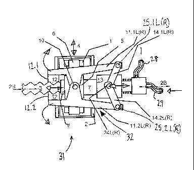
[0032] Gripper 32 has four gripper arms 11.1L,11.2L,11.1R,11.2R
which are mounted on central block 5 on pivots 10R,10L such that
gripper arms 11.1L,11.2L are mounted on pivot 10L and gripper arms
11.1R,11.2R are mounted on pivot 10R. At the distal end of gripper 32,
gripper arms 11.1L and 11.1R are connected by jaws 12.1 and gripper
arms 11.2L and 11.2R are connected by jaws 12.2 such that jaws
12.1,12.2 are arranged to engage the exterior of the proximal end of the
rock bolt 3. At the proximal end of gripper 32, the gripper arms
11.1L,11.2L,11.1R,11.2R of gripper 32 are connected to gripper drive 13
by toggle levers 14.1L,14.2L,14.1R,14.2R at pins
25.1L,25.2L,25.1R,25.2R respectively.
[0033] Gripper drive 13 forms an internal cylindrical channel for
slideably receiving supply pipe 8. Gripper drive 13 forms on its distal
end a stepped shaped drive chamber 16 which is shaped to receive guide
pipe 7 such that guide pipe 7 and drive chamber 16 form a second
hydraulic chamber 16/piston 7 pairing or second force transmitter.
Hydraulic fluid is supplied to the hydraulic drive chamber 16 by hydraulic
connection 17. Hydraulic drive chamber 16 has an annular shape as it is
formed by gripper drive 13, supply pipe 8 and guide pipe 7. The supply
of hydraulic fluid to first and second hydraulic chamber/piston pairings
are controlled by control means (not shown).
[0034] Gripper drive 13 has toggle lever joints 24L,24R. Toggle levers
14.1L,14.2L are attached to toggle lever joint 24L and toggle levers
14.1R,14.2R are attached to toggle lever joint 24R. The toggle levers
14.1L,14.2L,14.1R,14.2R are arranged such that when the apparatus is
arranged flush with rock bolt 3 and second hydraulic chamber 16/piston 7
CA 02747333 2011-06-16
WO 2010/070445
PCT/1B2009/007850
11
pairing is operated so that hydraulic drive chamber 16 is filled with
hydraulic fluid from hydraulic connection 17, gripper drive 13 moves
proximally by sliding on supply pipe 8 away from guide pipe 7, the toggle
levers 14.1L,14.2L,14.1R,14.2R are forced outwards to rotate the four
gripper arms 11.1L,11.2L,11.1R,11.2R about pivots 10R,10L such that
jaws 12.1,12.2 grip on the exterior of the proximal end of rock bolt 3.
[0035] Spring 23 is arranged on the exterior of supply pipe 8 and each
end of spring 23 is fixed to gripper drive 13 and to coupling piece 30
such that when gripper drive 13 is moved proximally, the spring 23 is
compressed such that when hydraulic fluid is drained from hydraulic
drive chamber 16 and from hydraulic block chamber 21, the spring 23
moves the gripper drive 13 distally and supply pipe 8 proximally such
that they are returned to their original positions.
[0036] Alternatively, the Figures of the accompanying drawings may be
described as follows. The apparatus for connecting supply pipes for
plastics components to an inner channel of a rock bolt (anchor rod) in a
pressure-tight manner, the opening to which rock bolt projects from a
drill hole, has two hydraulic force transmitters, clamping device and
pressing device 20, 21, functioning as cylinder piston units. The force
transmitters have a common component, the central block (5). This
central block (5) can be clamped onto the anchor rod 3 by the clamping
device and concentrically has a supply pipe which can be connected in a
pressure-tight manner to the anchor rod 3 joining.
[0037] The central block forms, on the one side of the clamping device,
the fixed piston for a cylinder, which is moveably guided on it, toggle
lever drive block (13), which serves as the clamping device.
[0038] This central block (5) forms, on the other side, the fixed cylinder
for the supply pipe (7) designed as a piston and serves as the pressing
device 20, 21.
CA 02747333 2011-06-16
WO 2010/070445
PCT/1B2009/007850
12
[0039] The force of the clamping device is increased by a toggle lever
connection.
[0040] In detail, the apparatus consists of the following elements:
[0041] A support frame 1 is guided so as to be translationally moveable
in a guide track 2 with a movement axis 4 aligned perpendicularly to the
anchor rod 3. The central block 5 can be pivoted in the support frame
about a pivot shaft 6 (alignment shaft) which is parallel to the movement
axis 4 of the support frame. The guide pipe 7 is a component part of the
central block, which is firmly connected to the central block 5.
[0042] A supply pipe 8 for supplying hardening plastics components to
the inner channel 9 of the anchor rod 3 is guided in the central block,
with the guide pipe 7 attached thereto, concentrically and so as to slide,
wherein the axis of the supply pipe essentially intersects the alignment
shaft 6 of the central block 5.
[0043] By translationally moving and positioning the support frame 1 in
the guide track 2 and by pivoting the central block 5 about the pivot shaft
6 (alignment shaft) which is parallel to the movement axis 4 of the
support frame, the guide pipe 8 can be positioned flush with the anchor
rod 3 and the joining of its inner channel.
[0044] Two pivot pins 10.L and 10.R are firmly attached to the central
block 5 on the right and left (at the top and the bottom) perpendicularly to
the alignment shaft 6 and the guide track 2. These pivot pins are used as
the gripper tongs shaft for gripper tongs 11. The gripper tongs have two
two-armed lever pairs 11.1 and 11.2 which can be pivoted in opposed
directions. Each two-armed lever pair consists of the two left two-armed
levers 11.1L and 11.2L and the two right two-armed levers 11.1R and
11.2R.
CA 02747333 2011-06-16
WO 2010/070445
PCT/1B2009/007850
13
[0045] The two-armed levers, which are parallel to each other, of each
two-armed lever pair are connected to one another at the end of the one
arm, the gripper arm, by a cross-piece. This cross-piece serves and is
designed as the gripper jaw 12 for clasping and gripping the end of the
anchor rod 3.
[0046] The two-armed levers, which are parallel to each other, of each
two-armed lever pair are connected at the free end of the other arm, the
power lever arm, to a pair of toggle joint levers.
[0047] A toggle lever drive block 13 is used to drive the gripper tongs.
This is guided so as to slide, concentrically to the outer circumference of
the central block and the guide pipe 7 attached thereto, on the outer
circumference of the guide pipe. It is used to drive the two identical
toggle lever pairings 14.1L and 14.2L as well as 14.1R and 14.2R, which
with their central joints 24L and 24R are coupled to pins on both sides
left and right of the toggle lever drive block and are coupled with their
free end, in each case, to the other end of the two-armed levers 11.
[0048] The hydraulic gripper drive 15 is formed by the toggle lever
drive block 13 inside (Fig. 2B) forming a cylinder chamber 16 with the
central block and guide pipe 7, wherein the central block is fixed and the
toggle lever drive block 13 opposite the central block can be moved in a
piston-like manner. The cylinder chamber is sealed opposite the guide
pipe 7 at the ends and has a hydraulic connection 17 (Fig. 2A). The
toggle lever drive block 13 is supported by a spring 23 opposite the guide
pipe for the purpose of slackening the toggle lever, so that the toggle
lever pairs buckle about the toggle lever joint 24L and 24R and the
gripper jaws 12 are moved for the purpose of slackening. The hydraulic
gripper drive 15 functions in such a way that the toggle lever drive block
13 is moved against the force of the spring 23, by the hydraulic pressure
built up in the cylinder chamber, for the purpose of extending the toggle
CA 02747333 2011-06-16
WO 2010/070445
PCT/1B2009/007850
14
lever pairs. By means of this extension, the gripper jaws 12 are moved
for the purpose of tension, so that the gripper jaws grip tightly the anchor
rod 3, provided with a thread on its circumference, and clamp onto the
central block via the pivot pins 1OR and 10L, and vice-versa. When this
has occurred by means of the gripper drive applying hydraulic pressure,
the supply pipe 8 can be pressed in a sealing manner against the opening
of the inner channel 9 of the anchor rod 3 with the static mixer arranged
therein. A hydraulic sealing drive 19 is used for this purpose. This is
formed by the supply pipe on its outer circumference being designed as a
stepped piston 20 which in the interior of the central block 5, designed
with a staged diameter, forms a cylinder chamber 21. This cylinder
chamber is delimited in a sealing manner on one side by the end of the
supply pipe 8 with the larger diameter and on the other side by the
reducing diameter stage of the interior of the central block 5. The
cylinder chamber 21 is connected to a hydraulic line 22.
[0049] In Fig. 2B, seals are provided with which, in particular, the
hydraulic cylinder chambers are sealed. Providing such seals falls within
the competence of a person skilled in the art of hydraulics and therefore
will not be described further here.
[0050] If the supply pipe 8 is now pressed against the opening of the
inner channel 9 of the anchor rod 3, the plastics components can be
delivered. For this, two pipes are placed in the inner channel of the
supply pipe 8, specifically an inner pipe 26 and an outer pipe 27,
concentric in relation to one another. In order to connect these pipes to
the plastics feed pipes 28, 29, a fluid coupling 30 is screwed onto the
central block, specifically on to the end of the guide pipe projecting from
the toggle lever drive block 13. The hoses of the plastics feed pipes 28,
29 are attached to this fluid coupling 30 on the outside. On the inside,
they have the separate channels for the inner pipe and the outer pipe. The
fluid coupling can also be used to support the spring 23.
CA 02747333 2011-06-16
WO 2010/070445
PCT/1B2009/007850
[0051] It is important for the plastics components to remain separate
until they reach the joining to the inner channel 9 of the anchor rod 3 and
for them to be mixed only in the anchor rod in the static mixer arranged
therein. Thereby, the reaction time for hardening of the plastics
components begins at the same point in time as the filling time for filling
the drill hole including the inner channel of the anchor rod. The required
filling time and the reaction time can, therefore, be exactly matched with
one another by adjusting the delivery ratios of the plastics components.
CA 02747333 2011-06-16
WO 2010/070445
PCT/1B2009/007850
= 16
Reference symbols:
1. Support frame 1;
2. Guide track 2;
3. Anchor rod 3; also referred to herein as rock bolt 3;
4. Movement axis 4;
5. Central block 5;
6. Pivot shaft 6 (alignment shaft);
7. Guide pipe 7;
8. Supply pipe 8;
9. Inner channel 9 of the anchor rod 3;
Two pivot pins 10 which are each referred to as 10L and 10R; also
referred to as gripper tongs shaft 10;
11. Two-armed lever 11; also referred to as gripper arms
11.1L,11.2L,11.1R,11.2R;
12. Gripping jaws 12; also referred to as jaws 12.1,12.2;
13. Toggle lever drive block 13; also referred to herein as gripper drive
13;
14. Two identical toggle lever pairings 14; also referred to herein as
toggle levers 14.1L,14.2L,14.1R,14.2R;
15. Hydraulic gripper drive 15;
16. Cylinder chamber 16; also referred to herein as stepped shaped drive
chamber 16;
17. Hydraulic connections 17;
18. Annular piston 18;
19. Sealing drive 19;
20. Stepped piston 20, pressing device;
21. Cylinder chamber 21; also referred to herein as stepped shaped block
chamber 21;
22. Hydraulic line 22;
23. Spring 23;
CA 02747333 2011-06-16
WO 2010/070445
PCT/1B2009/007850
17
24. Toggle lever joint 24; also referred to herein as toggle lever joints
24L,24R;
25. Pin 25; also referred to herein as pins 25.1L,25.2L,25.1R,25.2R;
26. Inner pipe 26;
27. Outer pipe 27;
28. Plastics feed pipe 28;
29. Plastics feed pipe 29;
30. Fluid coupling 30; also referred to herein as coupling piece 30;
31. Apparatus 31;
32. Gripper 32;
33. Radial connection 33; and
34. Coaxial connection 34.