Note: Descriptions are shown in the official language in which they were submitted.
CA 02747445 2011-07-26
METHOD OF DESIGNING A DRIVER'S COMPARTMENT
FIELD
The subject matter of the present application relates to a method of designing
a
driver's compartment for accommodating a predetermined range of driver's sizes
comprising a smallest size and a largest size, and a movable driver's seat for
the driver's
compartment.
BACKGROUND
Economic and regulatory considerations cause designers to design driver's
compartments of vehicles to accommodate drivers of a range of different sizes.
This
includes sizing a multitude of features of a vehicle's driver's compartment to
suit both an
upper end and lower end of the range.
An appreciation of the complexity of the features involved in merely
positioning
a driver in a driver's compartment can be received by review of known
conventional
driver's compartment designs shown in Figs. 1 and 2. This design takes into
consideration vertical and or horizontal distances of different body parts of
the driver to
determine various elements in the driver's compartment, for example, the
distance
between the head and the front window, the distance between the knees and the
floor,
etc.
Consequent to the need to suit a driver's compartment to drivers of different
sizes, the size of a driver's compartment can be significantly larger than
would be the
case for a driver's compartment which is designed for only a driver of a
single size.
SUMMARY
Throughout the present application, reference will be made to a driver's seat.
For the purposes of the specification and the claims, the term "driver's seat"
includes the following features, described with reference to a seat generally
designated
as 10 in Figs. 3A and 3B: a base portion 12 and a back portion 14; the base
portion
comprising an upper surface 16, the upper surface 16 having opposing front and
rear
edges (18,20) and side edges (22,24) extending therebetween; a Seat Reference
Point
CA 02747445 2011-07-26
-2-
(SRP) on the upper surface 16 of the base portion 12 being disposed equally
spaced
from the side edges (22,24) thereof and at an area of intersection of the back
portion 14
and the upper surface 16.
As will be understood, an SRP in the present application refers to a position
of a
part of a seat in a driver's compartment, and corresponds in meaning to that
shown in
Fig. 44 of MIL-STD-1472F, upon which Figs. 3A and 3B are based.
Additionally, reference in the present application will be made to a Seat Pan
Height Reference Point (SPHRP), which is a term that does not appear in MIL-
STD-
1472F, but is defined, with reference to Figs. 3A and 3B, as a point disposed
on the
front edge 18 of the upper surface 16 of the base portion 12, the SPHRP being
equally
spaced from the side edges (22,24).
In accordance with a first aspect of the subject matter of the present
application,
there is provided a method of designing a driver's compartment for
accommodating a
predetermined range of driver's sizes comprising a smallest size and a largest
size, the
compartment having a floor and a top end, the method including:
a. designing a driver's seat having a seat reference point (SRP) used to
define
a position of a corresponding part of the seat in the compartment and a seat
pan height reference point (SPHRP) used to define a position of the front
portion of the seat in the compartment;
b. providing a seat moving mechanism configured to move at least said SRP
vertically in the compartment between a first position in which the SRP is
disposed at a first vertical distance H1 from the top end and the SPHRP is
disposed at a vertical distance of at least H3 from the floor, and in which
the
seat is configured to accommodate a driver of the smallest size, and a second
position in which the SRP is disposed at a second vertical distance H2 from
the top end, and the SPHRP is disposed at a vertical distance of at least H3
from the floor, H2 being greater than H 1 and in which the seat is configured
to
accommodate a driver of the largest size;
c. disposing the top end at a vertical distance H4 from the floor, the
distance
H4 corresponding to the sum of HI and H3, so that the vertical distance H4 of
the top end suits for accommodating the driver of the largest size is the seat
only in said second portion.
CA 02747445 2011-07-26
3-
The method above can enable a driver's compartment to be smaller than would be
the case in the comparative examples shown in Figs. 1 and 2, where the driver
of the
largest size is seen to sit at a height greater than a driver of a smaller
size. An advantage
of the method can be that a design of the driver's compartment can suit a
range of sizes
of drivers, by designing a seating position of a larger driver to be lower
position than a
smaller driver, which is larger than a range of sizes enabled with
conventional seating
positions, i.e. with the larger driver being seated higher up.
The method can further include limiting a vertical dimension of at least front
window area of the compartment to suit the vision cone of the largest size
driver in the
second position.It will be appreciated that in some vehicles the material
thereof having
the highest areal density is the transparent material constituted by the
vehicle's glass
and/or transparent armor (for military vehicles). An advantage of reducing the
window
area of a driver's compartment can improve the mobility of the vehicle.
According to
one design, such method can allow a 100mm change in height between the SRP of
the
largest and smallest driver to achieve a reduction of approximately 14% per
meter
squared of transparent material in a driver's compartment.
The method can further include designing the driver's seat to be movable by
said
seat moving mechanism into a number of additional positions between the first
and
second positions, the vertical distance of the SRP from the top end in said
additional
positions gradually increasing in the direction towards the second position.
a. designing the seat moving mechanism to maintain a vertical distance of the
SPHRP from the floor at a constant height or a height gradually decreasing in
the direction towards the second position; and
b. designing the seat moving mechanism into a number of additional positions
between the first and second positions, the vertical distance of the SRP from
the top end in said additional positions gradually increasing in the direction
towards the second position; a rate of increase of the vertical distance of
the
SRP from the top end in said additional positions in the direction towards the
second position being greater than a rate of decrease of the vertical distance
of
the SPHRP from the floor in said additional positions in the direction towards
the second position.
CA 02747445 2011-07-26
-4-
The method can further include configuring a front edge of a base portion to
move
only along a horizontal plane. The method can further include configuring an
SPHRP to
move only along a horizontal plane.
An advantage of reducing the vertical dimension of the roof of a driver's
compartment can improve the mobility of the vehicle.
Another advantage can be that such reduction can allow a more compact driver's
compartment design than would otherwise be achievable in a military vehicle
produced
in accordance with the recommended clearances of Table XX of MIL-STD-1472F,
shown below.
TABLE XX. Recommended clearances around equipment operator's station to
accommodate the 95th percentile soldier dressed in Arctic clothing.
Operator seat in rear most position (Figure 45)
A. Elbow (dynamic) 91 cm (36 in)
B. Elbow (static) 71 cm (28 in)
C. Shoulder 58 cm (23 in)
D. Knee width (minimum) 46 cm. (18 in)
E. Knee width (optimum) 61 cm (24 in)
F. Boot (provide adequate clearance to operate brake pedal without 1.5 can (6
in)
inadvertent acceleration operation)
G. Pedals (minimum) S cm (2 in)
H. Boot (provide adequate clearance to operate accelerator without 15 cm (6
in)
interference b_y brake pedal)
1. Head (seat reference point (SELF') to roof line) 107 cm (42 in)
2. Abdominal (seat back to steering wheel) 41 cm (16 in)
3. Front of knee (seat back to manual controls on dash) 74 cm (29 in)
4. Seat depth (seat reference point to front edge of seat pan) 41 can (16 in)
5. Thigh (under side ofsleering wheel to seat pan) 24 can (9.5 in)
6. Seat pan height 38 cm (15 in)
7. Boot (front of seat pan to heel point of accelerator) 36 cm (14 in)
8. Minimum mitten clearance around steering wheel 8 cm (3 in)
9. Knee--leg thigh (brakUclutch pedals to louver edge of steering wheel) 66
can (26 in)
The method can include designing the driver's compartment to comply with any
combination of the recommended clearances in the table above.
The top end, such as the compartment's ceiling can be limited in accordance
with
a specific ratio of the SRP. According to one example the method can include
limiting a
ratio of a vertical distance from the SRP to the floor and H2 in said second
position, to
CA 02747445 2011-07-26
S-
not exceed 330:1070. In such case the method can also include limiting a
vertical
dimension of the top end to suit the vertical distance of the SRP from the
floor and a
vertical distance from the SRP to the top end H1, in said first position of
the smallest
size driver, to not exceed 347:1053.According to another example, the method
can
further include limiting a ratio of a vertical distance from the SRP to the
floor and H2 in
said second position, to not exceed 290:1070. In such case the method can also
include
limiting a vertical dimension of the top end to suit the vertical distance of
the SRP from
the floor and a vertical distance from the SRP to the top end H1, in said
first position of
the smallest size driver, to not exceed 347:1053. According to yet a further
example, the
method can including limiting a ratio of a vertical distance from the SRP to
the floor
and H2 in said second position, to between 280:1070 and 290:1070. According to
another example, the method can include limiting a ratio of a vertical
distance from the
SRP to the floor and H2 in said second position, to not exceed 280:1020. In
such case
the method can also include limiting a vertical dimension of the top end to
suit the
vertical distance of the SRP from the floor and a vertical distance from the
SRP to the
top end HI, in said first position of the smallest size driver, to not exceed
347:953.
The method can further include limiting a ratio of the horizontal motion to
vertical
motion of the SRP to 2.8:1.
The method can further include designing the driver's compartment to be
protected by armor.
In accordance with another aspect of the subject matter of the present
application,
there is provided a vehicle comprising a driver's compartment having a front
window
area, a driver's seat and a seat moving mechanism; the driver's seat having a
seat
reference point (SRP) used to define a position of a corresponding part of the
seat in the
compartment; the seat moving mechanism being configured to move the driver's
seat
into a number of positions, each different position including the SRP at a
different
horizontal distance from the front window area and a different vertical
distance from the
floor, each position having a horizontal distance the front window area which
is greater
than a different position having a vertical distance of the SRP from the floor
smaller
then said different position.
Such seat moving mechanism can have the advantage of overcoming a natural
tendency of a driver to elevate the driver's seat to a maximum height in order
to gain
better vision.
CA 02747445 2011-07-26
-6-
The vehicle can further comprise a seat pan height reference point (SPHRP)
used
to define a position of a corresponding part of the seat in the compartment,
the seat
moving mechanism being configured to maintain a vertical distance of the SPHRP
from
the floor at a constant height.
The seat moving mechanism can be configured to move the SRP at a ratio of
horizontal distance to vertical distance of 1:2.8.
The vehicle, driver's compartment, and driver's seat of the present aspect can
have
any combination of features described above in connection with the first
aspect.
The vehicle can be an armored vehicle.
In accordance with either of the aspects above, the driver's compartment can
be
designed to be compliant with MIL-STD-1472F. Accordingly:
- a vertical distance from the SRP to the roof in said second position, i.e. a
position designed for a largest driver size in the range, can be 1400mm or
less
(item no. 1 of Table XX, the recommended clearance for the head);
- the largest size in the predetermined range of driver's sizes can be a 95th
percentile soldier, compliant with section 5.12.1 and Table XX of MIL-STD-
1472F.
- the smallest size in the predetermined range of driver's sizes can be a 5th
percentile soldier compliant with section 5.12.1 of MIL-STD-1472F.
It will be understood that the specific examples given with respect to MIL-STD-
1472F are for understanding of the subject matter of the present invention.
Therefore,
should this standard be replaced in future with a subsequent updated standard
having
modified recommended clearances, the SRP, vertical distance from the SRP to
the
ceiling in said second position, largest size and smallest sizes in the
predetermined
range of driver's sizes can be designed in accordance with the updated
standard, without
departing from the subject matter of the present application.
BRIEF DESCRIPTION OF THE DRAWINGS
In order to understand the subject matter of the present application and to
see
how it can be carried out in practice, embodiments will now be described, by
way of
non-limiting example only, with reference to the accompanying drawings, in
which:
Fig. 1 is a schematic side view of a design of a known truck driver's
compartment;
CA 02747445 2011-07-26
-7-
Fig. 2 is a schematic side view of a design of a known car driver's
compartment;
Fig. 3A is a schematic top view of a seat from Fig. 44 of MIL-STD 1472F with
additional reference numerals added thereto;
Fig. 3B is a schematic sectional side view of the seat in Fig. 3A, also from
Fig.
44 of MIL-STD 1472F with additional reference numerals added thereto;
Fig. 4 is a schematic side view of a driver's compartment designed to
accommodate drivers of two different sizes;
Fig. 5A is a schematic side view of a driver's compartment designed in
accordance with the subject matter of the present application;
Fig. 5B is a schematic side view of the driver's compartment in Fig. 5A, with
a
modified driver's position;
Fig. 6 is a schematic representation of a side view of an SRP, SPHRP, and
imaginary line connecting same, of a driver's seat in accordance with the
subject matter
of the present application, in different positions, the positions being spaced
from each
other for ease of explanation;
Fig. 7 is a schematic representation of some of the positions of the SRP,
SPHRP,
and imaginary line in Fig. 6; and
Fig. 8 is a schematic side view of an example driver's seat.
DETAILED DESCRIPTION
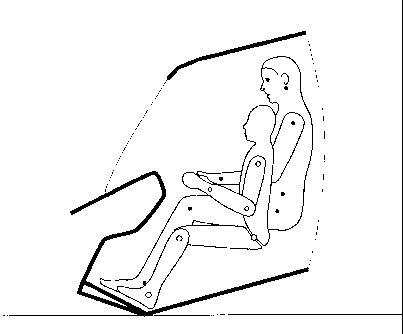
Referring now to the drawings wherein like reference characters designate like
or corresponding parts throughout several views, there is shown in Fig. 4 a
driver's
compartment generally designated as 30.
The driver's compartment 30 comprises a top end, such as a ceiling 31 and a
compartment floor 36. The compartment 30 is designed to accommodate a larger
driver
32 and a smaller driver 34 while being seated on a vehicle seat, generally
designated 29.
It will be understood that in reality each driver is seated on a driver's seat
29 as defined
above, however for the purposes of explanation, in the present view, the seat
is shown
in two different positions, a large driver position and a small driver
position, with
schematic lines 35, and 37representing a back portion of a seat in the large
driver
position, and in the small driver position, respectively. Similarly, SRP,
SPHRP and
imaginary lines 39 and 41 joining same are shown for both positions. The SRP
for both
positions is at approximately the same vertical distance (Hl) from the ceiling
31 of the
CA 02747445 2011-07-26
-8-
driver's compartment 30. In order to accommodate the two drivers, the SPHRP of
the
large driver position and the SPHRP of the small driver position are at
different
horizontal distances Ll and L2 from a front window area 38 of the driver's
compartment 30. The different horizontal distances L1 and L2, are
approximately
200mm apart.
As a result of the different sizes of the small and large driver, the height
of the
compartment H4, must be designed to accommodate the seat with the larger
driver 32
seated thereon, which is the sum of the height of the SPR and vertical
distance H1 from
the ceiling. Thus, in order to accommodate large drivers a larger compartment
is
required, which in a case of an armored vehicle requires additional surface
area to be
protected.
In addition, as a result of their different sizes, each of the two drivers 32
and 34
have a vision cone (40,42) which only partially overlaps the others vision
cone. Areas
of the vision cones which do not overlap are designated as 44 and 46. As can
be seen,
the front window area of the driver's compartment is designed to have a
vertical height
HWI suited to accommodate both vision cones. Thus, the front window area is
substantially large, which in the case of an armored vehicle requires
additional window
surface to be protected.
Referring now to Fig. 5A, there is shown a driver's compartment 50 having a
top
end, such as a ceiling 51, and a compartment floor 56. The compartment 50 is
designed
to accommodate a larger driver 32 and a smaller driver 34, while being seated
on seat
55. It can be seen that in the first position the driver's compartment 50, can
accommodate a small driver 34 while being seated on seat 55, with the SPR1
being at a
vertical distance HI from the ceiling 51.
In the second position, the driver's compartment 50, can accommodate a large
driver 34 by moving seat 55 to the second position in which SRP2 of the seat
55 is
lowered thereby increasing the vertical distance H2 between the SRP2 and the
ceiling
51.
It is appreciated that the seat 55 can alternate between the first and the
second
position while maintaining the same horizontal distances (LI, L2), from a
front window
area 39.
As a result of this design, the height of the compartment H4, can be smaller
than
the height of the compartment 30 of Fig. 4. This is due to the fact that SPR2
in the large
CA 02747445 2011-07-26
-9-
driver position is lower than the SPR1 in the small driver position, thus
compensating
for the difference between the vertical distance H2 required in the large
driver position
and the vertical distance Hl required in the small driver position. This
allows
minimizing the overall size of the compartment, thereby reducing the amount of
surface
area to be protected.
In addition, as can be seen in Fig. 5A, the vision cone 40 of the larger
driver 32
in this design encompasses a vision cone (not seen) of the smaller driver 34.
Thus, the
front window area of the driver's compartment is designed to have a vertical
height
HW2, which is suited to accommodate both vision cones. The magnitude of HW2 is
smaller than the magnitude of HWl of Fig. 4. This design allows for a smaller
surface
area to be protected, and for providing a smaller protected window surface.
Turning
now to Fig. 5B, it can be seen that the SPHRP of both positions can be
maintained at a
common vertical height from the floor 56, and the seat can be adjusted merely
by
reducing the height of the SRP of the larger driver, while maintaining the
same
horizontal distances (LI, L2), from a front window area 39. Thus, a gradient
of the
imaginary line 59 between the SPHRP2 and the SRP2 of the seat position
accommodating the larger driver 32 will have a larger magnitude than the
imaginary
line 61 between the SPHRP1 and the SRP1 of the seat position accommodating the
smaller driver 34. It is appreciated that maintaining the SPHRP in a fix
vertical position
for example at height H3from the floor 56, allows for further minimizing the
size of the
compartment 50. This is due to the fact that SPHRP according to some standard
must be
at a minimal height form the floor, for example, 380 mm, either for a small
driver or for
a large driver. Thus, providing a seat moving mechanism which is configured to
move
SRP in the compartment between the two vertical distances from the ceiling,
while
maintaining the SPHRP in a vertical distance of at least H3 from the floor,
allows for a
small driver and a large driver to be accommodated in the compartment 50,
while still
meeting the requirement of the vehicle seat standard. However, according to
another
example, the seat moving mechanism can be configured to allow vertical
movement of
the SPHRP so long as a minimum vertical height of H3 is maintained.
According to a further example, the seat in the compartment can be provided
with a seat moving mechanism for vertically moving the SRP and SPHRP, as
described
hereinabove, while also allowing horizontally moving the seat. For ease of
CA 02747445 2011-07-26
10-
understanding of the vertical and horizontal movement of the SRP and SPHRP
along a
desired path, attention is directed to Fig. 6.
In Fig. 6 a first position, generally designated as 60A closest to a front
window
area of a driver's compartment (not shown) showing an SPHRP, designated as
61A, an
SRP, designated as 62A, and an imaginary line joining same, designated as 63A.
A second position is shown generally designated as 60B, with the elements
thereof having numerals corresponding to the numerals of the first position
with the
addition of the designation character "B".
Similarly third, fourth, fifth, sixth and seventh positions are shown. The
final
position is designated by the character G, which is the position of greatest
horizontal
distance from the front window area 39.
Using X and Y coordinates, positions in millimeters, and assuming the
following
conditions: the SPHRP 61A of the first position 60A starts at position
(0,380), each
position is moved 33mm in a horizontal direction away from the front window
area, the
internal height of the compartment is 1350mm, and the length of the seat depth
is
410mm (item no. 4 in Table I above). Although the vertical positions of SPR
and the
SPHRP hereinabove were referred to with respect to the vertical distance from
the
ceiling, for the sake of clarity, the X coordinates here, are calculated as
the vertical
distance of SPR and the SPHRP with respect to the floor of the compartment. An
example set of coordinates of the SPHRP and SRP for each position shown can be
as
follows:
Position
designation
position suffix SPHRP SRP
x x
1 A 0 380 408.44 344.27
2 B 33 380 407.36 333.59
3 C 66 380 406.01 322.94
4 D 99 380 404.38 312.33
E 132 380 402.47 301.77
6 F 165 380 400.28 291.26
7 G 198 380 397.82 280.81
CA 02747445 2011-07-26
It will be understood that the horizontal spacing between the positions in
Fig. 6
is exaggerated in the drawing to allow understanding of the pivoting motion.
A more accurate rendering of the horizontal spacing can be seen in Fig. 7
where
the first, second and third positions (60A, 60B, 60C) are shown to demonstrate
horizontal motion of the SRP and SPHRP.
Shown in Fig. 8 is a driver's compartment, generally designated as 70, of an
armored vehicle (not shown). The driver's compartment 70 comprises a floor 71,
a roof,
73, a front window area 72 comprising a window 79 made of transparent armor, a
driver's seat 74 and a seat moving mechanism generally designated as 76.
The driver's seat comprising a back portion 78, base portion 80, and having a
seat reference point (SRP) used to define a position of a corresponding part
of the seat
in the compartment, and a seat pan height reference point (SPHRP).
The seat moving mechanism 76 comprising rails 78, front legs 80 configured to
slide along the rails 78 and pivotally attached to a front point 82 of the
base portion 80,
compressible springs 84 configured to slide along the rails 78, and a lever
mechanism
86 pivotally attached at point 88 to the floor 71. The lever mechanism 86
further
comprising a locking mechanism (not shown) for locking the lever mechanism 86
in a
desired position, or releasing it from that position.
In operation, when the locking mechanism 86 is not in a locked state, a user
can
slide the seat 74 in a horizontal direction, designated by arrow 90, away from
the front
window area 72, along the rails 78. During this motion, the lever mechanism 86
pivots
at the floor 71, causing the seat 74 to pivot in the direction of arrow 92,
about front
point 82, compressing springs 84 toward the floor 71, and moving the SRP away
from
the ceiling 73. The user can then lock the seat 74 at the desired orientation,
with the
SRP of the seat consequently being at a vertical distance from the ceiling 73
larger than
is the case when the seat is closer to the front window area 72. In this
position,
compartment 70 can accommodate a larger driver. As will be understood, the
seat 74
can be moved in a direction opposite to arrow 90, in which case the seat will
translate
horizontally towards the front window area and pivot about front point 82 in a
direction
opposite to an-ow 92, thereby moving the SPR toward the ceiling and allowing a
small
driver to be seated on seat 74, while maintaining the required vision cone. In
any event,
in both positions the SPHRP is not displaced toward the floor 71, below a
predetermined vertical distance, for example 380mm.
CA 02747445 2011-07-26
12-
Those skilled in the art to which this invention pertains will readily
appreciate
that numerous changes, variations, and modification can be made without
departing
from the scope of the invention, mutatis mutandis.