Note: Descriptions are shown in the official language in which they were submitted.
CA 02748138 2011-05-11
WO 2010/055344 PCT/GB2009/051526
Method and Apparatus for Droplet Deposition
The present invention relates to a method and apparatus for droplet
deposition and may find particular use within apparatus including fluid
chambers
separated by actuable piezoelectric walls.
In a particular example, the present invention relates to ink jet printers.
It is known within the art of droplet deposition apparatus to construct an
actuator comprising an array of fluid chambers separated by a plurality of
piezoelectric walls. In many such constructions, the walls are actuable in
response to electrical signals to move towards one of the two chambers that
each wall bounds; such movement affects the fluid pressure in both of the
chambers bounded by that wall, causing a pressure increase in one and a
pressure decrease in the other.
Nozzles or apertures are provided in fluid communication with the
chamber in order that a volume of fluid may be ejected therefrom. The fluid at
the aperture will tend to form a meniscus owing to surface tension effects,
but
with a sufficient perturbation of the fluid this surface tension is overcome
allowing
a droplet or volume of fluid to be released from the chamber through the
aperture; the application of excess positive pressure in the vicinity of the
aperture
thus causes the release of a body of fluid.
An exemplary construction having an array of elongate chambers
separated by actuable walls is shown in Figure 1. The chambers are formed as
channels enclosed on one side by a cover member that contacts the actuable
walls; a nozzle for fluid ejection is provided in this cover member. The cover
member will often comprise a metal cover plate, which provides structural
support, and a thinner overlying nozzle plate, in which the nozzles are
formed.
As shown in Figure 1, the actuation of the walls of a chamber may cause
the release of fluid from that chamber through its aperture. In the case shown
in
Figure 1, both the walls of a particular chamber are deformed inwards, this
movement causing an increase in the fluid pressure within the channel and a
decrease in pressure of the two neighbouring channels. The increase in
CA 02748138 2011-05-11
WO 2010/055344 PCT/GB2009/051526
-2-
pressure within that chamber contributes to the release of a droplet of fluid
through the aperture of that chamber.
In constructions such as Figure 1 where all chambers are provided with an
aperture, every chamber may be capable of fluid release. It will be apparent
however, that since the actuation of a particular wall has a different effect
on the
pressure in its two adjacent channels, simultaneous release of fluid from both
of
the channels separated by a particular wall is difficult to achieve.
There may be some asymmetry in the design of the apparatus to enable
droplets released at different times to arrive on a substrate at the same
time; for
example, the nozzles may be located in different positions for different
channels.
During deposition the array will be moved perpendicular to the array
direction,
thus two nozzles may be spaced in the direction of movement so that the
spacing
in position counteracts the difference in timing of droplet release. However,
such
constructional changes are permanent for an actuator and are thus able to
compensate for only a specific pattern of droplet release timings; this leads
to
restriction of the methods used to drive the actuator walls.
A further complication caused by the actuation of a wall shared by two
chambers is that residual pressure disturbances remain in the chamber after
the
actuation has occurred. Experiments carried out by the Applicant have led to
the
data shown in Figure 2 for the displacement within a fluid (acting as a proxy
for
the pressure within the fluid) in two neighbouring chambers following a single
movement of the dividing wall. It is apparent from these data that the
pressure in
each chamber oscillates about the equilibrium pressure (the pressure present
in
a chamber where no deformation of the walls takes place), with the amplitude
of
oscillation decaying to zero over time. The time taken for the amplitude to
decay
to zero is referred to hereinafter as the relaxation time (tR) for the system.
Without wishing to be bound by the theory the Applicant believes that the
oscillation of pressure is caused by pressure standing waves set up by
acoustic
waves reflected within the fluid chamber. The period (TA) of these standing
waves may be derived from a graph such as Figure 2 and is known as the
CA 02748138 2011-05-11
WO 2010/055344 PCT/GB2009/051526
-3-
acoustic period for the chamber. In the case of a long, thin channel this
period is
approximately equal to I/c where I is the length of the channel and c is the
speed
of sound within the chamber.
As mentioned above, residual pressure waves are present in both
chambers either side of a wall following the movement of that wall. The
presence
of such residual waves is apparent from the second and subsequent maxima in
displacement shown in Figure 2. Therefore, when fluid is released from a
particular chamber, pressure disturbances may be present in one or both of the
neighbouring chambers. For example, in some actuation schemes fluid is
released from a particular chamber by the inward movement of both walls
bounding that chamber, which will affect the pressure in both the neighbouring
chambers. These pressure disturbances may interfere with fluid release from
the
neighbouring chambers in a process known as `cross-talk'.
Actuator constructions have been proposed to ameliorate the problem of
`cross-talk'; for example, alternate chambers may be formed without apertures
so
that these `non-firing' chambers act to shield the chambers with apertures -
the
`firing' chambers - from pressure disturbances. It will of course be apparent
that
for a given chamber size this has the undesirable consequence of halving the
resolution available.
EP 0 422 870 proposes to ameliorate cross-talk with actuation schemes
that pre-assign each chamber to one of three or more groups or `cycles'. The
chambers in turn are cyclically assigned to one of these groups so that each
group is a regularly spaced sub-array of chambers. During operation, only one
group is active at any time so that chambers depositing fluid are always
spaced
by at least two chambers, with the spacing dependent on the number of groups.
User input data determines which specific chambers within each group are
actuated. In more detail, the chambers within a cycle chamber may each receive
a different number of pulses corresponding to the number of droplets that are
to
be released by that chamber, the droplets from each chamber merging to form a
single mark or print pixel on the substrate.
CA 02748138 2011-05-11
WO 2010/055344 PCT/GB2009/051526
-4-
It will be apparent that at any one time only one third of the total number of
chambers (or 1/n, where n is the number of cycles) may be actuated in this
scheme and that therefore the rate of throughput is substantially decreased.
Additionally, the time delay between the firing of different groups can lead
to the corresponding dots on the substrate being spaced apart in the direction
of
relative movement of the substrate and the apparatus. As noted briefly above,
some apparatus constructions address this problem by offsetting the nozzles
for
each cycle, so that the nozzles for each cycle lie on a respective line, the
lines
being spaced in the direction of substrate movement, while this often
successfully
counteracts this particular problem, this construction is generally restricted
to a
particular firing scheme following nozzle formation.
EP 0 422 870 also proposes an actuator where the chambers are divided
into two groups - odd-numbered and even-numbered chambers. Each group of
chambers is synchronised to fire at the same time, with the specific input
data
determining which chambers within that group should be fired. The disclosure
also discusses switching between the two groups at the resonant frequency of
the chambers so that neighbouring chambers are fired in anti-phase.
It is noted in the document that this scheme grants a high throughput rate,
but results in restrictions to the patterns that may be produced. For example,
according to this scheme it is possible to print white-black-white, but not
black-
white-black.
Thus, there exists a need for a droplet deposition apparatus that has an
increased throughput rate with less restriction in the patterns that may be
produced.
The Applicant has recognised that in the case of the odd-even channel
system proposed in EP 0 422 870, the division of the chambers into two groups
allows the residual pressure fluctuations in neighbouring chambers to be used
beneficially in promoting the ejection of fluid. The applicant has further
recognised that the same fundamental benefits in terms of increased throughput
may still be afforded when only an isolated pair of neighbouring chambers is
CA 02748138 2011-05-11
WO 2010/055344 PCT/GB2009/051526
-5-
operated at or close to the resonant frequency of the chambers. Therefore, a
system can be devised where the actuation of an array of chambers comprises
the actuation of a plurality of such pairs of neighbouring chambers.
The Applicant has also recognised that the symmetry of the odd-even
channel scheme of EP 0 422 870 includes the symmetric deformation of both the
walls of a particular channel in order to eject a droplet and that this
symmetry
leads in part to the restriction in the patterns that may be printed.
Thus, according to a first aspect of the present invention there is provided
a method for depositing droplets onto a substrate, utilising an apparatus
comprising:
an array of fluid chambers separated by interspersed walls, each fluid chamber
being provided with an aperture and each of said walls separating two
neighbouring chambers; wherein each of said walls is actuable such that, in
response to a first voltage, it will deform so as to decrease the volume of
one
chamber and increase the volume of the other chamber, in response to a second
voltage, it will deform so as to cause the opposite effect on the volumes of
said
neighbouring chambers; wherein each of said walls is actuable such that, in
response to a first voltage, it will deform towards one of its two
neighbouring
chambers, thus decreasing the volume of that chamber and increasing the
volume of the other chamber, in response to a second voltage, it will deform
towards the other of its two neighbouring chambers, causing the opposite
effect
on the volumes of the neighbouring chambers;
the method comprising the steps of:
receiving input data;
selecting pairs of adjacent fluid chambers based on said input data, assigning
said selected pairs of adjacent fluid chambers as firing chambers and the
remaining fluid chambers as non-firing chambers, wherein one of said pairs of
firingchambers is spaced apart from another of said pairs of firing chambers
by
an odd number of non-firing chambers;
CA 02748138 2011-05-11
WO 2010/055344 PCT/GB2009/051526
-6-
for each of said selected pairs, actuating the separating wall of said pair of
firing
chambers so as to cause the deposition of at least one droplet from each of
said
firing chambers;
wherein said actuations of said selected pairs overlap in time.
Depositing drops by actuating the dividing wall of a pair of neighbouring
chambers advantageously allows pairs to be spaced by one chamber only and
thus it is possible to print black-white-black, so increasing the patterns
that may
be produced. More, selected pairs may be spaced by any number of chambers
so that there is no longer an assignment of odd and even chambers, this
difference being particularly apparent as the pairs may be spaced apart by an
odd number of chambers.
Further, by taking account of the input data in determining which pairs
should be selected, the procedure may be optimised so as to minimise the
effect
of any remaining restrictions on patterns.
In contrast to known apparatus discussed above, apparatus adapted to
carry out a method according to the present invention may advantageously have
the apertures for substantially all fluid chambers are disposed on a line,
thus
greatly simplifying integration of the print head or other droplet deposition
apparatus within a printer or other larger system and also allowing a variety
of
actuation schemes falling within the scope of the present invention to be
used.
The invention will now be described with reference to the accompanying
drawings, in which:
Figure 1 shows a known construction of a droplet deposition apparatus;
Figure 2 shows the pressure response in two neighbouring chambers to
the deformation of the wall separating the chambers;
Figure 3(a) shows the droplet deposition apparatus of Figure 1 undergoing
a different series of actuations, while Figure 3(b) is a simplified
representation of
the same series of actuations;
CA 02748138 2011-05-11
WO 2010/055344 PCT/GB2009/051526
-7-
Figure 4(a) shows an end-view and Figure 4(b) a side-view of a still further
exemplary construction of a droplet deposition apparatus where each chamber
opens onto a manifold at opposing ends;
Figure 5(a) shows an end-view and 5(b) a side-view of yet a further
exemplary construction of a droplet deposition apparatus where each chamber
opens onto a manifold at only one end;
Figure 6(a) shows an end-view and 6(b) a side-view of a still further
exemplary construction of a droplet deposition apparatus where a small passage
connects each chamber to a manifold;
Figure 7 illustrates a method of converting input data into actuations in
accordance with a first embodiment of the present invention;
Figures 8(a) and 8(b) are representations of a method of operating a
droplet deposition apparatus in accordance with the embodiment of Figure 7;
Figures 9(a) and 9(b) are representations of a method of operating a
droplet deposition apparatus in accordance with a further embodiment of the
present invention using the same input data as figures 7 and 8, but where all
walls are continuously active;
Figure 10 illustrates a method of converting input data into actuations in
accordance with a further embodiment of the present invention, where a single
droplet may be released from a selected pair of chambers;
Figures 11(a) and 11(b) are representations of a method of operating a
droplet deposition apparatus in accordance with the embodiment of Figure 10;
Figures 12 and 13 illustrate respectively the effect on text and images of a
method of converting input data in accordance with the present invention;
Figure 14 shows a voltage waveform that may be applied to a pair of
chambers being actuated according to the method of Figure 8;
CA 02748138 2011-05-11
WO 2010/055344 PCT/GB2009/051526
-8-
Figure 15 shows a voltage waveform according to a still further
embodiment of the present invention comprising a series of alternating
positive
and negative portions;
Figure 16 shows a voltage waveform according to yet a further
embodiment of the present invention where a non-ejection waveform portion
precedes a series of positive and negative waveform portions.
The apparatus shown in Figure 1 may be used to carry out a method of
droplet deposition in accordance with the present invention. The apparatus of
Figure 1 comprises an array, extending in an array direction, of fluid
chambers
formed as channels or elongate chambers, each having a longitudinal axis
extending in a channel extension direction. The channel extension direction
will
preferably be perpendicular to the array direction. The channels are separated
by a corresponding array of elongate channel walls formed of a piezoelectric
material (such as PZT) so that each channel is thus provided with two opposed
side walls running along the length of the chamber.
In order to provide maximal density of deposited droplets, preferably every
channel or chamber within the array is filled with an ejection fluid, such as
an ink,
during use and provided with an aperture or nozzle for ejection of the fluid.
Apparatus such as that depicted in Figure 1 is commonly referred to as a
`side-shooter' owing to the placement of the nozzle in the side of the fluid
chambers. In such constructions, the ends of the channels will often be left
open
to allow all channels to communicate with one or more common fluid manifolds.
This further allows a flow to be set up along the length of the channel during
use
of the apparatus so as prevent stagnation of the fluid and to sweep detritus
within
the fluid away from the nozzle. It is often found to be advantageous to make
this
flow along the length of the channel greater than the flow through the nozzle
due
to ink release, and preferably to make this flow at least five or more
preferably
still, ten times greater.
In this particular construction each such channel is coated internally with a
metal layer that acts as an electrode, which may be used to apply a voltage
CA 02748138 2011-05-11
WO 2010/055344 PCT/GB2009/051526
-9-
across the walls of that chamber and thus cause the walls to deflect or move
by
virtue of the piezoelectric effect. The voltage applied across each wall will
thus
be the difference between the signals applied to the adjacent channels. Where
a
wall is to remain undeformed, there must be no difference in potential across
the
wall; this may of course be accomplished by applying no signal to either of
the
adjacent channel electrodes, but may also be achieved by applying the same
signal to both channels.
The piezoelectric walls may preferably comprise an upper and a lower
half, divided in a plane defined by the array direction and the channel
extension
direction. These upper and lower halves of the piezoelectric walls may be
poled
in opposite directions perpendicular to the channel extension and array
directions
so that when a voltage is applied across the wall perpendicular to the array
the
two halves deflect in `shear-mode' so as to bend towards one of the fluid
chambers; the shape adopted by the deflected resembles a chevron.
Other methods of providing electrodes and poling walls have been
proposed, which afford the ability to deflect the walls in a similar bending
motion.
For example, each wall may consist of two oppositely poled halves, where the
halves are divided by a plane perpendicular to the array direction. In such a
construction, electrodes may be provided at the top and bottom of each wall.
Those skilled in the art will appreciate that different electrode schemes are
effectively interchangeable and that chambers may be provided with more than
one electrode depending on the requirements of the particular application.
Figure 3(a) shows the apparatus of Figure 1 undergoing a different series
of actuations, where two chambers experience an increase in pressure owing to
inward movement of both of their walls leading to a decrease in the volume of
those chambers. As may also be seen in the figure, this inward movement
causes a pressure decrease in the neighbouring chambers as the same wall
movement acts to increase the volumes of those chambers. Figure 3(b) shows
the same series of actuations using a simplified representation, where the
walls
are represented by diagonal or vertical lines: the direction of deflection of
a wall is
CA 02748138 2011-05-11
WO 2010/055344 PCT/GB2009/051526
-10-
represented by the direction in which the line extends so that an undeformed
wall
is represented by a vertical line.
At this level of abstraction it becomes apparent that the invention is not
limited to use with a specific actuator construction, but is more generally
concerned with the operation of droplet deposition apparatus having deformable
walls shared by neighbouring chambers within an array, the nature of the
deformation being such that more volume is displaced in one chamber than the
other chamber. Put differently, when compared to its undeformed or undeflected
shape, the thus-deformed wall occupies more space in one chamber than in the
other chamber.
Apparatus such as that depicted in Figure 1 is commonly referred to as a
`side-shooter' owing to the placement of the nozzle approximately in the side
of
the fluid chambers; the nozzle is commonly provided equidistant of each end.
In
such constructions, the ends of the channels will often be left open to allow
all
channels to communicate with one or more common fluid manifolds. This further
allows a flow to be set up along the length of the channel during use of the
apparatus so as prevent stagnation of the fluid and to sweep detritus within
the
fluid away from the nozzle. It is often found to be advantageous to make this
flow
along the length of the channel greater than the maximum flow through the
nozzle due to fluid release. Put differently, when the apparatus is operated
at
maximum ejection frequency the average flow of fluid through each nozzle is
less
than the flow along each channel. Preferably this flow is at least five or
more
preferably still, ten times greater than the maximum flow through the nozzle
due
to fluid release.
Figures 4(a) and 4(b) show a further example of a `side shooter'
construction, in which a cover plate encloses the array of chambers and a
nozzle
plate overlies this cover plate; for each chamber, a corresponding ejection
port is
formed in the cover plate, which communicates with the chamber and a nozzle to
enable ejection of fluid from that chamber through the nozzle. The chambers
open at either end of their lengths onto a common fluid supply manifold;
separate
CA 02748138 2011-05-11
WO 2010/055344 PCT/GB2009/051526
-11-
common manifolds may be provided for each end or a single manifold for both
ends may be provided. Movements of the piezoelectric walls separating the
array of chambers generate acoustic waves within the chambers, which are
reflected at the boundary between the chamber and the common manifold due to
the difference in cross-section area. These reflected waves will be of
opposite
sense to the waves incident on the channel ends, owing to the `open' nature of
the boundary. Further, a flow of fluid along each chamber may be set up as
described with reference to Figure 1, as is shown in the view parallel to the
array
of channels in Figure 4(b).
Figures 5(a) and 5(b) show an example of an `end-shooter' construction,
where nozzles are formed in a nozzle plate closing one end of each chamber,
the
other end of each chamber opening on to a fluid supply manifold common to all
chambers. In certain `end-shooter' constructions, such as that proposed in
W02007/007074, a small channel may be formed in the base in proximity to the
nozzle for egress of fluid from the chamber. The channel is of much smaller
cross-section than the chamber so as to effectively form a barrier to acoustic
waves within the chamber. A flow of fluid may be set up along the length of
each
chamber, with fluid entering from the common manifold and leaving via the
small
channel provided adjacent each nozzle.
Figures 6(a) and 6(b) show a still further example of a droplet deposition
apparatus that may be used in accordance with the present invention. This
construction provides a nozzle plate and cover plate similar to that described
with
reference to Figures 4(a) and 4(b), but with each nozzle provided towards one
end in the side of the corresponding chamber. A support member defines each
channel base and substantially closes each chamber at both ends of its length,
with the exception of a small channel provided at the opposite end of the
chamber to the nozzle. This small channel allows the ingress of fluid for
ejection
from the chamber through the nozzle, but has a very much smaller cross-section
than the chamber itself so as to act as a barrier to acoustic waves within the
chamber from reaching the supply manifold. Any acoustic waves generated by
CA 02748138 2011-05-11
WO 2010/055344 PCT/GB2009/051526
-12-
movements of the piezoelectric walls will thus be reflected by both ends of
the
chamber as waves of the same sense.
It will be appreciated that the present invention is susceptible of use with
all the above-described apparatus and more generally with apparatus comprising
an array of chambers separated by actuable walls, where each chamber is
provided with an aperture for droplet ejection.
As is noted above, many schemes have been proposed for the ejection of
fluid from the nozzles of an array of fluid chambers divided by actuable
walls.
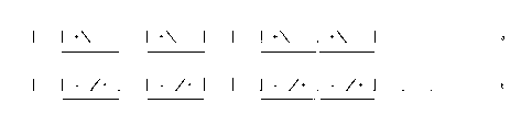
Figure 7 shows a schematic representation of a method of droplet
deposition in accordance with a first embodiment of the present invention.
There
is displayed a line of image data pixels, which in this particular embodiment
are
either black or white. This line of image data pixels is then `screened' or
converted into a series of commands for the array of actuators pictured in
Figure
7. The fluid chambers of the actuator are shown schematically in Figure 7,
with
vertical lines representing the channel separating walls.
Pairs of fluid chambers are selected according to the screening procedure,
the locations of these pairs corresponding to the positions of the `black'
image
pixels. For each pair of fluid chambers, the central dividing wall is
actuated, as
shown in Figures 8 and 9, moving backwards and forwards between the
chambers so as to release a pair of droplets onto the substrate.
As will be apparent from the figure, all the pairs are separate and distinct,
so that each fluid chamber is a member of at most one pair. In this way, the
actuations within each pair may be physically isolated from actuations in
other
pairs. The pairs may be spaced apart by any number of non-firing chambers, but
the use of the invention is indicated by the spacing apart of pairs of firing
chambers by an odd number of non-firing chambers. This will, in general,
produce a pattern of dots disposed on a grid on the substrate where two
regions
of regularly spaced dots, each region consisting of an even number of dots,
are
separated by a gap on the grid corresponding to the absence of an odd number
CA 02748138 2011-05-11
WO 2010/055344 PCT/GB2009/051526
-13-
of dots. This includes, for example, the situation where a black-black-white-
black-black pattern is formed on the substrate.
The period of oscillation of the wall may advantageously be less than the
relaxation time of the chamber so as to use the residual acoustic wave energy
from previous wall movements to assist droplet release. Each of these active
pairs is represented in Figure 7 by a horizontal line beneath the two chambers
of
the pair; the remaining, inactive chambers are represented by an X. The active
pairs will correspond to a pair of dots in the pattern created on the
substrate.
In more detail, Figures 8 and 9 both show two different methods of
actuating the walls of the chambers so as to form a representation of the
image
in Figure 7. In both methods the outer walls of a pair do not directly cause
droplet ejection but are used for a different purpose, such as reinforcing
ejection,
preventing fluid stagnation, or reducing cross-talk.
Figures 8(a) and 8(b) show the walls of the chambers at two different
points in time separated by one half of the actuation cycle. It is therefore
apparent that the central dividing walls of the selected pairs are actuated,
while
the remaining walls are not actuated. Thus the outer walls of each pair remain
substantially still and undeformed during actuation of the central wall. In
this
way, the outer walls act as a barrier to pressure disturbances caused by the
actuation of the central wall, thus preventing cross-talk with chambers
outside of
the pair. In a construction where a single electrode addresses each channel,
it is
therefore a requirement that identical signals be applied to the channel
electrodes either side of the wall to be held still.
Figures 9(a) and 9(b) also show chambers at two points one half-cycle
apart, but in an actuation scheme where all walls are actuated. According to
this
embodiment, all the walls of non-firing chambers - and thus the outer walls of
the
selected pairs - are constantly actuated in phase. This motion prevents the
stagnation of fluid within the non-firing chambers, which might otherwise lead
to
the blockage of the apertures of those chambers. The separating wall of the
firing pair moves in opposition to this motion so as to cause ejection from
each
CA 02748138 2011-05-11
WO 2010/055344 PCT/GB2009/051526
-14-
chamber, with the additional energy imparted by the non-firing walls
reinforcing
the firing actuation.
It will be apparent that where three black image pixels appear together
these may be screened as either one or two active pairs. In the embodiment of
Figure 7, the three pixels are represented by two active pairs, with the extra
droplet filling one of the spaces corresponding to the two blank pixels in the
image. The screening procedure may take account of the amount of
neighbouring blank space so as to ensure that the error is less visible in the
printed pattern - for example, it may prevent single `white' image pixels from
being represented as with a droplet. It will be appreciated that in this
embodiment the narrowest region of print available is two droplets wide, but
it
has been found that the resultant degradation in printed image quality is
often
negligible.
For example, Figures 12 and 13 show respectively the character `A' and
the edge of a circle when screened into a plurality of pairs of print pixels.
It will
be apparent that the error in this conversion is negligible even at this level
of
magnification and so the errors in the pattern formed on the substrate are
unlikely
to be perceptible. In some cases, the image may be pre-processed so as to
optimise it for such a printing method. For example, where text is to be
printed,
optimised fonts may be used.
In situations in which it is not possible to deposit only one droplet from a
pair there will be an inherent error in representing a single pixel as either
a pair of
droplets or no droplets at all. The screening algorithm may transfer this
error to
adjacent lines of image data in an error distribution process such as
dithering.
By contrast to some previously suggested actuation schemes, the
actuation may advantageously occur at sufficiently high frequency that fluid
droplets are released from the two chambers with a time difference less than
the
relaxation time for the chambers. The Applicant has recognised that where
chambers are paired in this manner, the residual pressure waves produced when
a wall moves towards a first chamber may be used advantageously to perturb the
CA 02748138 2011-05-11
WO 2010/055344 PCT/GB2009/051526
-15-
meniscus at the aperture of the second chamber in the pair. By moving the
dividing wall towards the second chamber at an appropriate time the pressure
waves - rather than causing interference or `cross-talk' - thus encourage
controlled fluid release.
Preferably the time period taken for the wall to move from the first
chamber to the second and then return - the actuation period - is chosen to
lie in
the range of 0.5 to 1.5 acoustic periods. As may be seen from Figure 2 it is
at
this point that the pressure in the second chamber is at or near a maximum,
thus
favouring controlled ejection. It may be preferable to utilise an actuation
period
close to, but differing from the acoustic period so as to avoid resonant
behaviour
within the chamber. It has been found that actuating at resonance may in some
circumstances cause fluid droplets to be released with ever increasing speeds,
thus leading to unstable droplet deposition.
As mentioned above, the acoustic period for a chamber may be
determined by providing a single impulse to a chamber by a single movement of
an actuating wall towards that chamber: the period of pressure oscillations
within
the chamber is the acoustic period. For a long, thin chamber or channel of
length
L the acoustic period is approximately L/c, where c is the speed of sound in
the
fluid.
Figure 15 displays a voltage waveform that may be applied across a
separating wall in the embodiments shown in figures 7 to 11. In the case of an
electrode structure as described with reference to Figure 1, this waveform
corresponds to the potential difference between the signals at the adjacent
channel electrodes. Where it is desired to produce a bipolar voltage across a
wall with such a construction, this may be accomplished by applying one uni-
polar signal to each of the neighbouring electrodes, so that one signal
provides
positive portions of the voltage across the wall and the other signal provides
negative portions.
There is a direct relationship between the voltage and the position of the
wall: where the voltage is held at zero the wall is undeformed; where the
voltage
CA 02748138 2011-05-11
WO 2010/055344 PCT/GB2009/051526
-16-
is held at a positive value the wall is deformed towards the first chamber and
where the voltage is held at a negative value the wall is deformed towards the
second chamber. The movement of the wall will tend to lag behind the voltage
signal owing to the response time of the system.
The signal applied across the dividing wall comprises two square wave
portions: a first, positive portion that causes the wall to move from its
undeformed
state towards the first chamber and then return to its undeformed state; and a
second, negative portion that causes the wall to move from its undeformed
state
towards the second chamber and again to return to its undeformed state. Where
the time spacing between first and second portions is of a similar magnitude
to
the response time of the system the wall may move directly from deformation
towards the first chamber to deformation towards the second chamber with no
appreciable pause in its undeformed state, and may thus be considered a single
continuous movement from first chamber to second.
As is shown in Figure 14, the beginning of the second square wave portion
is one acoustic length after the beginning of the first square wave. It is
apparent
from Figure 2 that this enables the movement of the wall towards the second
chamber to be to an extent coincident with a pressure maximum in the second
chamber caused by the first pulse.
In more detail, the initial deformation towards the first chamber will cause
an instantaneous increase in the pressure of the first chamber and a decrease
in
the pressure of the second chamber, but will also create inwardly moving
positive
pressure acoustic waves at the open ends of the second channel. These
acoustic waves will travel inwards and converge upon the nozzle of the second
channel after half an acoustic period (half an acoustic period corresponds to
the
time taken for the waves to reach the centre of the channel, where the nozzle
is
located). This point corresponds to the pressure maximum shown in Figure 2.
The dividing wall then moves back towards the second channel to
instantaneously increase the pressure in the second channel and decrease the
pressure in the first channel. The combination in the second channel of the
CA 02748138 2011-05-11
WO 2010/055344 PCT/GB2009/051526
-17-
positive acoustic wave present at the nozzle and the positive pressure
generated
by the wall movement is sufficient to cause release of a droplet.
Given suitable flexibility in the drive electronics producing such voltage
signals it is possible to alter the relative speeds of the fluid droplets
produced by
the first and second chambers. For example, in the voltage waveform of Figure
14 both the amplitude and the length of the second square wave portion is
greater than that of the first square wave portion. During operation, the
array of
fluid chambers is moved relative to a substrate during deposition of fluid
droplets
on that substrate; with suitable alteration of the parameters of the square
waves it
is possible to ensure that the difference in droplet speeds counterbalances
the
difference in timing of the release of the droplets. Thus it is possible to
ensure
that - for a given speed of movement - the droplets are deposited so as to
form
dots on a single straight line on the substrate.
There may, of course, remain some small offset of the dots in the direction
of relative movement of the substrate and the apparatus, but this will be
small
when compared to the diameter of the dot formed, or at the least there will
not be
space separating the dots in the substrate movement direction.
Conversely, there may exist situations where it is, in fact, desirable to have
an appreciable gap between the dots formed by the droplets on the substrate.
The thus formed dots will lie on line at an angle to the direction of
substrate
movement. The dots formed by pairs within the array may nonetheless be
aligned in a print line direction on the substrate, with the dots within each
pair at
an angle to the print line direction so that an image may therefore be formed
from
a plurality of `diagonal pixels'. The angle may preferably be 30 or 45
degrees,
and - in some embodiments - the angle may differ between pairs. These
`diagonal pixels' may advantageously be arranged and spaced so that printing
from all chambers results in a checkerboard pattern. Such an arrangement may
prove useful in forming shading or dithering patterns.
Further, such flexibility may also allow different volumes of fluid to be
ejected from the two chambers; this may for example be accomplished by
CA 02748138 2011-05-11
WO 2010/055344 PCT/GB2009/051526
-18-
altering the relative amplitudes and timings of the two first and second
square
waves. As each pair of chambers is effectively an isolated system, they may be
considered separately, and so once a waveform is developed that allows a pair
to
release droplets of two specific volumes, this same waveform may also be
applied to other pairs within the array at substantially the same time, so
that the
actuations of the pairs all overlap in time.
Furthermore, a `family' of waveforms may be developed, each producing a
pair of dots on the substrate with specific sizes. Pairs may then be selected
within the array using a screening procedure and an appropriate one of the
family
of waveforms selected so as to produce two dots having appropriate sizes. As
each pair of channels is isolated, the method will advantageously allow for
the
use of the same family of waveforms for any pair of chambers in the array
whilst
cross-talk is substantially prevented.
Further still, each member of the family of waveforms may be designed in
such a way that the speeds of two such droplets of different volumes are
adjusted to align their landing positions perpendicular to the direction of
substrate
movement.
Such a `family' of waveforms allows each pair to form dots on the
substrate having various combinations of dot sizes, dot sizes being known in
the
art as grey-levels. The screening processes displayed in figures 7 and 10 may
be adapted to take account of the number of grey-levels available for each
chamber in a pair.
It will be appreciated by those skilled in the art that while the methods
displayed in figures 7 and 10 concern just black and white pixels (a binary
image), the method may easily be extended to pixels having any number of grey-
levels. This of course holds true even for situations where it is only
possible to
deposit a pair of droplets of the same size, though the amount of error that
the
screening process must distribute will be much greater. As will be apparent,
the
greater flexibility in the droplet volumes of a pair, the smaller the error
will be that
CA 02748138 2011-05-11
WO 2010/055344 PCT/GB2009/051526
-19-
must be distributed so that the difference will be one of degree rather than
principle.
Figure 15 shows a voltage signal adapted for use in a method according to
a still further embodiment of the present invention. Whereas the embodiment of
Figure 14 consisted of only one positive square wave portion and one negative
square wave portion, the present embodiment consists of a plurality of such
square wave portions. The square waves each cause the release of a droplet of
fluid from the apertures of the respective fluid chambers to form a growing
train of
conjoined droplets at the aperture, but crucially do not impart sufficient
energy to
cause the break-off of the train until the final actuation.
According to this embodiment the number of square waves may thus be
approximately proportional to the total volume of the train of droplets, with
each
successive square wave adding a further quantum of fluid; this again allows
the
development of a `family' of waveforms having a range of dot sizes. In this
particular embodiment the family may be constrained so that the number of
positive and negative square wave portions may differ by at most one. This
will
cause an image formed using such a technique to consist of pixels having the
width of two droplets, but with variable tone.
In such embodiments, each pair will alternate between releasing droplets
of fluid from one chamber in the pair and the other chamber in the pair. The
actuations for all pairs are made to overlap in time so as to minimise the
length of
a firing cycle. Each train of thus-released droplets will form a separate dot
on the
substrate, with the print weight or print density of the dot being positively
related
to the number of droplets making up the dot.
In order to synchronise actuations between pairs in the array there will be
a predetermined maximum number of droplets N that each firing chamber may
eject as a single train. It may be arranged that actuations for all pairs are
aligned
in time, for example so that the first or last droplets released by each pair
are
released simultaneously.
CA 02748138 2011-05-11
WO 2010/055344 PCT/GB2009/051526
-20-
In more detail, the positive square wave portions shown in the embodiment of
Figure 15 are of shorter duration that the negative square wave portions and
so
impart less energy to the droplet growing at the first nozzle. The widths of
the
square wave portions are chosen as described above to ensure that the droplets
released from the two chambers are aligned on the substrate.
Figure 16 shows a further voltage signal adapted for use in a method
according to yet a further embodiment of the present invention. The signal is
substantially the same as that shown in Figure 15 but with substantially
similar
positive and negative square wave portions. In this embodiment, the square
waves are preceded by a shorter negative square wave pulse which does not
immediately lead to ejection but generates acoustic waves within the second
chamber that increase the energy of the droplet released from the second
chamber. This extra energy may be utilised to align the two dots on the
substrate, or, as mentioned above, to produce a controlled spacing between the
two dots.
Further embodiments of the present invention may combine the variable
pulse sizes of the embodiment displayed in Figure 14 with the variation in
number of pulses shown in Figure 15. This will again enable the two dots
produced by the pair of chambers to be aligned on the substrate, or for their
spacing to be suitably controlled.
In still further embodiments, a firing chamber will always release the same
number of droplets, and thus the size of the dots formed on the substrate is
essentially fixed. While this clearly will not afford a variety of dot sizes
to be
produced on the substrate, as it results essentially in a binary printing
process, it
has been found that, in many cases, a train of droplets of a given volume will
be
formed and travel to the substrate more reliably than a single droplet of the
same
volume. Thus, where binary printing is acceptable, such a process will provide
improved reliability with an attendant increase in printing through-put common
to
all embodiments.
CA 02748138 2011-05-11
WO 2010/055344 PCT/GB2009/051526
-21 -
While the above exemplary embodiments make reference to waveforms
comprising square wave portions, it will be appreciated by those skilled in
the art
that waveform portions of various forms such as triangular, trapezoidal, or
sinusoidal waves may be used as appropriate depending on the particular
deposition apparatus.
As is discussed above, the present invention may be applied to both `side-
shooter' or `end-shooter' type apparatus and more generally to any apparatus
having an array of chambers separated by actuable walls.
Further, where reference is made to the grey-level of a pixel, it will be
appreciated that this does not necessarily imply the use of black ink, nor of
a
pigment of any kind. For example a colour image may be considered a
combination of cyan, magenta, yellow and black images and the tone of each
pixel represented by a `grey-level' in each of these four colours. More
generally
still, with regards to the fluid droplets, grey-level is only intended to
represent the
volume of the droplet and does not concern the nature of the fluid itself. Of
course, while the invention may have particular benefit in graphics
applications
where a printed image is formed of pigment or ink using an inkjet printer, the
advantages of the present invention will be afforded with many types of
droplet
deposition apparatus, substrate and ejection fluids, including the use of
functional
fluids capable of forming electronic components, uniform coating of large
areas
(e.g. varnishes) and the fabrication of 3 dimensional components.