Language selection

Search

Patent 2748435 Summary

Third-party information liability

Some of the information on this Web page has been provided by external sources. The Government of Canada is not responsible for the accuracy, reliability or currency of the information supplied by external sources. Users wishing to rely upon this information should consult directly with the source of the information. Content provided by external sources is not subject to official languages, privacy and accessibility requirements.

Claims and Abstract availability

Any discrepancies in the text and image of the Claims and Abstract are due to differing posting times. Text of the Claims and Abstract are posted:

  • At the time the application is open to public inspection;
  • At the time of issue of the patent (grant).
(12) Patent: (11) CA 2748435
(54) English Title: NON-PRESSURIZED SYSTEM FOR CREATING LIQUID DROPLETS IN A DENTAL CLEANING APPLIANCE
(54) French Title: SYSTEME NON PRESSURISE PERMETTANT DE CREER DES GOUTTES DE LIQUIDE DANS UN APPAREIL DE NETTOYAGE DENTAIRE
Status: Deemed expired
Bibliographic Data
(51) International Patent Classification (IPC):
  • A61C 1/00 (2006.01)
  • A61C 15/00 (2006.01)
  • A61C 17/02 (2006.01)
  • A61C 17/028 (2006.01)
(72) Inventors :
  • EDWARDS, DAINIA (Netherlands (Kingdom of the))
  • KLOSTER, TYLER G. (Netherlands (Kingdom of the))
  • BENNING, WOLTER F. (Netherlands (Kingdom of the))
(73) Owners :
  • KONINKLIJKE PHILIPS ELECTRONICS, N.V. (Not Available)
(71) Applicants :
  • KONINKLIJKE PHILIPS ELECTRONICS, N.V. (Netherlands (Kingdom of the))
(74) Agent: SMART & BIGGAR LLP
(74) Associate agent:
(45) Issued: 2017-05-09
(86) PCT Filing Date: 2009-12-04
(87) Open to Public Inspection: 2010-07-08
Examination requested: 2014-12-01
Availability of licence: N/A
(25) Language of filing: English

Patent Cooperation Treaty (PCT): Yes
(86) PCT Filing Number: PCT/IB2009/055518
(87) International Publication Number: WO2010/076694
(85) National Entry: 2011-06-27

(30) Application Priority Data:
Application No. Country/Territory Date
12/344,852 United States of America 2008-12-29

Abstracts

English Abstract


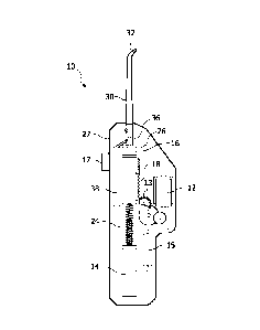
The appliance (10, Figure 1) includes a body portion (27) and
a nozzle portion (30) through which a spray of liquid droplets exits from a
distal end thereof for cleaning of dental regions. The nozzle includes an ori-
fice
(36) at a proximal end thereof adjacent the body portion, as well as a
pump (38) for moving liquid into an area of the nozzle just forward of the ori-
fice.
A mechanical system (12, 13, 14) is provided for moving a plunger or
piston element (16) first away from the orifice under tension, such as a com-
pression
spring(24), and then controllably releasing the plunger or piston to-ward
the orifice, the plunger/piston moving with sufficient force that atmo-spheric

air which has been drawn into the appliance between the plunger or
piston is forced through the orifice at a sufficiently high rate of speed to
pro-duce
a spray of fluid droplets for dental cleaning when the moving air comes
into contact with the liquid in the nozzle.


French Abstract

La présente invention concerne un appareil (10, figure 1) comportant une partie corps (27) et une partie buse (30), à travers laquelle une pulvérisation de gouttelettes de liquide est émise, à partir d'une extrémité distale correspondante, pour le nettoyage de régions dentaires. La buse comporte un orifice (36) situé au niveau d'une extrémité proximale correspondante adjacente à la partie corps, ainsi qu'une pompe (38) permettant de déplacer le liquide en direction d'une zone de la buse située immédiatement en amont de l'orifice. Un système mécanique (12, 13, 14) permet de déplacer un élément plongeur ou piston (16), d'abord en l'éloignant de l'orifice sous l'action d'une tension, notamment d'un ressort de compression (24), puis de relâcher de manière contrôlée ledit plongeur ou piston en direction de l'orifice, le plongeur/piston se déplaçant alors avec une force suffisante pour que l'air atmosphérique, aspiré dans l'appareil entre ledit plongeur ou piston, est forcé à travers l'orifice à une vitesse suffisamment élevée pour produire une pulvérisation de gouttelettes de liquide permettant le nettoyage dentaire lorsque l'air en déplacement entre en contact avec le liquide dans la buse.

Claims

Note: Claims are shown in the official language in which they were submitted.


5
CLAIMS:
1. A fluid droplet appliance for dental cleaning, comprising:
a dental cleaning appliance having a body portion and a nozzle portion for
exit
of a spray of liquid droplets from a distal end thereof;
a liquid reservoir wherein in operation liquid is moved from the reservoir
into
an area of the nozzle near an open proximal end thereof;
a system for driving a plunger or piston element toward the proximal end of
the
nozzle with sufficient force that air acted on by the plunger or piston
element is forced or
released into the nozzle at a high rate of speed, sufficient to create a spray
of liquid droplets
when the moving air comes into contact with the liquid;
an orifice at a proximal end of the nozzle portion, through which air is
forced
by action of the plunger or piston element; and
a motor, a battery for the motor and a gear train, including a drive gear
which
mates with a gear rack on the plunger or piston element,
wherein movement of the drive gear moves the plunger rearwardly of the
appliance against a compression spring, wherein the plunger is released upon
reaching a
certain position relative to the compression spring, moving air through the
orifice.
2. The fluid droplet appliance of claim 1, wherein the drive gear includes
an open
section on its periphery, and wherein when that the open section comes into
position adjacent
the gear rack on the plunger or piston element, there is no engagement between
the plunger or
piston element, and the plunger or piston element is released.
3. The fluid droplet appliance of claim 1, wherein the appliance includes a
user-
operated element to actuate the appliance.

6
4. The fluid droplet appliance of claim 1, wherein atmospheric air is drawn
into
the appliance by action of the plunger or piston element being moved away from
the orifice.
5. The fluid droplet appliance of claim 4, wherein air is drawn into the
appliance
through the orifice or through a one-way valve in the body of the appliance.
6. The fluid droplet appliance of claim 1, wherein the orifice is within
the range
of 0.5-10 mm in diameter.
7. The fluid droplet appliance of claim 1, wherein the velocity of the
liquid
droplets from the distal end of the nozzle is within the range of 10-200
meters per second.

Description

Note: Descriptions are shown in the official language in which they were submitted.


CA 02748435 2016-06-02
64869-1611
1
NON-PRESSURIZED SYSTEM FOR CREATING
LIQUID DROPLETS IN A DENTAL CLEANING APPLIANCE
This invention relates generally to liquid droplet dental cleaners, and more
specifically concerns a non-pressurized system for creating a droplet spray
for dental cleaning.
Dental cleaners using a spray of liquid droplets to clean dental regions of
the
teeth, including interproximal areas, are known. In many such appliances, a
stream of high
velocity gas is used to create the liquid droplets when liquid is brought into
contact with the
gas stream, such as by a pump or other arrangement.
Typically, the high velocity gas stream uses compressed gas, such as from a
cartridge source, to provide the energy necessary for the gas stream. A
compressed gas
appliance is generally effective to produce liquid droplets for cleaning.
However, compressed
gas does have known limitations, including safety limitations and objections
by some users to
the taste of the resulting liquid droplets. The depleted gas cartridges must
also be disposed of
safely and in an environmentally appropriate manner, which can be
inconvenient.
Hence, it would be desirable to have a liquid droplet dental appliance which
is
capable of producing liquid droplets for cleaning with a non-pressurized
source of gas, in
particular without the need for a compressed gas consumable cartridge.
Accordingly, one aspect of the invention is a fluid droplet appliance for
dental
cleaning, comprising: a dental cleaning appliance having a body portion and a
nozzle portion
for exit of a spray of liquid droplets from a distal end thereof; a liquid
reservoir wherein in
operation liquid is moved from the reservoir into an area of the nozzle near
an open proximal
end thereof; a system for driving a plunger or piston element toward the
proximal end of the
nozzle with sufficient force that air acted on by the plunger or piston
element is forced or
released into the nozzle at a high rate of speed, sufficient to create a spray
of liquid droplets
when the moving air comes into contact with the liquid; an orifice at a
proximal end of the
nozzle portion, through which air is forced by action of the plunger or piston
element; and a

CA 02748435 2016-06-02
64869-1611
la
motor, a battery for the motor and a gear train, including a drive gear which
mates with a gear
rack on the plunger or piston element, wherein movement of the drive gear
moves the plunger
rearwardly of the appliance against a compression spring, wherein the plunger
is released
upon reaching a certain position relative to the compression spring, moving
air through the
orifice.

CA 02748435 2011-06-27
WO 2010/076694 PCT/1B2009/055518
2
Figure 1 is a schematic view of a first embodiment of a non-pressurized liquid

droplet appliance.
Figure 2 is a schematic view of another embodiment.
Figure 3 is a schematic view of another embodiment.
Figure 1 shows an appliance 10 which uses a mechanical spring-drive system to
create a liquid droplet spray for dental cleaning. The appliance includes a
motor and gear train
arrangement 12, with a drive gear 13, the motor being powered by a battery 14.
A control unit
15 is included between the battery and the motor for control of the operation
of the appliance. A
button or similar element 17 is used to actuate the appliance. The gear train
drives a
plunger/piston member 16 with drive gear 13 engaging a gear rack 18 on
plunger/piston 16. As
the drive gear 12 rotates, plunger/piston 16 is moved to the rear of the
appliance 10 against the
action of a compression spring 24. At the same time, air is drawn into a
chamber 26 in the
appliance, which could be the interior of the appliance, or a separate volume
within the interior
of the appliance.
The appliance includes an elongated nozzle 30 which extends outwardly from the

appliance and typically has a curved portion 32 at the distal end thereof,
through which a spray
of liquid droplets is directed for cleaning action against dental regions of
the teeth. The curved
portion 32 assists in convenient positioning of the nozzle 30 in the mouth by
the user. At a
proximal end of the nozzle adjacent body 27 of the appliance is an orifice 36.
Orifice 36 can
vary in size, typically between 0.5 mm and 10 mm. As indicated above, when the
plunger/piston
16 is moved to the rear by the action of the motor and gear train 12, air is
drawn into chamber
26, either through orifice 36 or alternatively, through a one-way check valve
in the body 27 of
the appliance, which communicates with chamber 26.
A reservoir 38 for water or other liquid is also present in the appliance.
Liquid in
reservoir 38 is moved to the vicinity of the orifice 36 within the nozzle,
typically by a pump or
by passive aspiration or other means.

CA 02748435 2011-06-27
WO 2010/076694 PCT/1B2009/055518
3
Drive gear 13 in the embodiment shown has an open space (teeth missing) at a
selected position on its periphery, such that when the open space comes
adjacent the gear rack 18
on the plunger/piston, the plunger releases, since there are no meshed gears
to hold it back, at
high speed toward orifice 36 by the action of compression spring 24 moving
toward its rest (non-
compressed) position. This action is sufficient to drive the air in chamber 26
at high speed
through orifice 36. When the fast-moving air comes into contact with the
liquid which is
adjacent orifice 36, a spray of liquid droplets is produced.
The liquid droplets can be of various sizes, and the speed of the droplets can
vary
from relatively low speed, e.g. 10 meters per second, to a high speed of 200
meters per second
or even greater. Typically, however, a 50 m/sec droplet velocity with droplets
in a size range of
microns-0.5 mm will provide effective dental cleaning.
Figure 2 shows another non-pressurized gas drive embodiment, generally
referred
to as a voice coil drive. The appliance is shown generally at 50. It includes
a body portion 52
and a nozzle portion 54 which extends forwardly from the body portion. Body
portion 52
includes an actuating element 72. Positioned within body portion 52 are a
water reservoir 56 and
a battery and circuit (electronics) portion 58. The battery and circuit
portion 58 connects to a
voice coil assembly 60, providing an energizing signal thereto. The battery
and circuit portion
58 includes a capacitor 62. Voice coil 60 encircles a magnet 64. Connected to
magnet 64 and
positioned between magnet 64 and the proximal end of nozzle portion 54 is a
piston 66. At the
proximal end 68 of nozzle portion 54, adjacent body portion 52, is a nozzle
orifice 70. Orifice
70 is typically 0.5-10 mm in diameter.
In operation in one arrangement, the user operates button 72. This energizes
the
voice coil 60, which pulls magnet 64 rearwardly, which in turn pulls piston 66
toward the rear of
the appliance. When the piston is moved rearwardly, air moves into the
interior of the body
portion 52, either through orifice 70 or through a one-way valve in the body
portion. The air
could move into the interior of the appliance, or into a chamber within the
appliance. The
capacitor 62 also begins to charge. When the charge reaches a certain
preselected level, the

CA 02748435 2011-06-27
WO 2010/076694 PCT/1B2009/055518
4
capacitor discharges into the voice coil which drives the magnet forward,
pushing the piston
toward the orifice.
In another arrangement, the voice coil maintains the magnet and the piston in
a
rear position prior to operation of button 72. When button 72 is operated, the
capacitor begins to
charge, until it reaches a selected charge level, at which point the capacitor
discharges into the
voice coil, which drives the magnet and the piston forwardly.
Sufficient force is produced by the piston in each arrangement to force air at
high
speed through orifice 70. The air forced through the orifice contacts liquid
which is directed into
the lower end of the nozzle through line 73 by means of a pump or the like.
Droplets are created
by the interaction of the fast-moving air and the liquid. The droplets created
will vary in size. In
this arrangement, the droplets will be, for instance, between 5 microns - 0.5
mm. The gas stream
will further help to move the droplets through the nozzle and out toward the
teeth for cleaning.
In still another arrangement, referring to Figure 3, an appliance 80 includes
in a
body portion 81 a pump 82 which acts on a piston 84 in a cylinder 86, to
compress air to a
specified pressure in a volumetric valve 88. Operation is initiated by a
button 87; power is
provided by a battery 91. When a specified pressure is reached, the valve is
released, with the
compressed air being forced through an orifice 90 to contact liquid in a lower
portion of a nozzle
portion 92. Droplets are created by the interaction of the fast-moving gas and
the liquid and
move through the exit 94 of nozzle 92.
Accordingly, several embodiments have been described which produce a spray of
liquid droplets through a nozzle for dental cleaning without the use of a
pressurized gas system
and with the use of atmospheric air.
Although a preferred embodiment of the invention has been disclosed for
purposes of illustration, it should be understood that various changes,
modifications and
substitutions can be incorporated in the embodiment without departing from the
spirit of the
invention, which is defined by the claims which follow.

Representative Drawing
A single figure which represents the drawing illustrating the invention.
Administrative Status

For a clearer understanding of the status of the application/patent presented on this page, the site Disclaimer , as well as the definitions for Patent , Administrative Status , Maintenance Fee  and Payment History  should be consulted.

Administrative Status

Title Date
Forecasted Issue Date 2017-05-09
(86) PCT Filing Date 2009-12-04
(87) PCT Publication Date 2010-07-08
(85) National Entry 2011-06-27
Examination Requested 2014-12-01
(45) Issued 2017-05-09
Deemed Expired 2019-12-04

Abandonment History

There is no abandonment history.

Payment History

Fee Type Anniversary Year Due Date Amount Paid Paid Date
Application Fee $400.00 2011-06-27
Maintenance Fee - Application - New Act 2 2011-12-05 $100.00 2011-11-23
Maintenance Fee - Application - New Act 3 2012-12-04 $100.00 2012-11-26
Maintenance Fee - Application - New Act 4 2013-12-04 $100.00 2013-11-28
Maintenance Fee - Application - New Act 5 2014-12-04 $200.00 2014-11-27
Request for Examination $800.00 2014-12-01
Maintenance Fee - Application - New Act 6 2015-12-04 $200.00 2015-11-23
Maintenance Fee - Application - New Act 7 2016-12-05 $200.00 2016-11-29
Final Fee $300.00 2017-03-21
Maintenance Fee - Patent - New Act 8 2017-12-04 $200.00 2017-11-24
Owners on Record

Note: Records showing the ownership history in alphabetical order.

Current Owners on Record
KONINKLIJKE PHILIPS ELECTRONICS, N.V.
Past Owners on Record
None
Past Owners that do not appear in the "Owners on Record" listing will appear in other documentation within the application.
Documents

To view selected files, please enter reCAPTCHA code :


To view images, click a link in the Document Description column. To download the documents, select one or more checkboxes in the first column and then click the "Download Selected in PDF format (Zip Archive)" or the "Download Selected as Single PDF" button.

List of published and non-published patent-specific documents on the CPD .

If you have any difficulty accessing content, you can call the Client Service Centre at 1-866-997-1936 or send them an e-mail at CIPO Client Service Centre.


Document
Description 
Date
(yyyy-mm-dd) 
Number of pages   Size of Image (KB) 
Abstract 2011-06-27 2 81
Claims 2011-06-27 2 77
Drawings 2011-06-27 3 23
Description 2011-06-27 4 186
Representative Drawing 2011-06-27 1 7
Cover Page 2011-09-02 2 46
Claims 2016-06-02 2 53
Description 2016-06-02 5 203
PCT 2011-06-27 8 302
Assignment 2011-06-27 3 90
Prosecution-Amendment 2014-12-01 2 82
Change to the Method of Correspondence 2015-01-15 2 66
Examiner Requisition 2016-01-20 3 228
Amendment 2016-06-02 8 294
Final Fee 2017-03-21 2 74
Representative Drawing 2017-04-12 1 4
Cover Page 2017-04-12 2 46