Note: Descriptions are shown in the official language in which they were submitted.
CA 02748459 2013-11-04
ADAPTIVE VOLTAGE CONTROL FOR WIND TURBINES
FIELD OF THE INVENTION
The present invention generally relates to the field of wind turbines and,
more particularly, to controlling
operation of wind turbines based upon grid conditions.
BACKGROUND
The application of wind-powered generating systems in the past has been on a
small scale when
compared to the total generating capacity of an electrical power grid. A term
that is often used to describe the
relative quantity of wind-generated power is "penetration." Penetration is the
ratio of wind-generated power
to the total available generated power for a power grid. Previously, even in
those locations where
wind-generated power is highest, the penetration levels are under about a few
percent. While this is a
relatively small amount of power, and the rules that govern the operation of
the wind turbines reflect this
small penetration, it is clear that the penetration is increasing and
therefore the operating rules for the wind
turbines will be changing. For example, one operating principle that is being
revised is the required amount of
grid stability support that must be provided by wind turbines. As can be
appreciated, as the penetration of wind
turbines increases, the expectation that they contribute to the stability of
powers grids becomes greater.
Power utilities today face an ever-growing demand for higher quality, reliable
power and increased
transmission capacity. A key to increasing reliability and capacity is
ensuring that grid voltage is properly
regulated. This helps prevent service disruptions, damage to electrical
service equipment, generating plants,
and other components of the power grid, and can help maximize transmission
capacity. Generally, utilities
keep voltage levels stable by maintaining a balance of real power and reactive
power on their transmission
grids.
Almost all bulk electric power is generated, transported, and consumed in
alternating current (AC)
networks. Elements of AC systems supply (or produce) and consume (or absorb or
lose) two kinds of
power: real power and reactive power. Real power accomplishes useful work
(e.g., runs motors and lights
lamps). Reactive power supports the voltages that must be controlled for
system reliability.
In an AC electrical system, voltage and current pulsate (described
mathematically by sine waves)
at the system frequency (in North America this is 60 Hertz, or 60 times per
second; in Europe this is 50 Hz, or
50 times per second). Although AC voltage and current pulsate at the same
frequency, they may peak at
1
CA 02748459 2011-06-28
WO 2010/085987 PCT/EP2009/003139
different times (i.e., they may not be in phase). Power is the algebraic
product of voltage and current. Over
a cycle, power has an average value, called real (or active) power, measured
in watts. There is also a
portion of power with zero average value that is called reactive power,
measured in volt-amperes reactive, or
VARs. The total power is called apparent power, measured in volt-amperes, or
VA. Reactive power has
zero average value because it pulsates up and down, averaging to zero.
Reactive power can be positive or
negative, depending on whether the current peaks before or after voltage. By
convention, reactive power,
like real power, is positive when it is "supplied" and negative when it is
"consumed" or absorbed. Consuming
reactive power tends to lower voltage magnitudes, while supplying reactive
power tends to increase voltage
magnitudes.
Voltage control (keeping voltage within defined limits) in an electric power
system is important for
proper operation of electric power equipment to reduce the potential for
damage such as overheating of
generators and motors, to reduce transmission losses, and to maintain the
ability of the system to withstand
disturbances and reduce the potential of voltage collapse. A voltage collapse
can occur when the system is
trying to serve much more load than the voltage can support. Inadequate
reactive power supply lowers
voltage and, as voltage drops, current must increase to maintain the power
supplied, causing the lines to
consume more reactive power and the voltage to drop further. If current
increases too much, transmission
lines trip, or go off-line, overloading other lines and potentially causing
cascading failures. Further, if voltage
drops too low, some generators will automatically disconnect to protect
themselves. Voltage collapse occurs
when an increase in load or loss of generation or transmission facilities
causes dropping voltage, which
causes a further reduction in reactive power from capacitors and line
charging, and still further voltage
reductions. If the declines continue, these voltage reductions cause
additional elements to trip, leading to
further reduction in voltage and loss of power. The result is a progressive
and uncontrollable decline in
voltage, all because the power system is unable to provide the reactive power
required to supply the reactive
power demand. Therefore, the ability of various components of a power system
to support power grids by
supplying (or consuming) reactive power is an important feature.
Presently, geographically remote areas with high wind power potentials may not
be viable
candidates for wind farms due to limited grid transmission capacity and/or
difficulties for matching the
electrical production with the demand, or more generally, due to a "weak
grid." A weak grid is typically one
where it may be necessary for system designers to take voltage level and
voltage fluctuations into account
because there is a probability that the values might exceed the requirements
of the standards set by the
utilities when load and power production cases are considered. Weak grids are
usually found in more
remote places and in areas that were designed for relatively small loads.
For wind energy systems, one problem with weak grids is the variable voltage
levels on the grid
over the course of certain time periods. For example, the voltage level for a
weak grid may vary throughout
the day by several percent due to variable consumer loads. Furthermore, the
connection of wind turbines to
a weak grid tends to increase the voltage level due to the additional active
power production by the wind
turbines. Therefore, in cases where the consumer loads are low (i.e., the
voltage level on the grid is
2
CA 02748459 2011-06-28
WO 2010/085987 PCT/EP2009/003139
relatively high), the connection of wind turbines to the power grid may cause
the voltage levels to rise above
maximum levels required by the standards, which is at a minimum undesirable
and oftentimes unacceptable.
SUMMARY
The present invention at least generally relates to configuring and/or
operating a wind turbine to
adaptively control a voltage of a power grid. In one or more embodiments, a
method and system for
recognizing a condition of a power grid (e.g., fluctuations caused by variable
consumer loads on a weak
grid), and adaptively adjusting a voltage control scheme to substantially
"ignore" voltage changes caused by
the condition are provided. In this regard, the amount of reactive power
consumed by the wind turbine may
be minimized or reduced. Additionally, other features of the present invention
include voltage control with
active power derating for wind turbines and power factor control with active
power derating for wind turbines.
Various aspects of the present invention will now be described. Although each
of the following aspects may
relate or be applicable to the foregoing, the content of this introduction is
not a requirement for any of these
aspects unless otherwise noted.
A first aspect of the present invention is embodied by a wind turbine that may
be electrically-
connected to a power grid, wherein the wind turbine includes a synchronous
generator. The wind turbine
may be configured and operated so as to selectively control a reactive power
characteristic of the
synchronous generator according to a control scheme when the wind turbine is
electrically-connected with
the power grid. Additionally, the wind turbine may be configured to recognize
a predefined condition of the
power grid (which hereafter may be referred to as a "predefined power grid
condition"), and in response to
recognizing such a predefined power grid condition, to modify its control
scheme so as to reduce the amount
of reactive power absorbed by the synchronous generator.
A number of feature refinements and additional features are applicable to the
first aspect of the
present invention. These feature refinements and additional features may be
used individually or in any
combination. The following discussion is separately applicable to the first
aspect, up to the start of the
discussion of a second aspect of the present invention.
In an embodiment of the first aspect, the predefined power grid condition is
in the form of
fluctuations in a voltage of the power grid due to consumer loads associated
with the power grid. As an
example, the fluctuations may be substantially periodic, and may have a period
of a day, a week, a season,
a year, or some other period. In the case where the fluctuations are periodic
and have a period of one day,
the fluctuations may be due to varying consumer loads on a weak power grid.
In one or more embodiments of the first aspect, the recognition of the
predefined power grid
condition may include measuring and/or analyzing a reactive power
characteristic (e.g., reactive power
absorbed or produced) of the synchronous generator for a period of time. As
can be appreciated, a reactive
power characteristic may be indicative of a voltage characteristic of the
power grid (e.g., more reactive
power may be consumed by the synchronous generator when the voltage of the
power grid is too high). In
this regard, the recognition of the predefined power grid condition may
include applying a proportional-
3
CA 02748459 2011-06-28
WO 2010/085987 PCT/EP2009/003139
integral (P1) controller to a reactive power characteristic of the synchronous
generator. Further, the
recognition of the predefined power grid condition may include subtracting a
nominal reactive power
characteristic from a measured reactive power characteristic of the
synchronous generator. In this regard,
the recognition of the predefined power grid condition may entail at least
substantially "ignoring" a reactive
power characteristic that is equal to or less than the nominal reactive power
characteristic.
In one or more embodiments of the first aspect, the modification of the
control scheme of the wind
turbine may include generating an adapted control reference, and providing the
adapted control reference to
the control scheme. For example, the adapted control reference may be created
by generating a first
voltage reference dependent upon a measured reactive power characteristic of
the synchronous generator
and adding a nominal voltage reference (e.g., 100% of a rated voltage) to the
first voltage reference to
generate the adapted voltage reference. In this regard, the wind turbine may
be configured to receive or
otherwise utilize the adapted voltage reference, to measure or otherwise
utilize a voltage of the power grid,
and to selectively control a reactive power characteristic of the synchronous
generator such that the
measured voltage of the power grid substantially tracks the adapted voltage
reference. As an example, the
reactive power characteristic may be selectively controlled by adjusting a
rotor current of the synchronous
generator to reduce the amount of reactive power absorbed by the synchronous
generator. As can be
appreciated, the wind turbine operation may be configured to selectively
control the reactive power
characteristic at a rate that is greater than the rate which the adapted
voltage reference is updated.
In one or more embodiments of the first aspect, the adapted control reference
may be limited to a
range that is dependent upon a rated voltage of the power grid (e.g., 95% to
105% of the rated voltage of the
power grid). Additionally, in one or more embodiments, the control scheme may
be implemented using an
automatic voltage regulator (AVR). The AVR may be operative to receive a
voltage reference, measure a
voltage of the power grid, and control the voltage of the power grid to track
the voltage reference by
selectively adjusting a rotor current of the synchronous generator. To account
for the grid condition, the
voltage reference may be adapted dependent upon the recognition of the
predefined power grid condition.
A second aspect of the present invention is embodied by a wind turbine that
may be electrically-
connected to a power grid, wherein the wind turbine includes a synchronous
generator. The wind turbine
may be configured to operate in a first active power control mode for a first
condition when the wind turbine
is electrically-connected with the power grid. Further, the wind turbine may
be configured to operate in a
second active power control mode for a second condition when the wind turbine
is electrically-connected
with the power grid, wherein operating the wind turbine in the second active
power control mode provides a
different active power characteristic for the wind turbine than when operating
the wind turbine in the first
active power control mode.
A number of feature refinements and additional features are applicable to the
second aspect of the
present invention. These feature refinements and additional features may be
used individually or in any
combination. The following discussion is separately applicable to the second
aspect, up to the start of the
discussion of a third aspect of the present invention.
4
CA 02748459 2011-06-28
WO 2010/085987 PCT/EP2009/003139
In one or more embodiments of the second aspect, the first active power
control mode includes
operating the synchronous generator at an active power level that is
substantially equal to a rated active
power level of the synchronous generator, and the second active power control
mode includes operating the
synchronous generator at an active power level that is less than the rated
active power level of the
synchronous generator.
In one or more embodiments of the second aspect, the first condition and the
second condition are
each dependent upon a voltage of the power grid or one or more physical
characteristics of the synchronous
generator. As an example, the first condition and second condition may each be
determined by measuring a
voltage of the power grid with the wind turbine being electrically-connected
with the power grid, analyzing
the measured voltage of the power grid, and operating the wind turbine in
either the first active power control
mode or the second active power control mode dependent upon the outcome of
this analysis. The noted
analysis may include comparing the measured voltage with a threshold voltage
reference over a period of
time (e.g., integrating a difference between the measured voltage and the
threshold voltage reference). The
wind turbine may be operated in one of the first active power control mode and
the second active power
control mode dependent upon this comparison.
In one or more embodiments of the second aspect, the active power
characteristic is reduced when
operating in the second active power control mode relative to the first active
power control mode by an
amount that is dependent upon a measured voltage of the power grid. As an
example, the amount that the
active power characteristic is reduced by may be proportional to an integral
of the difference between a
measured voltage of the power grid and a maximum voltage reference.
In one or more embodiments of the second aspect, the first condition and the
second condition are
each dependent upon a power factor reference. The power factor reference may
be provided to the wind
turbine by any suitable entity (e.g., a grid operator, a control algorithm, or
the like). In this case, the first
condition and second condition may be determined by receiving the power factor
reference, comparing the
power factor reference to a power factor capability (e.g., a PQ capability
curve) of the synchronous
generator, and operating the wind turbine in either the first active power
control mode or the second active
power control mode dependent upon this comparison. In one example, the active
power characteristic is
reduced when operating in the second active power control mode relative to the
first active power control
mode by an amount that is dependent upon one or more physical characteristics
of the synchronous
generator.
In one or more embodiments of the second aspect, the first condition and
second condition are
each dependent upon both a power factor reference and a voltage of the power
grid. In this regard, the first
condition and second condition may be determined by measuring a voltage of the
power grid, and then
analyzing the measured voltage of the power grid to generate a first active
power reference. Further, a
power factor reference may be received or otherwise utilized by the wind
turbine, the power factor reference
may be compared to a power factor capability of the synchronous generator
(e.g., by utilizing a lookup table)
to generate a second active power reference, and a minimum active power
reference may be utilized for
5
CA 02748459 2011-06-28
WO 2010/085987 PCT/EP2009/003139
operation of the wind turbine, where that "minimum active power reference" is
the smaller of the first active
power reference and second active power reference. The wind turbine may be
operated in either the first
active power control mode or the second active power control mode dependent
upon which of the first and
second active power references is being utilized.
In one or more embodiments of the second aspect, the wind turbine is operated
in the first active
power control mode when the minimum active power reference is equal to the
rated active power level of the
synchronous generator, and the wind turbine is operated in the second active
power control mode when the
minimum active power reference is less than the rated active power level of
the synchronous generator.
Further, in one or more embodiments, the active power level of the wind
turbine when operating in the
second active power control mode is limited to a predetermined range (e.g.,
about 60% to 100% of a rated
active power level).
In one or more embodiments of the second aspect, the wind turbine may include
a turbine rotor
coupled to the synchronous generator through a torque-regulating gearbox or
"TRG." Such a TRG may
include a combination of a hydraulic or hydrodynamic torque converter and a
planetary gear system (e.g., a
multi-stage, functionally interconnected revolving planetary gear system). In
any case, changing the
operation of the wind turbine between the first active power control mode and
the second active power
control mode may include adjusting operation of the torque regulator. For
example and for the case of a
TRG, the operational adjustment may include adjusting a torque conversion
characteristic of the TRG. In
one or more embodiments, the TRG includes a hydraulic circuit, and the
operational adjustment may include
adjusting a mass flow of hydraulic fluid through the hydraulic circuit.
Further, the TRG may include a
plurality of guide vanes disposed in a guide vanes housing, and the
operational adjustment may include
adjusting a position of the plurality of guide vanes. The operational
adjustment may also be characterized
as adjusting an amount of energy absorbed by the TRG.
A third aspect of the present invention is embodied by a wind turbine that may
be electrically-
connected to a power grid, and more specifically where the wind turbine is
configured to adaptively control a
voltage for a generator of the wind turbine. The wind turbine may be
configured to measure a reactive
power characteristic of the generator over a period of time, and to then
process the reactive power
characteristic measurements to generate a corrected voltage factor. The wind
turbine may be further
configured to add the corrected voltage factor to a nominal voltage reference
to generate an adapted voltage
reference, and where this adapted voltage reference may be provided to an
automatic voltage regulator
(AVR) of the wind turbine.
A number of feature refinements and additional features are applicable to the
third aspect of the
present invention. These feature refinements and additional features may be
used individually or in any
combination. The following discussion is separately applicable to the third
aspect, up to the start of the
discussion of a fourth aspect of the present invention.
In one or more embodiments of the third aspect, the processing of the reactive
power characteristic
measurements to generate a corrected voltage factor includes applying a PI
controller to the reactive power
6
CA 02748459 2011-06-28
WO 2010/085987 PCT/EP2009/003139
measurements. As an example, the PI controller may include a time constant
that is greater than an hour.
Further, the wind turbine may include a synchronous generator, and the AVR may
be operative to adjust the
reactive power characteristic by adjusting a rotor current of the synchronous
generator.
In one or more embodiments of the third aspect, the adapted local voltage
reference range may be
between about 95% and 105% of a rated voltage of the power grid, and the
corrected voltage factor may be
limited to within a predefined range. Further, the wind turbine may be
configured to apply a low pass filter to
the measured reactive power characteristic, so that high frequency
fluctuations may be removed.
Additionally, the wind turbine may be configured to subtract a nominal
reactive power reference from the
measured reactive power characteristic so that, for example, the measured
reactive power characteristic
may be "ignored" when it is below the nominal reactive power reference.
A fourth aspect of the present invention is embodied by a wind turbine that
may be electrically-
connected to a power grid, where the active power delivery for a generator of
the wind turbine is controlled.
The wind turbine may be configured to receive or otherwise utilize a threshold
voltage reference, and
furthermore to measure (or otherwise receive) a voltage of the power grid. The
wind turbine may be
configured to subtract the measured voltage from the threshold voltage
reference to generate a voltage
difference value, and this voltage difference value may be processed by the
wind turbine to generate an
adapted active power reference. Further, the adapted active power reference
may be provided to an active
power controller of the generator.
A number of feature refinements and additional features are applicable to the
fourth aspect of the
present invention. These feature refinements and additional features may be
used individually or in any
combination. The following discussion is separately applicable to the fourth
aspect, up to the start of the
discussion of a fifth aspect of the present invention.
In one or more embodiments of the fourth aspect, the adapted active power
reference may be
limited to within a predetermined range. Further, the processing of the
voltage difference value may include
applying an integrator to the voltage difference value, and the active power
delivery may be reduced by an
amount that is dependent upon this processing. In one example, the threshold
voltage reference may be
between about 101% and 105% of a rated voltage of the power grid.
Additionally, the threshold voltage
reference may be dependent upon a maximum reactive power that can be consumed
by the synchronous
generator when operating at a rated active power.
In one or more embodiments of the fourth aspect, the method may include
reducing an active
power delivery of the generator. In the case where the generator is a
synchronous generator, the wind
turbine may include a turbine rotor coupled to the synchronous generator
through a torque regulator, for
instance the above-noted TRG. In this regard, the reduction of the active
power delivery of the generator
may include adjusting operation of the torque regulator. For example and for
the case of a TRG, the
operational adjustment may include adjusting a torque conversion
characteristic of the TRG. In one or more
embodiments, the TRG includes a hydraulic circuit, and the operational
adjustment of the TRG may include
adjusting a mass flow of hydraulic fluid through the hydraulic circuit.
Further, the TRG may include a
7
CA 02748459 2011-06-28
WO 2010/085987 PCT/EP2009/003139
plurality of guide vanes disposed in a guide vanes housing, and the
operational adjustment of the TRG may
include adjusting a position of the plurality of guide vanes. The operational
adjustment of the TRG may also
be characterized as adjusting an amount of energy absorbed by the TRG.
A fifth aspect of the present invention is embodied by a wind turbine that may
be electrically-
connected to a power grid, where the active power delivery for a generator
(e.g., a synchronous generator)
of the wind turbine is controlled. The wind turbine may be configured to
receive or otherwise utilize a power
factor reference, and furthermore to analyze the power factor reference in
relation to one or more physical
capabilities of the generator. Additionally, the wind turbine may be
configured to generate an adapted active
power reference that is dependent upon the power factor reference and the one
or more physical capabilities
of the generator, and to then provide the adapted active power reference to an
active power controller of the
wind turbine generator.
A number of feature refinements and additional features are applicable to the
fifth aspect of the
present invention. These feature refinements and additional features may be
used individually or in any
combination. The following discussion is separately applicable to the fifth
aspect, up to the start of the
discussion of a sixth aspect of the present invention.
In one or more embodiments of the fifth aspect, the analysis of the power
factor reference may
include comparing the power factor reference with the one or more physical
capabilities of the generator,
and/or limiting the power factor reference to be within a predefined range.
The wind turbine may be
configured to limit the adapted active power reference to be within a
predefined range.
In one or more embodiments of the fifth aspect, the wind turbine may be
configured to reduce an
active power delivery of the generator. In the case where the generator is a
synchronous generator, the
wind turbine may include a turbine rotor coupled to the synchronous generator
through a torque regulator,
such as the above-noted TRG. In this regard, the reduction of the active power
delivery may include
adjusting operation of the torque regulator. For example and for the case of a
TRG, the operational
adjustment may include adjusting a torque conversion characteristic of the
TRG. In one or more
embodiments, the TRG includes a hydraulic circuit, and the operational
adjustment may include adjusting a
mass flow of hydraulic fluid through the hydraulic circuit. Further, the TRG
may include a plurality of guide
vanes disposed in a guide vanes housing, and the operational adjustment may
include adjusting a position
of the plurality of guide vanes. The operational adjustment may also be
characterized as adjusting an
amount of energy absorbed by the TRG.
A sixth aspect of the present invention is embodied by a wind turbine that may
be electrically-
connected to a power grid, where the active power delivery for a generator
(e.g., a synchronous generator)
of the wind turbine may be controlled. The wind turbine may be configured to
receive or otherwise utilize a
threshold voltage reference, and furthermore to measure (or otherwise utilize)
a voltage of the power grid.
The wind turbine may be configured to subtract the measured voltage from the
threshold voltage reference
to generate a voltage difference value, and to then process the voltage
difference value to generate a
voltage mode adapted active power reference. Additionally, the wind turbine
may be configured to receive
8
CA 02748459 2011-06-28
WO 2010/085987 PCT/EP2009/003139
or otherwise utilize a power factor reference, to analyze the power factor
reference in relation to one or more
physical capabilities of the generator, and to generate a power factor mode
adapted active power reference
that is dependent upon the power factor reference and the one or more physical
capabilities of the
generator. Further, the wind turbine may be configured to determine the
minimum between the power factor
mode adapted active power reference and the voltage mode adapted active power
reference to generate a
minimum adapted active power reference, and to then provide the minimum
adapted active power reference
to an active power controller of the wind turbine generator.
A number of feature refinements and additional features are applicable to the
sixth aspect of the
present invention. These feature refinements and additional features may be
used individually or in any
combination. The following discussion is separately applicable to the sixth
aspect, up to the start of the
discussion of a seventh aspect of the present invention.
In one or more embodiments of the sixth aspect, the wind turbine may be
configured to limit each of
the power factor mode adapted active power reference and the voltage mode
adapted active power
reference to within a predetermined range. Further, the processing of the
voltage difference value may
include applying an integrator to the voltage difference value.
In one or more embodiments of the sixth aspect, the threshold voltage
reference may be between
about 101% and 105% of a rated voltage of the power grid, and may be dependent
upon a maximum
reactive power that can be consumed by the synchronous generator when
operating at a rated active power.
In one or more embodiments of the sixth aspect, the active power delivery may
be reduced (i.e.,
derated) by an amount that is dependent upon at least one of the processing of
the voltage difference value
and the subsequent analysis of the same in relation to one or more physical
capabilities of the generator. As
an example, the analysis may include comparing the power factor reference with
the one or more physical
capabilities of the generator. Further, the wind turbine may be configured to
limit the power factor reference
to be within a predefined range.
In one or more embodiments of the sixth aspect, the wind turbine may be
configured to reduce an
active power delivery of the generator. In the case where the generator is a
synchronous generator, the
wind turbine may include a turbine rotor coupled to the synchronous generator
through a torque regulator,
such as the above-noted TRG. In this regard, the reduction of active power
delivery of the generator may
include adjusting operation of the torque regulator. For example and for the
case of a TRG, the operational
adjustment may include adjusting a torque conversion characteristic of the
TRG. In one or more
embodiments, the TRG includes a hydraulic circuit, and the operational
adjustment may include adjusting a
mass flow of hydraulic fluid through the hydraulic circuit. Further, the TRG
may include a plurality of guide
vanes disposed in a guide vanes housing, and the operational adjustment may
include adjusting a position
of the plurality of guide vanes. The operational adjustment may also be
characterized as adjusting an
amount of energy absorbed by the TRG.
A seventh aspect of the present invention is embodied by a wind turbine that
may be electrically-
connected to a power grid, wherein the wind turbine includes a synchronous
generator. The wind turbine
9
CA 02748459 2011-06-28
WO 2010/085987 PCT/EP2009/003139
may be configured to receive or otherwise utilize a reference for a control
scheme, and for the wind turbine
to then operate according to the control scheme dependent upon the reference.
Further, the wind turbine
may be configured to monitor or otherwise receive a characteristic of the
power grid, and to then adapt the
reference dependent upon the characteristic of the power grid.
A number of feature refinements and additional features are applicable to the
seventh aspect of the
present invention. These feature refinements and additional features may be
used individually or in any
combination. A number of the features described above in relation to one or
more of the first through sixth
aspects may be applicable to the seventh aspect of the present invention. For
instance, in one or more
embodiments of the seventh aspect, the characteristic of the power grid may be
indicative of a predefined
power grid condition. The predefined power grid condition may be in the form
of fluctuations in a voltage of
the power grid due to consumer loads associated with the power grid. These
fluctuations may be
substantially periodic, and may have a period of a day, a week, a season, a
year, or some other period. In
the case where the fluctuations are periodic and have a period of one day, the
fluctuations may be due to
varying consumer loads on a weak power grid.
Additionally, in one or more embodiments of the seventh aspect, the process
for adapting the
reference dependent upon the characteristic of the power grid may include
measuring and/or analyzing a
reactive power characteristic (e.g., reactive power absorbed or produced) of
the synchronous generator for a
period of time. As can be appreciated, a reactive power characteristic may be
indicative of a voltage
characteristic of the power grid (e.g., more reactive power may be consumed by
the synchronous generator
when the voltage of the power grid is too high). In this regard, the process
for adapting the reference may
include applying a proportional-integral (PI) controller to a reactive power
characteristic of the synchronous
generator. Further, the process for adapting the reference may include
subtracting a nominal reactive power
characteristic from a measured reactive power characteristic of the
synchronous generator. In this regard,
the process for adapting the reference may entail at least substantially
"ignoring" a reactive power
characteristic that is equal to or less than the nominal reactive power
characteristic.
In one or more embodiments of the seventh aspect, the adapted reference that
is provided to the
control scheme may be created by generating a first voltage reference
dependent upon a measured reactive
power characteristic of the synchronous generator and adding a nominal voltage
reference (e.g., 100% of a
rated voltage) to the first voltage reference to generate the adapted voltage
reference. In this regard, the
wind turbine may be configured to receive or otherwise utilize the adapted
voltage reference, to measure or
otherwise utilize a voltage of the power grid, and to selectively control a
reactive power characteristic of the
synchronous generator such that the measured voltage of the power grid
substantially tracks the adapted
voltage reference. As an example, the reactive power characteristic may be
selectively controlled by
adjusting a rotor current of the synchronous generator to reduce the amount of
reactive power absorbed by
the synchronous generator. As can be appreciated, the wind turbine operation
may be configured to
selectively control the reactive power characteristic at a rate that is
greater than the rate which the adapted
voltage reference is updated.
CA 02748459 2013-11-04
In one or more embodiments of the seventh aspect, the adapted reference that
is provided to the
control scheme may be limited to a range that is dependent upon a rated
voltage of the power grid (e.g., 95%
to 105% of the rated voltage of the power grid). Additionally, in one or more
embodiments, the control
scheme may be implemented using an automatic voltage regulator (AVR). The AVR
may be operative to
receive a voltage reference, measure a voltage of the power grid, and control
the voltage of the power grid to
track the voltage reference by selectively adjusting a rotor current of the
synchronous generator. To account
for a condition of the power grid, the voltage reference may be adapted
dependent upon the recognition of
the predefined power grid condition.
According to one aspect of the invention, there is provided a method for
controlling the active power
delivery for a generator of a wind turbine connected to a power grid, the
method comprising:
receiving a threshold voltage reference;
measuring a voltage of the power grid;
subtracting the measured voltage from the threshold voltage reference to
generate a voltage
difference value;
processing the voltage difference value to generate a voltage mode adapted
active power reference;
receiving a power factor reference;
analyzing the power factor reference in relation to one or more physical
capabilities of the generator;
generating an power factor mode adapted active power reference that is
dependent upon the power
factor reference and the one or more physical capabilities of the generator;
determining the minimum between the power factor mode adapted active power
reference and the
voltage mode adapted active power reference to generate a minimum adapted
active power reference; and
providing the minimum adapted active power reference to an active power
controller of the wind
turbine generator.
In accordance with another aspect of the invention, there is provided a wind
turbine connected to a
power grid, the wind turbine comprising:
a synchronous generator electrically connected to the power grid; and
control logic that is configured to:
receive a threshold voltage reference;
receive a measured voltage of the power grid;
subtract the measured voltage from the threshold voltage reference to generate
a voltage
difference value;
process the voltage difference value to generate a voltage mode adapted active
power
reference;
receive a power factor reference;
analyze the power factor reference in relation to one or more physical
capabilities of the generator;
11
CA 02748459 2013-11-04
generate an power factor mode adapted active power reference that is dependent
upon the
power factor reference and the one or more physical capabilities of the
generator;
determine the minimum between the power factor mode adapted active power
reference and
the voltage mode adapted active power reference to generate a minimum adapted
active power reference; and
provide the minimum adapted active power reference to an active power
controller of the wind turbine generator.
In addition to the exemplary aspects and embodiments described above, further
aspects and
embodiments of the present invention will become apparent by reference to the
drawings and by study of the
following descriptions.
BRIEF DESCRIPTION OF THE DRAWINGS
Figure 1 is a schematic diagram of one embodiment of a wind turbine that
includes an adaptive
voltage controller.
Figure 2A is a cross-sectional schematic representation of one embodiment of a
torque-regulating
gearbox that may be used by the wind turbine of Figure 1.
Figure 2B is an exploded, perspective view of a hydrodynamic torque converter
used by the torque-
regulating gearbox of Figure 2A.
Figure 2C is a plan view of adjustable guide vanes, used by the hydrodynamic
torque converter of
Figure 2B, in a maximum open position.
Figure 2D is a plan view of the adjustable guide vanes, used by the
hydrodynamic torque converter of
Figure 2B, in a closed position.
Figure 3 is a graph of grid voltage versus time for a weak grid.
Figure 4 is a block diagram of one embodiment of an adaptive voltage
controller that may be used by
the wind turbine of Figure 1.
Figure 5 is a block diagram of one embodiment of an adaptive voltage
controller with active power
derating that may be used by the wind turbine of Figure 1.
Figure 6 is an active and reactive power capability curve for a synchronous
generator.
Figure 7 is an operations protocol for one embodiment of an adaptive control
feature for a wind
turbine.
Figure 8 is a monitoring protocol that may be used with the operations
protocol of Figure 7.
Figure 9 is a protocol for modifying a control scheme for a wind turbine that
may be used with the
operations protocol of Figure 7.
Figure 10 is an operations protocol of one embodiment of a control feature for
a wind turbine that
includes active power derating.
Figure 11 is a monitoring protocol that may be used with the operations
protocol of Figure 10.
11 a
CA 02748459 2011-06-28
WO 2010/085987 PCT/EP2009/003139
Figure 12 is another monitoring protocol that may be used with the operations
protocol of Figure 10.
Figure 13 is an operations protocol for one embodiment of another adaptive
control feature for a
wind turbine.
DETAILED DESCRIPTION
While the invention is susceptible to various modifications and alternative
forms, specific
embodiments thereof have been shown by way of example in the drawings and are
herein described in
detail. It should be understood, however, that it is not intended to limit the
invention to the particular form
disclosed, but rather, the invention is to cover all modifications,
equivalents, and alternatives falling within
the scope and spirit of the invention as defined by the claims.
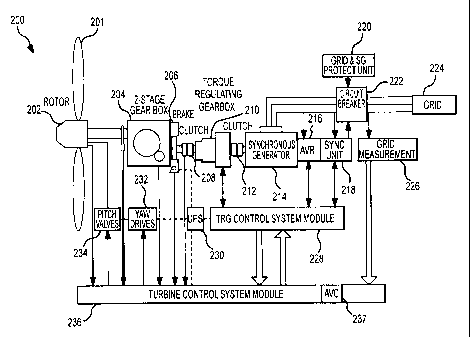
Figure 1 is a schematic diagram of one embodiment of an exemplary wind turbine
200 that may be
configured to provide adaptive voltage control and/or adaptive power factor
(PF) control. In operation, wind
imparts energy to the blades 201 of a wind rotor 202, which in tum imparts a
mechanical torque onto a shaft
of a synchronous generator 214. The synchronous generator 214 is coupled
directly to a power grid 224 to
1 5 provide power to customers using the power grid 224. To adjust and
control the rotational speed and torque
applied to the synchronous generator 214, a fixed 2-stage mechanical gearbox
204 and a torque-regulating
gearbox (TRG) 210 are disposed between the synchronous generator 214 and the
wind rotor 202. Further,
a turbine control system module 236 (which includes an Adaptive Voltage or PF
Controller (AVC) 237) and a
torque-regulating gearbox or TRG control system module 228 may be provided to
monitor and control the
various functions of the wind turbine 200. Each of the various components of
the wind turbine 200 is
described in greater detail below.
In one embodiment, the synchronous generator 214 is a 2 Megawatt (MW), 4 pole
self-excited
synchronous generator that operates at a constant frequency of 1800 RPM for 60
Hz power systems (1500
RPM for 50 Hz power systems), although other synchronous generators may be
utilized. An Automatic
Voltage Regulator (AVR) 216 may be coupled to the synchronous generator 214 to
provide voltage control,
power factor control, synchronization functions, and the like. Advantageously,
since the synchronous
generator 214 is directly connected to the power grid 224, the need for
complex power electronics to
condition or transform the power may be eliminated. As can be appreciated, any
suitable method may be
used for the excitation of the synchronous generator 214. In one embodiment,
the excitation system
includes a pilot exciter, which may include a permanent magnet generator
(PMG). Advantageously, this
configuration may eliminate the requirement of an outside power supply to
provide excitation, as well as
eliminating the need for slip rings and/or brushes, which may reduce the
maintenance requirements of the
synchronous generator 214.
As noted above, since the rotor speed of the synchronous generator 214 is
fixed to the frequency of
the power grid 224 and the wind speed is variable, the TRG 210 is provided to
convert the torque and speed
of the shaft of the wind rotor 202 to a form suitable for the synchronous
generator 214. The TRG 210 may
be of any appropriate configuration, for instance the TRG 210 may be in the
form of a superimposition
12
CA 02748459 2013-11-04
gearbox of any of a number of configurations. In one embodiment, the TRG 210
is a combination of a torque
converter and a planetary gear system. A representative configuration for the
TRG 210 is the WinDrive
available from Voith Turbo GmbH and Co. KG, having a place of business in
Heidenheim, Germany. One or
more features that may be used in relation to the TRG 210 are disclosed in
U.S. Patent Application
Publication Nos.: US 2005/0235636, entitled "Hydrodynamic Converter," and
published on October 27, 2005;
US 2005/0194787, entitled "Control System for a Wind Power Plant With
Hydrodynamic Gear," and published
on September 8, 2005; and US 2008/0197636, entitled "Variable-Speed
Transmission for a Power-Generating,"
and published on August 21, 2008.
The TRG 210 may be characterized as being disposed in a drive train that
extends between the
wind rotor 202 and the synchronous generator 214 (e.g., the drive train
transferring the rotation of the wind
rotor 202 to the synchronous generator 214). Any appropriate type of torque
regulator or torque-regulating
device/system may be utilized in place of the TRG 210 (in which case the above-
noted control module 228
may also be referred to as a "torque regulator control module 228"). The
torque regulator or torque-
regulating device/system may be incorporated in any appropriate manner in
relation to the drive train that
extends between the wind rotor 202 and the synchronous generator 214 (e.g., at
one or more locations).
Any appropriate way of regulating the torque transfer between the wind rotor
202 and the synchronous
generator 214 may be utilized (e.g., electrically, hydraulically).
In one embodiment shown in Figures 2A-2D, the TRG 210 includes a combination
of a hydraulic or
hydrodynamic torque converter 602, and a 2-stage functionally interconnected
revolving planetary gear
system 604 positioned between the 2-stage mechanical gearbox 204 and the
synchronous generator 214. In
the revolving planetary gear system 604, input power from an input shaft 606
(which is rotatably driven by
rotation of the wind rotor 202) is supplied to a carrier 608 of the left stage
of the revolving planetary gear
system 604. A plurality of planetary gears 610 are rotatably mounted on the
carrier 608. Any appropriate
number of planetary gears 610 may be utilized. Simultaneously, a hydrodynamic
circuit drives the outer
annulus (ring) gear 616 via a control drive. In most revolving planetary gear
systems, one of the three
elements (i.e., planet gear carrier, ring gear, or sun gear) is fixed. In the
TRG 210 however, all three
elements of the left stage of the planetary gear system 604 may rotate.
Between the annulus gear 616 and the
fluid-machine it may be necessary to adapt speed and direction of rotation by
means of a fixed gear
stage 614. The revolving planetary gear system 604 leads both power flows via
a sun gear 618 to an output
shaft 612 that connects to the synchronous generator 214. In the hydraulic
circuits, control power is taken from
the output shaft 612 with a pump wheel 620 of the hydrodynamic torque
converter 602 and returned to the
revolving planetary gear system 604 via a turbine wheel 622 of the
hydrodynamic torque converter 602. Power
flow in a variable speed gear unit can vary continuously by an interacting
combination of the revolving
planetary gear system 604 and the hydrodynamic torque converter 602.
The hydrodynamic torque converter 602 is provided with adjustable guide vanes
624 (incorporated by
a guide vane housing 626) and can thus be used as an actuator or control
variable for the power
13
CA 02748459 2011-06-28
WO 2010/085987
PCT/EP2009/003139
consumption of the pump wheel 620. The energy content of the fluid and torque
generated by the turbine
wheel 622 varies with changes in pump wheel 620 power consumption. Rotation of
the turbine wheel 622 is
at least in part dictated or otherwise controlled by the position of the guide
vanes 624. Figure 2C shows the
guide vanes 624 in the maximum open position (which would allow the turbine
wheel 622 to rotate at a
maximum speed under current conditions). Figure 2D shows the guide vanes 624
in the closed position.
Adjusting the position of the guide vanes 624 between the open position
(Figure 2C) and closed position
(Figure 2D) controls the rotational speed of the turbine wheel 622, as well as
the energy "absorbed" by the
hydrodynamic torque converter 602.
The heart of a hydrodynamic torque converter 602 is its hydraulic circuit;
including the pump wheel
620, turbine wheel 622, and a guide wheel or guide vane housing 626 with
adjustable guide vanes 624.
These components are combined in a common housing that contains hydraulic oil
or any other appropriate
fluid of an appropriate viscosity. The flow path of hydraulic fluid in the
common housing is shown
schematically in Figure 2B at the point indicated by the reference numeral
621. The mechanical energy of
the input shaft 606 is converted into hydraulic energy through the pump wheel
620. In the turbine wheel
622, the same hydraulic energy is converted back into mechanical energy and
transmitted to the output shaft
612. The adjustable guide vanes 624 of the guide wheel 626 regulate the mass
flow in the hydraulic circuit.
When the guide vanes 624 are closed (i.e., low mass flow; Figure 2D), the
power transmission is at its
minimum. When the guide vanes 624 are completely open (i.e., large mass flow;
Figure 2C), the power
transmission is at its maximum. Because of the change in mass flow (due to the
adjustable guide vanes
624), the speed of the turbine wheel 622 can be adjusted to match the various
operating points of the
synchronous generator 214.
In operation and referring now to both Figure 1 and Figures 2A-2D, the TRG
control system module
228 of the wind turbine 200 may control the positioning of the guide vanes 624
of the TRG 210 so that the
rotational speed and torque of the rotor shaft of the synchronous generator
214 is suitably controlled. That
is, the active power produced by the synchronous generator 214 may be
dynamically controlled. In this
regard, the TRG control system module 228 may communicate with the turbine
control system module 236
to achieve this function. The control system modules 228 and 236 may be
physically or logically isolated, or
may be combined into a single unit. Further, the control system modules 228
and 236 may be implemented
in hardware, software, a combination thereof, or in any appropriate manner. As
an example, the control
system modules 228 and 236 may be implemented in one or more "off-the-shelf or
customized
microcontrollers.
Although one example of the TRG 210 is described above, again it should be
appreciated that any
suitable configuration (e.g., any torque-regulating device (TRD)) may be
provided to convert the torque and
speed of the shaft of the wind rotor 202 to a form suitable for the
synchronous generator 214. As an
example, a TRD that includes electrical mechanisms (as opposed to hydraulic)
to regulate the torque and
speed of the shaft of the wind rotor 202 may be used.
14
CA 02748459 2011-06-28
WO 2010/085987 PCT/EP2009/003139
The wind turbine 200 of Figure 1 again includes a wind rotor 202 that in tum
includes a plurality of
rotor blades 201 (e.g., three rotor blades) that may be designed for optimum
aerodynamic flow and energy
transfer. Any appropriate number of rotor blades 201 may be utilized. Further,
the wind rotor 202 may
include a pitch control system that is operable to adjust the angle of the
rotor blades 201 in a
desired/required manner. To achieve this functionality, the wind rotor 202 may
include a hydraulic pitch
control system that includes pitch valves 234 that are controllable by the
turbine control system module 236.
The position or pitch of the rotor blades 201 could be simultaneously or
collectively adjusted, or could be
independently adjusted.
In addition to pitch control, the wind turbine 200 of Figure 1 may also
include controllable yaw
drives 232 that are operable to adjust the direction that the wind turbine 200
faces (specifically the direction
that the wind rotor 202 faces). For example, the turbine control system module
236 may control the yaw
drives 232 to rotate the wind rotor 202 and its rotor blades 201 to face into
the direction of the wind, such
that the efficiency of the wind turbine 200 may be optimized.
The wind turbine 200 may also include an uninterruptable power supply (UPS)
230. The UPS 230
1 5 may be coupled to various components (e.g., the pitch valves 234, the
control system modules 228 and 236,
and the like) and functions to provide power to the components, especially
when a main source of power is
not available. The UPS 230 may include any type of power system, including one
or more batteries,
photovoltaic cells, capacitors, flywheels, and the like.
The wind turbine 200 may also include a controllable mechanical brake 206
coupled between the 2-
stage gearbox 204 and the TRG 210. The brake 206 may be controlled by the
turbine control system
module 236 to reduce the rotational speed of the wind rotor 202. It should be
appreciate that any suitable
braking mechanism may be used, including but not limited to tip brakes,
ailerons, spoilers, boundary layer
devices, and the like. One or more brakes of any appropriate type may be
included in the drive train
between the wind rotor 202 and the synchronous generator 214, for instance so
as to be disposed between
the wind rotor 202 and the TRG 210. In addition, friction clutches 208 and 212
may be disposed in the
mechanical drive train to limit the torque applied between components and to
selectively couple and
decouple the various shafts of the drive train components.
As can be appreciated, before the synchronous generator 214 is coupled
directly to the power grid
224, certain conditions must be met. For example, the stator voltage of the
synchronous generator 214
must substantially match the voltage of the power grid 224, and the frequency
and phase of the voltages
must match as well. To achieve this functionality, a synchronization unit 218,
a grid measurement unit 226,
and a circuit breaker 222 may be provided for the wind turbine 200. In
operation, the synchronization unit
218 may communicate with the AVR 216 and the control system modules 236 and
228 to adjust the voltage
characteristics of the synchronous generator 214 to match those of the power
grid 224 as measured by the
grid measurement unit 226. Once the voltage characteristics substantially
match on both the generator side
and the power grid side, the synchronization unit 218 may send a command to
the circuit breaker 220 to
close the circuit, thereby coupling the synchronous generator 214 to the power
grid 224. The circuit breaker
CA 02748459 2011-06-28
WO 2010/085987 PCT/EP2009/003139
222 may also be coupled to a grid and generator protection unit 220 that is
operative to sense harmful
conditions where it may be desirable to disconnect the wind turbine 200 from
the power grid 224.
As noted above, the turbine control system module 236 includes the AVC 237
that may be
configured to adaptively control the output voltage, PF, and active power
delivery of the synchronous
generator 214 in response to detecting at least certain grid conditions. The
specific details of embodiments
of the AVC 237 are described below with reference to Figures 4 and 5. Although
the AVC 237 may be
described in relation to the configuration of the wind turbine 200, it may be
utilized by various other wind
turbine designs that utilize a synchronous generator.
Figure 3 illustrates a graph 250 of grid voltage (dark line) versus time for a
weak grid. As shown,
the axis 254 represents the grid voltage expressed as a percentage of the
rated grid voltage. The axis 252
represents time, with each label along the axis 252 being separated by twelve
hours. From the graph 250 it
can be seen that the grid voltage fluctuates from about 101% to 104% of the
rated grid voltage throughout
each day due to variable consumer loads and/or a weak grid. In certain
conditions, it may be desirable to
utilize wind turbine generators to control the voltage on a power grid by
supplying or consuming reactive
power. However, it has been observed that for weak grids, it may not be
possible for individual wind turbine
generators to reduce the voltage of the power grid during times of light
consumer loads. As a result, the
wind turbine generators may consume the maximum possible amount of reactive
power for long periods of
time in an effort to reduce the grid voltage. This extended reactive power
consumption by the wind turbine
may decrease the efficiency of the wind turbine generator, as well as impair
the delivery of active power.
To remedy this problem, the adaptive voltage controller (AVC) 237 may be
configured to determine
or recognize conditions when the grid voltage is above the rated voltage due
to a certain condition (e.g.,
fluctuations due to variable consumer loads), and in response to identifying
such a condition, to minimize the
reactive power consumed by the synchronous generator 214. In this regard, the
synchronous generator 214
may not act to reduce the grid voltage unless the grid voltage has reached an
unacceptable level (e.g., at
least 105% of the rated grid voltage) or if the grid voltage is above the
rated grid voltage due to conditions
other than the conditions that are to be "ignored" by the AVC 237 (e.g.,
periodic fluctuations in the grid
voltage).
Figure 4 illustrates a functional block diagram 300 that may be used by the
adaptive voltage
controller or AVC 237 shown in Figure 1. Generally, the AVC 237 in this
configuration is operative to provide
an adapted voltage reference to the AVR 216, which in tum modifies the
excitation current ie in the rotor
winding of the synchronous generator 214 to regulate the voltage of the
synchronous generator 214. The
effect of the adapted voltage reference is generally to cause the AVR 216 to
ignore voltage fluctuations in
the power grid 224 that are due to the normal hourly, daily, seasonal, yearly,
or other fluctuations caused by
variable consumer loads on a weak grid. Initially, the AVC 237 receives a
measured reactive power signal
Qmeasured (e.g., from the grid measurement unit 226, from the AVR 216, or the
like). The measured reactive
power Qmeasured is then filtered by a low pass filter 302 to generate a QFIL
signal. The low pass filter 302
generally operates to remove any high frequency fluctuations in the measured
reactive power Qmeasured=
16
CA 02748459 2011-06-28
WO 2010/085987 PCT/EP2009/003139
Once the measured reactive power Qmeasured has been filtered, a nominal
reactive power reference QREF is
then subtracted from QFIL by a subtractor 304, which generates a reactive
power error signal that is fed into
a Proportional-Integral (PI) controller 306. The nominal reactive power
reference QREF may be any value,
including zero VARS, depending on the desired operation for the wind turbine
200.
In operation, the PI controller 306 provides an output VREF1 that is dependent
upon characteristics
of the difference between Qmeasured and QREF (i.e., Qem). More specifically,
VREF1 is related to the weighted
sum of the reactive power error signal Qeffor and the integral of the reactive
power error signal Qmor. So that
the PI controller 306 may suitably adjust the reference voltage supplied to
the AVR 216, the PI controller 306
may have a time constant that is relatively large (e.g., several seconds,
several minutes, several hours, or
more). In this regard, the voltage reference will only be adapted when the
weighted sum of the reactive
power error signal %re:, is large (e.g., more than 1 kilowatt, more than 100
kilowatts, or the like) and/or has
persisted for a period of time (e.g., several minutes, several hours, or the
like) such that hourly, daily,
weekly, or other periodic grid fluctuations may be ignored.
To constrain the output of the PI controller 306, the VREF1 signal may be fed
into a limiter 308 that is
operative to limit VREF1 to within VADAPT,MIN and VADAPT,MAX. As an example,
VADAPT,MAX and VADAPT,MIN may be
+3% and ¨3% of the rated grid voltage, respectively, or whatever suitable
limits for the adapted reference
voltage that may be desirable. Each of VADAPT,MAX and VADAPT,MIN may be of any
appropriate value.
After the limiter 308, a nominal voltage reference signal VREF,NOM may be
added to the limited
voltage reference signal VREF2 by the adder 310 to generate a VREFADAK signal.
The VREF,Nom signal may be
100% of the rated voltage, for example. The VREF,ADAPT signal may then be
provided to the AVR 216, which
may in turn control the excitation current ie of the synchronous generator 214
to maintain the voltage at the
stator of the synchronous generator 214 at VREF,ADAPT. To achieve this, the
AVR 216 may feed an error
signal from a subtractor 312 into a PI controller 314, which may then output
an excitation current ie to the
rotor winding of the synchronous generator 214.
Figure 5 illustrates a block diagram of one embodiment of adaptive voltage/PF
controller 400 with
active power derating and that may be used by the AVC 237. Generally, the
controller 400 may be operable
to permit the wind turbine 200 to increase the reactive power consumed to a
level that is above the
maximum reactive power that can be consumed when the synchronous generator 214
is operating at rated
power (e.g., 2 MW). This feature is achieved by derating the active power
delivery of the synchronous
generator 214 when necessary. That is, the inherent properties of the
synchronous generator 214 may be
used to permit the synchronous generator 214 to consume additional reactive
power under certain
conditions by reducing the active power delivery (e.g., from 2MW to 1.7 MW).
This functionality may be
desirable when synchronous generators are coupled to weak grids, which may
have tendencies for voltage
levels to rise above rated levels under light consumer load conditions. A
discussion of the relationship
between active power and reactive power capabilities of the synchronous
generator 214 is presented below
with reference to Figure 6.
17
CA 02748459 2011-06-28
WO 2010/085987
PCT/EP2009/003139
The first portion of the controller 400 is a Voltage Control Mode (VCM)
adaptive controller 402 that
is operable to generate a derated active power reference PCORR,V2 when the
voltage Vmeasured of the
synchronous generator 214 rises above a threshold voltage VREF,MAX (e.g.,
above 103% of rated voltage). To
achieve this functionality, the measured voltage Vmeasured of the synchronous
generator 214 is first subtracted
from VREF,MAX by a subtractor 406 to generate an error signal. Then, this
error signal is fed into an integrator
408, which is operable to generate a first corrected active power reference
PcoRRvi. As an example,
PCORR,V1 may be number between 0 and 1, such that when multiplied by the rated
active power for the
synchronous generator 214, a value that is between 0% and 100% of the rated
active power is generated
(e.g., 0.8 x 2MW = 1.6 MW). To constrain the possible values for the first
corrected active power reference,
a limiter 410 may be provided that is operative to limit PCORRvi to a value
that is within PCORR,MIN and
PCORR,MAX (e.g., between 0.5 and 1.0), thereby generating a second corrected
active power reference
PCORR,V2 for the VCM adaptive controller 402. Each of PCORRMIN and PCORR,MAX
may be of any appropriate
value.
The second portion of the controller 400 is a Power Factor Control Mode (PFCM)
adaptive
1 5 controller 404 that is operable to generate a derated active power
reference PcompF2 when the power factor
(PF) reference setting is such that the synchronous generator 214 cannot
operate at that PF while
generating the rated active power (see Figure 6). To achieve this
functionality, the controller 404 first
receives a PFREF signal, for example, from a utility or grid operator. The
PFREF signal may be fed to a limiter
412 to constrain the possible PF reference values to within PFmiN and PF mAx
(e.g., between 0.6 - 1.0 PF).
Each of PFmiN and PF wtx may be of any appropriate value. The resulting signal
may then be fed to a PQ
Capability Table 414 that is operative to receive a PF reference signal, and
to generate a first corrected
active power reference PCORR,PF1 that is dependent upon the specific
capabilities of the synchronous
generator 214. As an example, the PQ Capability Table 414 may include a lookup
table that includes
capability data for the synchronous generator 214. To constrain the values for
the first corrected active
power reference PCORR,PF1, a limiter 416 may be provided that is operative to
limit PCORR,PF1 to a value that is
between PCORR,MIN and PcoRRmAx (e.g., between 0.6 and 1.0 of rated active
power), thereby generating
PCORR,PF2 for the PF Control mode adaptive controller 404. Each of PCORR,MIN
and PCORR,MAX may be of any
appropriate value.
In the embodiment shown in Figure 5, the output signals PCORR,V2 and PCORRPF2
are each fed into a
module 418 that is operable to compare the two inputs, and to output the
minimum of the two, PcORN to the
turbine control system (TCS) module 236. In this regard the active power of
the synchronous generator 214
may then be derated by at least an amount that is required by the Voltage
Control mode module 402 and the
PF control mode module 404. In operation, the TCS module 236 may utilize the
PcoRR reference to modify
the active power delivery of the synchronous generator 214 to achieve the
desired voltage or PF
characteristics.
To implement the active power derating functionality, the turbine control
system module 236 may
interact with the TRG control system module 228 to adjust to the speed-torque
characteristics of the TRG
18
CA 02748459 2011-06-28
WO 2010/085987 PCT/EP2009/003139
210. That is, the control system modules 228 and 236 may selectively adjust
the position of the guide vanes
624 of the TRG 210 such that the active power delivery of the synchronous
generator 214 is reduced from
the rated active power dependent on the adapted active power reference PcoRR.
Figure 6 illustrates an active and reactive power capability curve (PQ
capability curve) 500 for a
synchronous generator, such as the synchronous generator 214 shown in Figure
1. Generally, the ability of
a synchronous generator to provide reactive power support is dependent upon
its active power production.
The generator's prime mover (e.g., a wind turbine rotor) may be designed with
less capacity than the
generator itself, resulting in the "Wind Turbine Drive Train Power Limit"
shown in Figure 6. Further, the
current carrying capability of the armature (stator) of the generator results
in the "Stator Heating Limit."
Additionally, production of reactive power involves increasing the magnetic
field to raise the generator's
terminal voltage, which in turn requires increasing the current in the rotor
field winding. The current
capability of the rotor field winding results in the "Field Heating Limit."
Conversely, absorption of a large
amount of reactive power leads to an "Under Excitation Limit," which is
determined by both system stability
limits and also heating limits in the stator winding when significant reactive
power is drawn from a power
grid.
The point 502 in Figure 6 indicates the maximum amount of reactive power that
can be absorbed
by the synchronous generator 214 while the generator is operating at rated
active power (e.g., 2 MW). In
this example, this condition occurs when the synchronous generator 214 is
operating at a power factor of 0.9
leading. The point 504 illustrates that, in order for the synchronous
generator 214 to absorb additional
reactive power, the active power must be derated to a level that is below the
Wind Turbine Drive Train
Power Limit (i.e., rated power). That is, in order for the generator to
operate at a PF that is less than 0.9, the
active power may be derated using, for example, the controller 400 shown in
Figure 5.
Figure 7 is an operations protocol 700 of one embodiment of an adaptive
voltage control scheme
for a wind turbine (WT), including the wind turbine 200 shown in Figure 1. The
wind turbine may include a
synchronous generator that is coupled directly to a power grid (see e.g., the
synchronous generator 214 of
the wind turbine 200 shown in Figure 1). In operation, the operations protocol
700 may include maintaining
an electrical connection between the synchronous generator (SG) and the power
grid (step 702). For
example, stator terminals of the synchronous generator may be directly coupled
to the power grid.
The operations protocol 700 may also include operating the wind turbine
according to a nominal
control scheme (step 704). For example, the nominal control scheme may include
an automatic voltage
regulator (AVR) that is configured to measure a voltage of the power grid, and
to control the voltage of the
power grid by selectively adjusting an amount of reactive power supplied or
absorbed by the synchronous
generator. In this regard, the AVR may be configured to receive a voltage
reference, and to cause the
voltage of the power grid to track the voltage reference using any suitable
control scheme (e.g., PI control).
To account for a predefined condition of the power grid, such as voltage
fluctuations due to varying
consumer loads on a weak grid, the operations protocol 700 may include
monitoring the power grid for the
19
CA 02748459 2011-06-28
WO 2010/085987 PCT/EP2009/003139
occurrence of the predefined condition (step 706). As an example, the
monitoring step 706 may include
measuring and analyzing a reactive power characteristic of the synchronous
generator.
The operations protocol 700 may also include determining whether the
predefined condition exists
(step 708). As can be appreciated, if the predefined condition is not detected
by the monitoring step 706,
then the operations protocol 700 may continue to operate the WT using the
nominal control scheme.
However, if the operations protocol 700 determines that the predefined
condition is present, the operations
protocol 700 may modify the nominal control scheme dependent upon a
characteristic of the predefined
condition (step 712).
As an example, the nominal control scheme may be modified dependent on a
magnitude and/or an
integral of a magnitude of a reactive power characteristic (e.g., reactive
power absorbed or delivered) of the
synchronous generator. Further, continuing with the example above, the nominal
control scheme may be
modified by providing a modified (or adapted) voltage reference to the nominal
control scheme to provide a
modified control scheme. Finally, the wind turbine may be operated using the
modified control scheme (step
710) so long as the predefined condition exists.
Figure 8 illustrates a monitoring protocol 800 that may be used, for example,
in an operations
protocol such as the operations protocol 700 shown in Figure 7. Initially, the
monitoring protocol 800 may
measure a characteristic of the synchronous generator for a period of time
(step 802). For example, a
reactive power characteristic, a voltage characteristic, a current
characteristic, or any other suitable
characteristic may be measured. The next step in the monitoring protocol is to
analyze the measured
characteristic of the synchronous generator (step 804). As an example, the
analyzing step 804 may include
performing one or more mathematical operations on the measured characteristic
(e.g., PI control, or the
like). Once the measured characteristic has been analyzed, the monitoring
protocol 806 may determine the
presence or absence of the predefined condition on the power grid.
In one embodiment, a reactive power characteristic is measured during step
802, and the
measured reactive power characteristic is fed to PI control logic during the
analyzing step 804. In this
regard, the PI control logic may be operative to analyze the measured reactive
power characteristic, and to
determine the presence or absence of the predefined condition (e.g., voltage
fluctuations due to a weak
grid). As an example, the PI control logic may determine that a voltage
characteristic of the power grid is
due to a weak grid because the synchronous generator is absorbing a relatively
large amount of reactive
power for a relatively long period of time, thereby indicating that the
voltage of the power grid is above a
rated voltage.
Figure 9 illustrates an adaptive control protocol 900 that may be used, for
example, in an
operations protocol such as the operations protocol 700 shown in Figure 7.
Initially, the wind turbine (WT)
may be operated using a nominal control scheme (step 902). As discussed above,
the nominal control
scheme may include an automatic voltage regulator (AVR) that is configured to
measure a voltage of the
power grid, and to control the voltage of the power grid by selectively
adjusting an amount of reactive power
supplied or absorbed by the synchronous generator. In this regard, AVR may be
configured to receive a
CA 02748459 2011-06-28
WO 2010/085987 PCT/EP2009/003139
control variable (e.g., a voltage reference), and to cause the voltage of the
power grid to track the voltage
reference using any suitable control scheme (e.g., PI control).
Next, if the monitoring protocol 800 (see Figure 8) determines that the
predefined condition is
present, the adaptive control protocol 900 may generate a control variable
that is dependent on a
characteristic of the predefined condition (step 904). For example, in the
case where the predefined
condition is determined using a reactive power characteristic, the control
variable may be dependent upon
one or more features of the reactive power characteristic (e.g., a magnitude
and/or an integral of the
magnitude of the reactive power characteristic).
The control variable may then be provided to the nominal control scheme (step
906), which may
have the effect of modifying the nominal control scheme dependent upon the
control variable (step 908).
For example, a modified (or adapted) voltage reference may be provided to the
nominal control scheme to
generate the modified control scheme. Finally, the wind turbine may be
operated according to the modified
control scheme using the control variable that is dependent upon a
characteristic of the predefined condition
(step 910).
Figure 10 illustrates an operations protocol 1000 for one embodiment of an
active power delivery
control scheme for a wind turbine (WT). As in previously described
embodiments, the wind turbine may
include a synchronous generator that is coupled directly to a power grid (see
e.g., the wind turbine 200
shown in Figure 1). In operation, the operations protocol 1000 may include
maintaining an electrical
connection between the synchronous generator (SG) and the power grid (step
1002). For example, stator
terminals of the synchronous generator may be directly coupled to the power
grid.
The operations protocol 1000 may also include operating the wind turbine in a
first active power
control mode (step 1004). For example, the first active power control mode may
include operating the
synchronous generator of the wind turbine at a level that is substantially
equal to a rated active power level.
The operations protocol 1000 may also include monitoring for a predefined
condition (step 1006), and
determining whether the predefined condition exists (step 1008). The two steps
1006 and 1008 are
described in further detail below with reference to Figure 11.
If it is determined that the predefined condition exists, the operations
protocol 1000 may then
operate the wind turbine in a second active power control mode (step 1010).
Further, the second active
power control mode may include operating the synchronous generator at an
active power level that is less
than the rated active power level (e.g., 80% of the rated active power level).
As noted above in the discussion associated with Figure 5, in certain
circumstances it may be
desirable to operate the synchronous generator at an active power level that
is below the rated active power
level (i.e., active power derating). For example, the physical characteristics
of the synchronous generator
may dictate that the active power should be reduced in circumstances where it
is desirable for the
synchronous generator to consume a relatively large amount of reactive power.
Figure 11 illustrates a protocol 1100 for monitoring for a predefined
condition, and for determining
whether the predefined condition is present. Initially, the protocol 1100 may
be operative to measure or
21
CA 02748459 2011-06-28
WO 2010/085987 PCT/EP2009/003139
receive a parameter (step 1102). Next, the protocol 1100 may be operative to
analyze the parameter
dependent upon a characteristic of the synchronous generator of the wind
turbine (step 1104). Further, the
protocol 1100 may include determining the presence or absence of the
predefined condition (step 1106), so
that the wind turbine may be operated accordingly in either the first active
power control mode or the second
active power control mode. As can be appreciated, the predefined condition may
include any suitable
condition where it may be desirable to operate a wind turbine in either a
first or second active power control
mode dependent upon the condition.
For example, the step 1102 may be operative to receive a power factor
reference as the parameter
(e.g., from a grid or utility operator). In this example, the steps 1104 and
1106 may compare the power
factor reference with the operational characteristics (e.g., PQ capability
curve) of the synchronous generator,
and if necessary, operate to reduce the active power level of the synchronous
generator so that it may
operate at the power factor specified by the power factor reference. To
achieve this, the power factor
reference may be compared to a lookup table that includes the PQ capability
characteristics of the
synchronous generator.
In another example, the protocol 1100 may include logic that is operative to
measure a voltage of
the power grid, and to reduce the active power level of the synchronous
generator when it is desirable to
increase the reactive power absorbed by the synchronous generator above a
maximum amount that is
possible when operating at a rated active power level (see Figure 5 and
related discussion). This condition
may occur, for example, when the voltage of the power grid is too high even
when the synchronous
generator is absorbing the maximum reactive power possible when operating at
rated active power, such
that it is desirable for the synchronous generator to absorb additional
reactive power to attempt to lower the
voltage of the power grid.
Figure 12 illustrates a protocol 1200 for transitioning a wind turbine between
a first active power
control mode to a second active power control mode. Initially, the wind
turbine may be operated in a first
active power control mode (step 1202). Then, an active power reference may be
generated dependent on a
characteristic of the synchronous generator, (step 1204). For example, the
active power reference may be
generated dependent upon the operational characteristics of the synchronous
generator (e.g., PQ capability
curve) and a measured or received parameter (see step 1102 of Figure 11).
Once the active power reference has been generated, it may then be provided to
control logic used
to operate the wind turbine (step 1206). The control logic in turn may be
operative to operate the wind
turbine in a second active power control mode using the active power reference
(step 1208). For example,
the control logic may be operative to control various components of the wind
turbine, such as the
synchronous generator, the rotor blades, or a torque-regulating gearbox (e.g.,
the TRG 210 shown in
Figures 1-3), to operate the wind turbine in the first and second active power
control modes.
Figure 13 illustrates an operations protocol 1300 of another embodiment of an
adaptive control
scheme for a wind turbine (WT). The wind turbine may include a synchronous
generator that is coupled
directly to a power grid (see e.g., the wind turbine 200 shown in Figure 1).
In operation, the operations
22
CA 02748459 2013-11-04
protocol 1300 may include maintaining an electrical connection between the
synchronous generator (SG) and
the power grid (step 1302). For example, stator terminals of the synchronous
generator may be directly
coupled to the power grid.
The operations protocol 1300 may also include providing a reference to a
control scheme that is
used to operate the wind turbine (step 1304). As an example, the control
scheme may be operative to
selectively control a voltage of the power grid using the reference. The
operations protocol 1300 may then
operate the wind turbine according to the control scheme using the reference
(step 1306).
The operations protocol 1300 may further be operative to monitor a
characteristic of the power grid
(step 1308), and to adapt the reference dependent upon the monitored
characteristic of the power grid (step
1310). As an example, the monitoring may include measuring a reactive power
characteristic over a period
of time, and analyzing it (e.g., using PI control logic) to determine a
characteristic of the power grid, such as the
presence of voltage fluctuations caused by varying consumer loads on a weak
grid. Then, the operations
protocol 1300 may be operative to continuously adapt the reference provided to
the control scheme such
that, for example, the characteristic of the voltage grid may be compensated.
In one example, the control scheme includes an AVR that is configured to
selectively control the
voltage of the power grid to track a reference voltage by adjusting the
reactive power absorbed or supplied by
the synchronous generator. In this example, the voltage reference may be
adapted such that conditions
caused by a weak grid may substantially be "ignored" by the adapted control
scheme. That is, if the
monitoring step 1308 determines that the voltage of the power grid is higher
than a rated voltage due to the
weak grid, the reference voltage of the AVR may be adaptively increased, so
that the synchronous generator is
not controlled to absorb a relatively large amount of reactive power for a
relatively long period of time, which
may diminish the performance of the synchronous generator.
While the invention has been illustrated and described in detail in the
drawings and foregoing
description, such illustration and description is to be considered as
exemplary and not restrictive in
character. For example, certain embodiments described hereinabove may be
combinable with other
described embodiments and/or arranged in other ways (e.g., process elements
may be performed in other
sequences).
23