Note: Descriptions are shown in the official language in which they were submitted.
CA 02748731 2016-07-08
1
An arrangement and a method for controlling a measurement head of an op-
tical measurement instrument
Field of the invention
The invention relates to an arrangement and a method for controlling a measure-
ment head of an optical measurement instrument. An optical measurement can
be, for example but not necessarily, an absorption measurement, a photolumines-
cence measurement, or a chemiluminescence measurement. Furthermore, the in-
vention relates to an optical measurement instrument.
Background
The work in analytical biochemical laboratories and in clinical laboratories
is often
based on different tags or labels coupled on macromolecules under inspection.
Typical labels used are different radioactive isotopes, enzymes, different
fluores-
cent molecules and e.g. fluorescent chelates of rare earth metals. Detection
of en-
zyme labels can be performed by utilizing its natural biochemical function,
i.e. to
alter the physical properties of molecules. In enzyme immunoassays colourless
substances are catalysed by enzyme to colourful substances or non-fluorescent
substances to fluorescent substances.
The colourful substances can be measured with absorption measurement, i.e.
photometric measurement. In the absorption measurement the intensity of
filtered
and stabilized beam is first measured without any sample and then the sample
in-
side one plate is measured. The absorbance i.e. the absorption values are then
calculated.
The fluorescent substances can be measured with fluorescent measurement that
is generally used for measuring quantities of fluorescent label substance in a
sam-
ple. The most photoluminescence labels are based on molecular photolumines-
cence process. In this process optical radiation is absorbed by the ground
state of
a molecule. Due to the absorption of energy the quantum molecule rises into
high-
er excited state. After the fast vibrational relaxation the molecule returns
back to its
ground state and the excess energy is released as an optical quantum. Due to
losses in this process the average absorbed energies are higher than the
average
emitted energies.
CA 02748731 2016-07-08
. .
2
A further measurement method is chemiluminescence measurement where emis-
sion of a substance is measured from a sample without excitation by
illumination.
Thus a photoluminometer suitable for photoluminescence measurements can also
be used as a chemiluminometer.
Further, there is an analysing method called Amplified Luminescent Proximity
Ho-
mogeneous Assay or AlphaScreenTM. The function of the AlphaScreenTM method
is based on the use of small beads that attach to the molecules under study.
There
are two types of beads that are coated with a material acting either as a
donor or
acceptor of singlet-state oxygen. The measurement starts, when the liquid
sample
is illuminated by light with a suitable wavelength e.g. 680 nm. After this,
the mate-
rial in the donor bead converts ambient oxygen into singlet-state oxygen. The
sin-
gle-state molecules have a short lifetime and they can reach only about a 200
nm
distance by diffusion in the liquid. If the chemical reaction in question has
taken
place, both the donor and acceptor beads are bound to the same molecule and so
they are sufficiently close to each other. In this case the singlet-state
oxygen may
reach the acceptor bead where a series of reactions is started. As the last
phase
of the reaction the coating material in the acceptor beads emits photons in
the
500-700 nm range. If the chemical reaction has not taken place the singlet-
state
oxygen cannot reach the acceptor bead and the emission light is not detected.
By
measuring the intensity of light it is possible to conclude the efficiency of
the chem-
ical reaction.
An optical measurement instrument suitable for performing some or all of the
measurements of the kind described above comprises typically at least one
excita-
tion light source for producing excitation beams to one or more samples to be
measured at each time. Each excitation light source can be for example a flash
lamp or a laser source. An optical path from an excitation light source to a
sample
may contain for example lenses, fibers, mirrors, dichroic mirrors, optical
filters,
monochromators and/or other optical elements. The optical measurement instru-
ment further comprises at least one detector for detecting emission beams
emitted
by the samples to be measured at each time, and for producing detection
signals
responsive to the detected emission beams. Each detector can be for example a
photodiode or a photomultiplier tube. An optical path from the sample to the
detec-
tor may contain for example lenses, fibers, mirrors, dichroic mirrors, optical
filters,
monochromators, and/or other optical elements. The optical measurement instru-
ment may further comprise a processing device for producing a measurement re-
sult for each sample to be measured on the basis of the detection signal
related to
CA 02748731 2016-07-08
=
3
that sample. Each sample to be measured is stored in one of a plurality of
sample
wells that are built on a sample plate, e.g. a microtitration plate. The
optical meas-
urement instrument may comprise, for example, a movable sledge adapted to re-
ceive the sample plate. Due to the fact that the sample plate is movable, the
sam-
ples can be measured in a temporally successive manner so that each sample is
in turn the sample that is currently being measured and/or excited. In this
docu-
ment an optical module or element that is arranged to direct an excitation
beam to
a sample and/or to collect emission beam from a sample is called a measurement
head. In other words, the measurement head is an optical interface of the
optical
measurement instrument with respect to a sample to be measured and/or excited.
In order to provide appropriate optical measurements, the distance from the
measurement head to a sample to be measured and/or excited has to be adjusted
with a sufficient accuracy. For example in conjunction with many optical
measure-
ments, an excitation beam has to be appropriately focused to the sample. The
dis-
tance between the measurement head and the sample can be adjusted to a de-
sired value for example by first moving the measurement head towards the
sample
plate and, after the measurement head has touched the sample plate, by moving
the measurement head backwards away from the sample plate with a pre-
determined length of movement so as to provide the desired distance between
the
measurement head and the sample plate. The situation in which the measurement
head touches the sample plate can be detected, for example, with a force
sensor
attached to the measurement head and arranged detect force directed by the
measurement head to the sample plate. An inconvenience related to a technical
solution of the kind described above is that the measurement head can be a
changeable module in which case each measurement head has to be provided
with an own force sensor or, alternatively, the force sensor has to be moved
from
one measurement head to another measurement head every time when the
measurement head is changed.
Summary
In accordance with a first aspect of the invention, there is provided a new ar-
rangement for controlling a measurement head of an optical measurement instru-
ment, the measurement head being an optical interface of the optical measure-
ment instrument with respect to a sample to be measured and/or excited, and
the
optical measurement instrument further comprising first mechanical support ele-
ments arranged to support a sample plate to be received and second mechanical
support elements arranged to support the measurement head and to allow a dis-
CA 02748731 2016-07-08
4
tance from the measurement head to the sample plate to be changed. The ar-
rangement according to the invention comprises:
- a controller arranged make the second mechanical support elements to
move the measurement head towards the sample plate and, as a response
to a situation in which the measurement head touches the sample plate, to
move the measurement head backwards away from the sample plate with a
pre-determined length of movement so as to provide a pre-determined dis-
tance between the measurement head and the sample plate, and
- a sensor device arranged to detect the situation in which the
measurement
head touches the sample plate,
wherein the sensor device is attached to the first mechanical support elements
and arranged to detect a mechanical effect occurring in the first mechanical
sup-
port elements due to force directed by the measurement head to the sample
plate
when the measurement head touches the sample plate.
The situation in which the measurement head touches the sample plate can be de-
tected without a need to provide the measurement head with a sensor. This is
ad-
vantageous because the measurement head can be a changeable module of the
optical measurement instrument and thus, using the arrangement according to
the
invention, there is no need to provide each measurement head with an own
sensor
or to move a force sensor from one measurement head to another measurement
head every time when the measurement head is changed.
In accordance with a second aspect of the invention, there is provided a new
opti-
cal measurement instrument comprising:
- a measurement head being an optical interface of the optical measurement
instrument with respect to a sample to be measured and/or excited,
- first mechanical support elements arranged to support a sample plate to
be
received,
- second mechanical support elements arranged to support the measurement
head and to allow a distance from the measurement head to the sample
plate to be changed,
- a controller arranged make the second mechanical support elements to
move the measurement head towards the sample plate and, as a response
CA 02748731 2016-07-08
_
to a situation in which the measurement head touches the sample plate, to
move the measurement head backwards away from the sample plate with a
pre-determined length of movement so as to provide a pre-determined dis-
tance between the measurement head and the sample plate, and
5 - a
sensor device arranged to detect the situation in which the measurement
head touches the sample plate,
wherein the sensor device is attached to the first mechanical support elements
and arranged to detect a mechanical effect occurring in the first mechanical
sup-
port elements due to force directed by the measurement head to the sample
plate.
In accordance with a third aspect of the invention, there is provided a new
method
for controlling a measurement head of an optical measurement instrument, the
measurement head being an optical interface of the optical measurement instru-
ment with respect to a sample to be measured and/or excited, and the optical
measurement instrument further comprising first mechanical support elements ar-
ranged to support a sample plate to be received, and second mechanical support
elements arranged to support the measurement head and to allow a distance from
the measurement head to the sample plate to be changed. The method according
to the invention comprises:
- moving the measurement head towards the sample plate,
- detecting, from the first mechanical support elements, a mechanical effect
occurring in the first mechanical support elements in order to detect a situa-
tion in which the measurement head touches the sample plate, and
-
as a response to the situation in which the measurement head touches the
sample plate, moving the measurement head backwards away from the
sample plate with a pre-determined length of movement so as to provide a
pre-determined distance between the measurement head and the sample
plate.
A number of exemplifying embodiments of the invention are described in accom-
panied dependent claims.
Various exemplifying embodiments of the invention both as to constructions and
to
methods of operation, together with additional objects and advantages thereof,
will
CA 02748731 2016-07-08
6
be best understood from the following description of specific exemplifying
embod-
iments when read in connection with the accompanying drawings.
The verb "to comprise" is used in this document as an open limitation that
does not
exclude the existence of also unrecited features. The features recited in
depending
claims are mutually freely combinable unless otherwise explicitly stated.
Brief description of the figures
The exemplifying embodiments of the invention and their advantages are ex-
plained in greater detail below in the sense of examples and with reference to
the
accompanying drawings, in which:
figure la shows a schematic illustration of an optical measurement instrument
comprising an arrangement according to an embodiment of the invention for con-
trolling a measurement head of the optical measurement instrument,
figure lb shows a schematic illustration of a view seen downwards from line A-
A of
figure 1 a,
figure 2 shows a schematic illustration of an optical measurement instrument
com-
prising an arrangement according to an embodiment of the invention for
controlling
a measurement head of the optical measurement instrument, and
figure 3 shows a flow chart of a method according to an embodiment of the
inven-
tion for controlling a measurement head of an optical measurement instrument.
Description of the embodiments
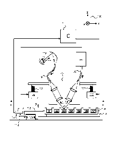
Figure la shows a schematic illustration of an optical measurement instrument
comprising an arrangement according to an embodiment of the invention for con-
trolling a measurement head of the optical measurement instrument. Figure 1 b
shows schematic illustration of a view seen downwards from line A-A of figure
la.
The optical measurement instrument comprises first mechanical support elements
arranged to support a sample plate 106, e.g. a microtitration plate. Samples
151,
152, 153, 154, 155, 156, 157 to be measured are stored in sample wells that
are
built on the sample plate 106. The first mechanical support elements comprise
a
support rail 103 and guide elements 104 and 105 shown in figure lb. The
support
rail 103 is supported relative to a body of the optical measurement instrument
with
the aid of the guide elements 104 and 105 in such a manner that the support
rail is
movable in the directions of a two-headed arrow 115 shown in figure 1 b. The
first
CA 02748731 2016-07-08
_
7
mechanical support elements comprise a sledge 114 capable of receiving the
sample plate 106. The sledge is connected with the aid of a part 102 of the
first
mechanical support elements to the support rail 103 in such a manner that the
sledge is capable of sliding along the support rail in the longitudinal
direction of the
support rail, i.e. the sledge is movable in the directions of a two-headed
arrow 116
shown in figure lb. Hence, the samples stored in the sample wells of the
sample
plate 106 are movable in the xy-plane defined by a co-ordinate system 190. Due
to
the fact that the samples are movable in the xy-plane, the samples can be meas-
ured in a temporally successive manner so that each sample is in turn the
sample
that is currently being measured.
The optical measurement instrument comprises an excitation light source 118
that
can be for example a flash lamp such as a xenon flash lamp. The excitation
light
produced by the excitation light source is focused with a concave mirror to a
light
guide 119 that can be e.g. a fiber bundle. The light guide 119 is connected to
a
measurement head 101 that comprises two channels, one for the excitation beam
and another for an emission beam emitted by the sample 153 being measured.
The measurement head 101 comprises piano-convex lenses arranged to focus the
excitation beam to the sample 153 being measured and to collect the emission
beam from the sample 153. The emission beam is conducted via a light guide 120
to a detector 121 arranged to detect the emission beam emitted by the sample
153
and to produce a detection signal responsive to the detected emission beam.
The
detector can be for example a photodiode or a photomultiplier tube.
The optical measurement instrument comprises second mechanical support ele-
ments arranged to support the measurement head 101 and to allow a distance D
from the measurement head to the sample plate 106 to be changed. The second
mechanical support elements comprise threaded rods 107 and 108. Counterparts
109 and 110 of the threaded rod may comprises, for example, servomotors ar-
ranged to move the measurement head 101 in the positive or negative z-
direction
of the co-ordinate system 190.
The arrangement according to an embodiment of the invention for controlling
the
measurement head 101 comprises a controller 111 arranged make the second
mechanical support elements 107-110 to move the measurement 101 head to-
wards the sample plate 106 and, as a response to a situation in which the meas-
urement head touches the sample plate, to move the measurement head back-
wards away from the sample plate with a pre-determined length of movement so
as to provide a desired pre-determined distance between the measurement head
CA 02748731 2016-07-08
8
and the sample plate. The arrangement further comprises a sensor device at-
tached to the first mechanical support elements and arranged to detect a
mechan-
ical effect occurring in the first mechanical support elements 102-105 due to
force
directed by the measurement head 101 to the sample plate 106 in order to
detect
the situation in which the measurement head touches the sample plate.
The sensor device comprises an overhang 112 attached to the support rail 103
and arranged to be turned as a response to torsion of the support rail due to
the
force directed by the measurement head to the sample plate. The sensor device
comprises a counterpart 113 that is connected to the guide element 105 shown
in
figure lb. The counterpart 113 is preferably arranged to move in the positive
or
negative x-direction of the co-ordinate system 190 along with movements of the
support rail 103. The overhang 112 comprises a contact point that makes an
elec-
trical contact with the counterpart 113 as a response to torsion of the
support rail
113 due to the force directed by the measurement head to the sample plate. An
arrow 122 shown in figure 1 a illustrates the movement of the contact point
when
the measurement head 101 pushes the sample plate 106. Hence, the sensor de-
vice shown in figure la comprises actually an electrical contactor the
electrical
conductivity state of which is arranged to be changed as a response to a
situation
in which a part of the first mechanical support elements 102-105 is bent due
to the
force directed by the measurement head to the sample plate, the mechanical ef-
fect to be detected being the bending of the part of the first mechanical
support el-
ements. It is also possible that the sensor device comprises a pressure force
sen-
sor placed between the overhang 112 and the counterpart 113.
Figure 2 shows a schematic illustration of an optical measurement instrument
comprising an arrangement according to an embodiment of the invention for con-
trolling a measurement head of the optical measurement instrument. Samples
251, 252, 253, 254, 255, 256, 257 to be measured are stored in sample wells
that
are built on a sample plate 206. The optical measurement instrument comprises
first mechanical support elements arranged to support the sample plate 206.
The
first mechanical support elements can be similar to those of the optical
measure-
ment instrument shown in figures la and lb.
A measurement head 201 comprises an excitation light source 218 that is a
laser
source and a detector 221 that is preferably a photomultiplier tube. An
excitation
beam is conducted with a light guide 219 to the sample 253 being excited. The
de-
tector 221 is arranged to detect an emission beam emitted by the sample 252 be-
CA 02748731 2016-07-08
=
9
ing measured and to produce a detection signal responsive to the detected emis-
sion beam.
The optical measurement instrument comprises second mechanical support ele-
ments arranged to support the measurement head 201 and to allow a distance D
5 from the measurement head to the sample plate 206 to be changed. The
second
mechanical support elements can be similar to those of the optical measurement
instrument shown in figures la and lb.
The arrangement according to an embodiment of the invention for controlling
the
measurement head 201 comprises a controller 211 arranged make the second
mechanical support elements to move the measurement 201 head towards the
sample plate 206 and, as a response to a situation in which the measurement
head touches the sample plate, to move the measurement head backwards away
from the sample plate with a pre-determined length of movement so as to
provide
a desired pre-determined distance between the measurement head and the sam-
15 ple plate. The arrangement further comprises a sensor device attached to
the first
mechanical support elements and arranged to detect a mechanical effect occur-
ring in the first mechanical support elements due to force directed by the
meas-
urement head 201 to the sample plate 206 in order to detect the situation in
which
the measurement head touches the sample plate. The sensor device comprises a
20 wire strain gauge 217 attached to the first mechanical support elements.
The wire
strain gauge is used for generating a signal responsive to deformation taking
place
in a part of the first mechanical support elements due to the force directed
by the
measurement head to the sample plate. The mechanical effect to be detected is
therefore a change of mechanical strain occurring in the first mechanical
support
25 elements due to the force directed by the measurement head to the sample
plate.
Referring to figures 1 and 2, an optical measurement instrument according to
an
embodiment of the invention comprises:
- a measurement head 101, 201 that is an optical interface of the optical
measurement instrument with respect to a sample to be measured and/or
30 excited,
- first mechanical support elements 102-105 arranged to support a sample
plate 106,
CA 02748731 2016-07-08
- second mechanical support elements 107-110 arranged to support the
measurement head and to allow a distance D from the measurement head
to the sample plate to be changed,
- a controller 111, 211 arranged make the second mechanical support ele-
5 ments to move the measurement head towards the sample plate and, as a
response to a situation in which the measurement head touches the sample
plate, to move the measurement head backwards away from the sample
plate with a pre-determined length of movement so as to provide a pre-
determined distance between the measurement head and the sample plate,
10 and
- a sensor device 112, 113, 217 arranged to detect the situation in which
the
measurement head touches the sample plate,
wherein the sensor device is attached to the first mechanical support elements
and arranged to detect a mechanical effect occurring in the first mechanical
sup-
port elements due to force directed by the measurement head to the sample
plate.
Figure 3 shows a flow chart of a method according to an embodiment of the
inven-
tion for controlling a measurement head of an optical measurement instrument
that
further comprises first mechanical support elements arranged to support a
sample
plate to be received, and second mechanical support elements arranged to sup-
port the measurement head and to allow a distance from the measurement head
to the sample plate to be changed. The method comprises:
- moving in a phase 301 the measurement head towards the sample plate,
- detecting in phase 302 with the aid of a sensor device attached to the
first
mechanical support elements a mechanical effect occurring in the first me-
chanical support elements in order to detect a situation in which the meas-
urement head touches the sample plate, and
- as a response to the situation in which the measurement head touches the
sample plate, moving in a phase 303 the measurement head backwards
away from the sample plate with a pre-determined length of movement so
as to provide a desired pre-determined distance between the measurement
head and the sample plate.
CA 02748731 2016-07-08
11
In a method according to an embodiment of the invention, the mechanical effect
occurring in the first mechanical support elements is detected with a wire
strain
gauge attached to the first mechanical support elements, the mechanical effect
to
be detected being a change of mechanical strain occurring in the first
mechanical
support elements due to the force directed by the measurement head to the sam-
ple plate.
In a method according to an embodiment of the invention, the mechanical effect
occurring in the first mechanical support elements is detected with an
electrical
contactor the electrical conductivity state of which is changed as a response
to a
situation in which a part of the first mechanical support elements is bent due
to the
force directed by the measurement head to the sample plate, the mechanical ef-
fect to be detected being the bending of the part of the first mechanical
support el-
ements.
In a method according to an embodiment of the invention, the first mechanical
support elements comprise a support rail and a sledge capable of receiving the
sample plate and capable of sliding along the support rail in the longitudinal
direc-
tion of the support rail, and the mechanical effect occurring in the first
mechanical
support elements is detected with an overhang attached to the support rail and
ar-
ranged to be turned as a response to torsion of the support rail due to the
force di-
rected by the measurement head to the sample plate, the mechanical effect to
be
detected being the turning of the overhang.