Note: Descriptions are shown in the official language in which they were submitted.
CA 02750228 2011-07-20
WO 2010/088776
PCT/CA2010/000170
STENT
FIELD OF THE INVENTION
The present invention relates to an expandable stent.
DESCRIPTION OF THE PRIOR ART
Stents are generally known. Indeed, the term "stent" has been used
interchangeably with terms such as "intraluminal vascular graft" and
"expansible
prosthesis". As used throughout this specification the term "stent" is
intended to have
a broad meaning and encompasses any expandable prosthetic device for
implantation
in a body passageway (e.g., a lumen or artery).
In the late 1980's, the use of stents attracted an increasing amount of
attention
due the potential of these devices to be used, in certain cases, as an
alternative to
surgery. Generally, a stent is used to obtain and maintain the patency of the
body
passageway while maintaining the integrity of the passageway. As used in this
specification, the term "body passageway" is intended to have a broad meaning
and
encompasses any duct (e.g. natural or iatrogenic) within the human body and
can
include a member selected from the group comprising: blood vessels,
respiratory
ducts, gastrointestinal ducts and the like.
First generation stents were self-expanding, spring-like devices which were
inserted in the body passageway in a contracted state. When released, the
stent would
automatically expand and increase to a final diameter dependent on the size of
the
stent and the elasticity of the body passageway. An example of such a stent is
known
in the art as the WallstentTM.
The self-expanding stents were found by some investigators to be deficient
since, when deployed, they could place undue, permanent stress on the walls of
the
body passageway. Further, upon expansion, the stent would shorten in length in
an
unpredictable fashion thereby reducing the reliability of the stent. This led
to the
development of various stents which were controllably expandable at the target
body
passageway so that only sufficient force to maintain the patency of the body
CA 02750228 2011-07-20
WO 2010/088776
PCT/CA2010/000170
passageway was applied in expanding the stent ¨ i.e., the so-called "balloon
expandable stents".
Generally, in these second generation systems, a stent, in association with a
balloon, is delivered to the target area of the body passageway by a catheter
system.
Once the stent has been properly located (for example, for intravascular
implantation
the target area of the vessel can be filled with a contrast medium to
facilitate
visualization during fluoroscopy), the balloon is expanded, thereby expanding
the
stent by plastic deformation so that the latter is urged in place against the
body
passageway. As indicated above, the amount of force applied is at least that
necessary
to maintain the patency of the body passageway. At this point, the balloon is
deflated
and withdrawn within the catheter, and subsequently removed. Ideally, the
stent will
remain in place and maintain the target area of the body passageway
substantially free
of blockage (or narrowing).
A balloon-expandable stent which gained some notoriety in the art in the
1990's was known as the PalmazSchatzTM stent. This stent is discussed in a
number
of patents including United States patents 4,733,665, 4,739,762, 5,102,417 and
5,316,023.
Another stent which has gained some notoriety in the art in the 1990's was
known as the Gianturco-Roubin Flex-Stent. This stent is discussed in a number
of
patents, including United States patents 4,800,882, 4,907,336 and 5,041,126.
Other types of stents are disclosed in the following patents:
United States patent 5,035,706 (Gianturco et al.),
United States patent 5,037,392 (Hillstead),
United States patent 5,147,385 (Beck et al.),
United States patent 5,282,824 (Gianturco),
Canadian patent 1,239,755 (Wallsten), and
Canadian patent 1,245,527 (Gianturco et al.).
2
CA 02750228 2013-08-13
While these prior art stents have achieved a varying degree of success, the
art
is constantly in need of new stents having improved flexibility and stability
while
being able to be readily implanted with little or no trauma to the target
lumen. It
would be highly desirably if such new stents additionally were relatively
resistant to
kinking during bending while maintaining wall apposition and side branch
access
(particularly important when deploying the stent in the aorta).
SUMMARY OF THE INVENTION
It is an object of the present invention to obviate or mitigate at least one
of the
above-mentioned disadvantages of the prior art.
It is another object of the present invention to provide a novel stent
comprising, in two dimensions:
a plurality of undulating circumferential portions, each circumferential
portion
comprising alternating peaks and valleys; and
a plurality of longitudinally extending portions connecting the plurality of
undulating circumferential portions;
wherein in an expanded and neutral configuration of the stent:
each of the plurality of longitudinally extending portions comprising a
first longitudinally extending strut and a second longitudinally extending
strut
circumferentially offset with respect to the first longitudinally extending
strut, the first
longitudinally extending strut and the second longitudinally extending strut
being
interconnected by a connecting portion;
(ii) a pair of circumferentially adjacent first longitudinally extending
struts
in a pair of circumferentially adjacent longitudinally extending portions are
circumferentially spaced at a first distance and circumferentially adjacent
second
longitudinally extending struts in the pair of circumferentially adjacent
longitudinally
extending portions are circumferentially spaced at a second distance, the
first distance
being greater than the second distance; and
(iii) the first distance corresponds to a first section of a first
undulating
circumferential portion and the second distance corresponds to a second
section of a
second undulating circumferential portion adjacent to the first undulating
3
CA 02750228 2013-08-13
,
circumferential portion, the first section and the second section having a
different
number of peaks and valleys.
Thus, the present inventors have discovered a novel stent design which
provides a very desirable balance between conformability while obviating or
mitigating the disadvantages associated with crashing and out of tubular
configuration
that will be described below. Additionally, the present stent is relatively
resistant to
kinking during bending while maintaining good wall apposition and desirable
side
branch access. It is believed that these advantages accrue from the design of
the
longitudinal connector used to interconnect circumferential rings in the
present stent,
together with the orientation of circumferentially adjacent pairs of these
longitudinal
connectors. This will be described in more detail below.
While a specifically preferred embodiment of the present stent will be
described below with reference to the drawings, the present stent may include
one or
more of the following features:
= the connecting portion that connects two longitudinally
extending struts may comprise at least one apex (i.e., one or more
apices);
= a pair of the circumferentially adjacent longitudinally extending
portions in two dimensions, may be configured to be substantially
mirror images of one another along a longitudinal axis of the stent;
= a pair of the circumferentially adjacent longitudinally extending
portions, in two dimensions, may be configured to be substantially
non-superimposable mirror images of one another along a longitudinal
axis of the stent;
= the section of first undulating circumferential portion between
two ends of adjacent longitudinally extending portions connecting to a
first undulating circumferential portion and the section of the second
undulating circumferential portion between the other ends of the same
two longitudinally extending portions to a second undulating
4
CA 02750228 2013-08-13
,
circumferential portion adjacent to the first undulating circumferential
portion, the first section and the second section having an equivalent
number of peaks and valleys;
= the section of first undulating circumferential portion between
two ends of adjacent longitudinally extending portions connecting to a
first undulating circumferential portion and the section of the second
undulating circumferential portion between the other ends of the same
two longitudinally extending portions connecting to a second
undulating circumferential portion adjacent to the first undulating
circumferential portion, the first section and the second section having
a different number of peaks and valleys;
= an adjacent pair of undulating circumferential portions may
comprises an equivalent number of peaks and valleys;
= an adjacent pair of undulating circumferential portion may
comprise a different number of peaks and valleys;
= the first longitudinally extending strut may comprise a straight
portion;
= the second longitudinally extending strut may comprise a
straight portion;
= each of the first longitudinally extending strut and the second
longitudinally extending strut may comprise a straight portion;
= the first longitudinally extending strut may comprise a
curvilinear portion;
= the second longitudinally extending strut may comprise a
curvilinear portion;
= each of the first longitudinally extending strut and the second
longitudinally extending strut may comprise a curvilinear portion;
5
CA 02750228 2013-08-13
= the first longitudinally extending strut may comprise a curved
portion;
= the second longitudinally extending strut may comprise a
curved portion;
= each of the first longitudinally extending strut and the second
longitudinally extending strut may comprise a curved portion;
= the connecting portion may comprise a first strut segment
connected to the first longitudinally extending strut and a second strut
segment connected to the second longitudinally extending strut;
= the first strut segment and the second strut segment may be
interconnected to define at least one apex;
= the first strut segment may comprise a straight portion;
= the second strut segment may comprise a straight portion;
= each of the first strut segment and the second strut segment
may comprise a straight portion;
= the first strut segment may comprise a curved portion;
= the second strut segment may comprises a curved portion;
= each of the first strut segment and the second strut segment
may comprise a curved portion;
= the first strut segment may comprise a curvilinear portion;
= the second strut segment may comprise a curvilinear portion;
= each of the first strut segment and the second strut segment
may comprise a curvilinear portion;
= at least one apex may comprise a curved portion;
6
CA 02750228 2013-08-13
= at least one apex may comprise a straight portion;
= at least one apex may comprise a pointed portion;
= the first strut segment and the second strut segment may be
substantially mirror images of one another along a longitudinal axis of
the stent;
= the first strut segment and the second strut segment may be
non-mirror images of one another along a longitudinal axis of the stent;
= the first longitudinally extending strut may be connected to a
valley of a first undulating circumferential portion and the second
longitudinally extending strut may be connected to a peak of a second
undulating circumferential portion adjacent to the first undulating
circumferential portion;
= the first longitudinally extending strut may be connected to a
peak of a first undulating circumferential portion and the second
longitudinally extending strut may be connected to a peak of a second
undulating circumferential portion adjacent to the first undulating
circumferential portion;
= the first longitudinally extending strut may be connected to a
valley of a first undulating circumferential portion and the second
longitudinally extending strut may be connected to a valley of a second
undulating circumferential portion adjacent to the first undulating
circumferential portion;
= the first longitudinally extending strut may be connected to a
first connection point intermediate a peak and a valley of a first
undulating circumferential portion and the second longitudinally
extending strut may be connected to a second connection point
intermediate to a peak and a valley of a second undulating
7
CA 02750228 2013-08-13
circumferential portion adjacent to the first undulating circumferential
portion;
= the first longitudinally extending strut may be connected to a
first connection point that is substantially midway between a peak and
a valley of a first undulating circumferential portion and the second
longitudinally extending strut may be connected to a second
connection point that is substantially midway between a peak and a
valley of a second undulating circumferential portion adjacent to the
first undulating circumferential portion;
= the stent may comprise an even number of longitudinally
extending portions interconnecting adjacent circumferential portions;
= ratio of the number peaks in each of an adjacent pair of
circumferential portions to the number of longitudinally extending
portions connecting the pair is 2:1;
= the stent may contain 4 longitudinally extending portions
interconnecting an adjacent pair of circumferential portions;
= each of the pair of circumferential portions have 8 peaks;
= the stent may have a diameter of less than or equal to about 30
mm;
= the stent may contain 6 longitudinally extending portions
interconnecting an adjacent pair of circumferential portions;
= each of the pair of circumferential portions may have 12 peaks;
= the stent may have a diameter of greater than about 30 mm.
= the stent may contain 8 longitudinally extending portions
interconnecting an adjacent pair of circumferential portions;
8
CA 02750228 2013-08-13
= the stent may contain 12 longitudinally extending portions
interconnecting an adjacent pair of circumferential portions;
= the stent may be a balloon expandable material;
= the stent may be constructed from a shape memory alloy;
= the stent may be configured to be self-expanding;
= the stent may be constructed from nitinol;
= the stent may be constructed from a material selected from the
group consisting of stainless steel, titanium, tantalum, nitinol, Elgiloy,
NP35N and cobalt-chromium alloy;
= the stent may be constructed from a non-metallic material;
= the stent may be constructed from a biodegradable material;
and/or
= the stent may be constructed from a bio-absorbable material.
BRIEF DESCRIPTION OF THE DRAWINGS
Embodiments of the present invention will be described with reference to the
accompanying drawings, wherein like reference numerals denote like parts, and
in
which:
Figure 1 illustrates a stent design, in two dimensions, that is outside the
scope
of the present invention;
Figures 2 and 3, illustrate a stent shown in Figure 1 in a bent configuration;
Figure 4 illustrates a further stent design that is outside the scope of the
present invention;
Figure 5 illustrates the stent shown in Figure 4 in a bent configuration;
9
CA 02750228 2013-08-13
Figure 6 illustrates a stent product commercially available from OptiMed
under the tradename "Sinus-XL stent" in a bent configuration;
Figure 7 illustrates a perspective view of a preferred embodiment of a stent
in
accordance with the present invention;
Figure 8 illustrates the stent shown in Figure 7 in a two dimensional
representation;
Figure 9 illustrates the stent design shown in Figures 7 and 8 in a bent
configuration;
Figures 10-12 illustrate the stent design shown in Figures 7-9 under various
stresses;
Figures 13-15 illustrate various alternate embodiments of the longitudinally
extending portion used in the stent design shown in Figures 7-9; and
Figure 16 illustrates a portion of the two dimensional representation of the
stent of the present invention in an expanded (a) and a crimped (b) state.
With respect to Figures 2, 3, 5-7 and 9, it is noted that these drawings
illustrate
depictions of actual products. Of these, Figures 2, 3, 5, 6 and 9 illustrate a
stent
product in a bent configuration. In order to facilitate understanding what is
illustrated, it should be noted that half of the product along its
longitudinal axis (i.e.,
180 ) is actually immersed in an opaque liquid (e.g., paint) so that what is
actually
shown is depiction of the product spanning approximately 180'. This protocol
avoids
complicating the illustrated view with the struts from the rear portion of the
product
(see, for example, Figure 7 in which the entire product is illustrated).
DETAILED DESCRIPTION OF THE PREFERRED EMBODIMENTS
Prior to discussing the preferred embodiments of the present stent, a
discussion of the problems with prior art stents will be discussed with
reference to
Figures 1-6.
CA 02750228 2013-08-13
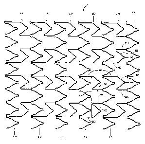
With reference to Figure 1, there is illustrated a two dimensional
representation of a stent 100. By two dimensional representation, is meant a
view of
the stent as obtained by taking a tubular form of the stent, cutting it in a
longitudinal
direction and laying open/flattening the stent.
Stent 100 consists of a series of circumferential rings 110. In the
illustrated
embodiment, there are six circumferential rings 110.
Circumferential rings 110 are interconnected by longitudinal connectors 120.
In the illustrated embodiment, there are two longitudinal connectors that
interconnect
each pair of circumferential rings 120.
Each longitudinal connector 120 consists of a flex member 125 that is
disposed between a pair of straight sections 130,135. Such longitudinal
connectors
are conventional in the art.
The stent design shown in Figure 1 may be regarded as a so-called "peak-to-
valley" design. By this it is meant that longitudinal connector 120 connects a
peak of
circumferential ring 110 with a valley of an adjacent circumferential ring
110. In
general, peak-to-valley designs are known in the art.
When stent 100 is bent, a number of problems are encountered.
With reference to Figure 2, stent 100 is shown in a bent state ¨ this bent
stent
configuration is consistent with the type of bending often encountered during
clinical
use of stent 100. As illustrated, a problem results in that various of
circumferential
rings 110 contact or "crash" on the adjacent circumferential ring 110. For
clarity, this
is illustrated by circles A. As illustrated, during "crashing", the crowns
(peaks) of
adjacent circumferential rings contact each other and overlap and/or kink.
This can
create significant problems for the physician trying to implant stent 100. If
the stent is
to be implanted in a curved lumen, "crashing" results in interruption of blood
flow
and increased risk of thrombosis. Even if the stent is to be implanted
elsewhere in the
body (e.g., a relatively straight body lumen), if adjacent circumferential
rings kink and
become entangled, there is a risk that they will not untangle thereby
compromising the
ability of the stent to return to a proper straight configuration.
11
CA 02750228 2013-08-13
Further, while the bent configuration shown in Figure 2 allows stent 100
generally to maintain its tubular configuration, the crashing of adjacent
pairs of
circumferential rings 110 adversely affects the flexibility of the stent and,
can cause
tangling of the crowns that in some cases, can result in damage to the stent.
Tangling
(resulting from "crashing") of adjacent pairs of circumferential rings in the
stent can
also lead to the circumferential rings being out of axial alignment. If this
is not
noticed by the physician, it can lead to potentially disastrous results for
the patient as
a result of fracture, strut protrusion through artery wall, increased risk of
embolism/thrombosis.
A more significant clinical problem with stent 100 can be seen with reference
to Figure 3. Here, stent 100 is shown in a bent state in an artery 10. As was
seen in
Figure 2, in this configuration, there is crashing of adjacent circumferential
rings 110
(see circles A). In addition, a further problem can be seen. Specifically,
circumferential ring 110* actually rotates out of the tubular configuration to
be in
alignment with the longitudinal axis of the stent. This is clearly not an
acceptable
configuration of the stent and it cannot be correctly implanted in a safe
manner when
such a problem occurs. This problem is even more likely to occur clinically
than
"crashing" discussed above. When the problem does occur, it will not
necessarily
self-correct and, in most cases, would require some sort of intervention
(possibility
surgery) to remove an incorrectly implanted stent. In many cases, this exposes
the
patient to the very risk that was intended to be avoided by attempting an
endovascular
intervention.
Thus, while stent 100 illustrated in Figures 1-3 is very flexible, this high
degree of flexibility appears to give rise to the crashing problem (Figures 2
and 3) and
the "out of tubular configuration" problem (Figure 3).
To overcome this problem, one could attempt to increase the number of
longitudinal connectors used to connect each adjacent pair of circumferential
rings ¨
such a design is illustrated in Figure 4.
Thus, in Figure 4, there is illustrated a stent 200 having six circumferential
rings 210. Circumferential rings 210 are similar to circumferential rings 110
in
12
CA 02750228 2013-08-13
Figures 1-3. A series of longitudinal connectors 220 interconnect adjacent
pairs of
circumferential rings 210.
The difference between the stent designs in Figures 1-3 and that in Figure 4
is
that there are two longitudinal connectors 120 connecting each pair of
circumferential
rings 110 in stent 100 shown in Figures 1-3. In contrast, there are three
longitudinal
connectors 220 interconnecting each pair of circumferential rings 210 in stent
200
shown in Figure 4.
The result of adding an additional longitudinal connector 220 is significant.
As shown in Figure 5, when stent 200 is bent, the "crashing" problem and the
"out of
tubular configuration" problem seen with stent 100 in Figures 1-3 is overcome.
However, this comes at a cost of flexibility of stent 200. As can be seen in
Figure 5,
when stent 200 is bent, the inner portion of the stent which forms the apex of
the bend
is susceptible to kinks ¨ this is shown in circle B in Figure 5. This problem
results
due to the less flexible nature of stent 200. For example, it can be seen in
Figure 5
that there is very little uniform bending of stent 200. Rather, it appears
that most of
the bending forces are concentrated in the region of stent 200 shown in circle
B. To
achieve bending of stent 200 high force is typically needed. Thus, there can
be too
much stress applied to the artery leading to clinical complications such as
dissection,
rupture or other acute/chronic injury to the artery. Further, there is a risk
of flexure
fatigue failure associated with the region of stent 200 shown in circle B.
Still further,
there is excessive protrusion of elements of the region of stent 200 shown in
circle B
leading to an increased risk of thrombosis and/or limitation/denial of access
to the
distal portion of the lumen in which stent 200 is implanted.
This results in a compromise in the conformability of the stent. As is known
in the art, "conformability" refers to the ability of the stent to conform to
the shape of
the vessel as opposed to forcing the vessel to conform to the shape of the
stent. In
summary, there is a problem on the one hand of great flexibility but
crashing/out of
tubular configuration associated with the stent shown in Figures 1-3 while, on
the
other hand, there is the problem with kinking and lack of conformability
associated
with the stent shown in Figures 4-5. At least with respect to the stents
illustrated in
13
CA 02750228 2013-08-13
=
Figures 1-5, these problems depend on whether there are two or three
longitudinal
connectors interconnecting adjacent circumferential rings.
With reference to Figure 6, there is illustrated a stent 400 shown in a bent
state
¨ this bent state is similar to the described above with reference to Figures
2, 3 and 5
described above. Stent 400 is a stent product commercially available from
OptiMed
under the tradename "Sinus-XL stent" and is often implanted by a physician in
the
aorta of a patient, typically in a straight portion of that lumen. This stent
is not well
suited for delivery and/or implantation through/in a curved lumen.
Specifically, the
"Instructions For Use" contained with the product include the following
statements:
"The sinus-XL stem' is marked by its inflexible sinus wave structure.
Thus, it must not be implanted at a joint or nearby a joint or in case of
severe vessel/lumen curvatures."
The reason for this cautionary instruction is apparent with reference to
Figure
6 which illustrates the Sinus-XL stent in a bent configuration. As shown,
there is
significant kinking of stent 400 in the apex region of the bend and, after
repeated
bending, various struts in the device actually fractured. As is further
apparent, the
relatively tight porous pattern of the device when placed across a branch
artery raises
the risk of compromising the access to the side branch it is covering ¨ this
is
particularly problematic if the stent is implanted in the aorta and crosses
various of the
arteries branching off the aorta. In such a case, the physician is likely
blocked from
access to the covered arteries (know in the art as being "jailed in" and the
like), thus
preventing the interventional treatment of that artery in the future.
Thus, there does remain a need in the art for a stent design which has an
improved balance between flexibility and conformability without causing
problems
associated with crashing and out of tubular configuration described above. It
would
be particularly advantageous if these attributes of the stent did not
compromise the
crimpability of the stent. It would be further particularly advantageous if
the stent
was relatively resistant to kinking during bending while maintaining good wall
apposition and desirable side branch access.
14
CA 02750228 2013-08-13
With reference to Figures 7-12, there is illustrated a stent 300 which accords
with the preferred embodiment of the present invention. In Figure 7 stent 300
is
shown in an expanded state.
As seen in Figure 8, in two dimensions, stent 300 consists of a series of
circumferential rings 310. Adjacent pairs of circumferential rings 310 are
interconnected by a series of longitudinally extending portions 320. In the
illustrated
embodiment, there are four longitudinally extending portions 320 that
interconnect
with each pair of circumferential rings 310.
Each longitudinally extending portion 320 consists of a pair of longitudinally
extending struts 325,330. In each longitudinally extending portion 320,
longitudinally
extending struts 325,330 are circumferentially offset with respect to each
other and
are interconnected by a connecting portion 335. Connecting portion 335
contains at
least one apex 340.
Adjacent pairs of longitudinally extending portions 320 are arranged in a
specific manner. More particularly, circumferentially spaced pairs of
longitudinally
extending portions 320 are arranged so that a pair of a longitudinally
extending struts
330 are spaced at a first distance C and a pair of longitudinally extending
struts 325
are spaced at a distance D. As shown, distance C is greater than distance D.
When stent 300 is bent (Figure 9), it generally maintains is tubular
configuration ¨ i.e., the conformability of stent 300 is quite good. The poor
conformability and kinking problem described above with respect to stent 200
in
Figures 4-5 and stent 400 in Figure 6 is reduced or avoided. In addition, the
crashing
and out of tubular configuration problem described above with respect to stent
100 in
Figures 1-3 is reduced or avoided. This is primarily due to the design of
longitudinally
extending portions 320 and the orientation of circumferentially adjacent pairs
of
longitudinally extending portions 320 (as discussed above), which allows for
necessary expansion when stent 300 is placed under tension and contraction
when
stent 300 is placed under compression. These longitudinal tension and
compression
forces are experienced when the stent 200 is placed on a curve as show in
Figure 9.
CA 02750228 2013-08-13
Figures 10-12 show in detail how the longitudinally extending portions allow
for this
expansion and contraction.
Thus, stent 300 provides a combination of advantages that is not seen as such
with stent 100 in Figures 1-3 or stent 200 in Figures 4-5 or stent 400 in
Figure 6.
Figure 11 illustrates stent 300 in a neutral configuration ¨ i.e., there are
no
stresses placed on the stent. In this configuration, peaks 345,350 in an
adjacent pair
of longitudinally adjacent circumferential rings 310 are spaced at a first
distance E.
When stent 300 is placed under tension (which occurs along the larger radius
of a
bend) (Figure 10), longitudinally adjacent peaks 345,350 of a longitudinally
adjacent
pair of circumferential rings 310 are longitudinally spaced at a distance F
that is
greater than E in Figure 11. As is also apparent from Figure 10, the distance
between
circumferentially adjacent pairs of apices 340 in longitudinally extending
portions 320
increases when stent 300 is placed under longitudinal tension.
With reference to Figure 12, it can be seen that when stent 300 is placed
under
compression (which occurs along the smaller radius of a bend), longitudinally
adjacent peaks 345,350 in a longitudinally adjacent pair of circumferential
rings 310
are spaced at a distance G which is less than distance E in the neutral
configuration of
stent 300 (Figure 11). In addition, it can be seen that the distance between
circumferentially adjacent pairs of apices 340 in adjacent longitudinally
extending
portions 320 generally decreases when stent 300 is placed under longitudinal
compression.
This dynamic behaviour of the longitudinal connectors 320 when the stent is
placed under compression or tension can be regarded as a pivoting action which
improves the flexibility and conformability of stent 300 while minimizing or
reducing
having struts in the stent to contact or crash on each other. This advantage
is also
illustrated in Figure 8 which shows stent 300 on a curve.
With reference to Figures 13-15, there is illustrated a series of alternatives
to
longitudinally extending portions 320 illustrated in Figures 7-12.
16
CA 02750228 2013-08-13
Thus, in Figure 13(a), longitudinally extending portion 320 is illustrated as
a
starting point for modification. In Figures 13(b) through 13(d), there is
shown
modifications to longitudinally extending struts 325,330. In Figure
13(b),
longitudinally extending strut 325 is modified to include a curved flex member
327
that is located between a pair of straight portions 328 and 329. Summarily,
longitudinally extending strut 330 has been modified to include a curved flex
member
332 that is located between a pair of straight sections 333 and 334.
While flex members 327,332 in Figures 13(b) are depicted as S-shaped
portions, it will be appreciated by those of skill in the art that the
specific nature of the
curved flex member may be modified and includes the various shapes of "flexure
means" described and illustrated in United States patent 6,858,037 [Penn et
al.
(Penn)].
In Figure 13(c), longitudinally extending struts 325,330 have been modified
such that each are substantially completely curved. In the illustrated
embodiment, the
struts have been modified to have a general S-shape. Of course, other curved
shapes
can be used.
In Figure 13(d), only strut 330 has been modified and it has a general C-
shape,
wherein there is no distinguishable transition between struts 330 and
connecting
portion 335.
In Figures 14(b) and 14(c), there are illustrated modifications to connecting
portion 335 of longitudinally extending portion 320 to include curved portions
that are
shown in Figures 13(b) and 13(c), respectively. In Figures 15(b) through
15(e), there
are illustrated modifications to apex 340 of longitudinal extending portion
320.
Thus, in Figure 15(b), the apex of connecting portion 335 has been modified
to be pointed. In Figure 15(c), this apex is flat. In Figure 15(d), this apex
has been
modified to have a pair of curved portions with a dimple in between. Finally,
in
Figure 15(e), the apex has been modified to have a flat portion with a curved
flex
member disposed therein.
17
CA 02750228 2013-08-13
Those of skill in the art will recognize it is possible to modify
longitudinally
extending portion 320 to include one or more of the features described in
Figures 13-
15. That is, it is possible to combine the various modifications shown in
Figures 13-
15 in a single longitudinally extending portion 320. Further, it is possible
to modify
the connecting portion between circumferential ring 310 and longitudinally
extending
portion 320 to have an apex similar to apex 340 comprised in connecting
portion 320.
in addition to the above stated advantages associated with stent 300, there is
a
further advantage. Specifically, stent 300, having circumferential rings 310
of similar
profile and amplitude, can be readily crimped while reducing or avoiding pre-
deployment crashing of the various struts in the design. This can be seen with
reference to Figure 16.
The stent of the present invention may further comprise a coating material
thereon. The coating material can be disposed continuously or discontinuously
on the
surface of the stent. Further, the coating may be disposed on the interior
and/or the
exterior surface(s) of the stent. The coating material can be one or more of a
biologically inert material (e.g., to reduce the thrombogenicity of the
stent), a
medicinal composition which leaches into the wall of the body passageway after
implantation (e.g., to provide anticoagulant action, to deliver a
pharmaceutical to the
body passageway and the like) and the like.
The stent is preferably provided with a biocompatible coating, in order of
minimize adverse interaction with the walls of the body vessel and/or with the
liquid,
usually blood, flowing through the vessel. A number of such coatings are known
in
the art. The coating is preferably a polymeric material, which is generally
provided
by applying to the stent a solution or dispersion of preformed polymer in a
solvent
and removing the solvent. Non-polymeric coating materials may alternatively be
used.
Suitable coating materials, for instance polymers, may be
polytetraflouroethylene or
silicone rubbers, or polyurethanes which are known to be biocompatible.
Preferably,
however, the polymer has zwitterionic pendant groups, generally ammonium
phosphate ester groups, for instance phosphoryl choline groups or analogues
thereof.
18
CA 02750228 2013-08-13
Examples of suitable polymers are described in International application
number WO-A-93/16479 and WO-A-93/15775. Polymers described in those
specifications are hemo-compatible as well as generally biocompatible and, in
addition, are lubricious. It is important to ensure that the surfaces of the
stent are
completely coated in order to minimize unfavourable interactions, for instance
with
blood, which might lead to thrombosis. This good coating can be achieved by
suitable
selection of coating conditions, such as coating solution viscosity, coating
technique
and/or solvent removal step.
In another embodiment of the invention, the stent may be joined to a cover
material to form a so-called stent graft. The cover may be a polymer or non-
polymer
material and it may be natural or synthetic. Non-limiting examples of suitable
covering materials include bovine, basilic vein or other natural tissue, PTFE,
e-PTFE,
polyurethane, GortexTM, bioabsorbable materials and the like. The cover
material
may be secured to the inside or the outside of the stent. Of course it is also
possible to
form a laminate construction wherein the a pair of cover materials (similar or
dissimilar) sandwich or otherwise surround at least a portion of the stent.
The cover
material may be secured to the stent by bonding, suturing, adhesion,
mechanical
fixation or any combination of these. Further, if the cover material is a
polymer
material, it may be extruded onto the stent in such a manner that it envelops
at least a
portion of the stent. This technique may be used to join two or more stents
with a
flexible polymeric tube. This technique may also be used to join a stent to
another
prosthetic device such as a tube, a graft and the like. Thus, in this
embodiment of the
invention, the stent is incorporated into an endoluminal prosthesis. The cover
materials may fully or partially cover the stent in the radial and/or
circumferential
direction.
The manner by which the present stent is manufactured is not particularly
restricted. Preferably, the stent is produced by laser cutting techniques
applied to a
tubular starting material. Thus, the starting material could be a thin tube of
a metal or
alloy (non-limiting examples include stainless steel, titanium, tantalum,
nitinol,
Elgiloy, NP35N, cobalt-chromium alloy and mixtures thereof) which would then
have
sections thereof cut out to provide a stent having a pre-determined design.
19
CA 02750228 2013-08-13
Thus, the preferred design of the present stent is one of a tubular wall which
is
distinct from prior art wire mesh designs wherein wire is conformed to the
desired
shape and welded in place. The preferred tubular wall design of the present
stent
facilitates production and improves quality control by avoiding the use of
welds and,
instead, utilizing specific cutting techniques.
In one embodiment, the present stent is configured to be a balloon expandable
stent. In this embodiment, the stent can be made from a balloon expandable
material
such as stainless steel, titanium, tantalum, nitinol (certain grades),
Elgiloy, NP35N,
cobalt-chromium alloy and the like. The present stent may be implanted using a
conventional system wherein a guidewire, catheter and balloon can be used to
position and expand the stent. Implantation of mono-tubular stents such as
this stent is
conventional and within the purview of a person skilled in the art. See, for
example,
any one of United States patents 4,733,665, 4,739,762, 5,035,706, 5,037,392,
5,102,417, 5,147,385, 5,282,824, 5,316,023 and any of the references cited
therein or
any of the references cited herein above. Alternatively, the present stent may
be
manufacture from non-metal (e.g., polymer) materials and/or materials that are
b ioab sorbab le .
It will be apparent to those of skill in the art that implantation of stent of
the
present can be accomplished by various other means. For example, it is
contemplated
that the stent can be made of a suitable material which will expand when a
certain
temperature is reached. In this embodiment, the material may be a metal alloy
(e.g.,
nitinol) capable of self-expansion at a temperature of at least about 20 C,
preferably in
the range of from about 20 C to about 37 C. In this embodiment, the stent
could be
implanted using a conventional catheter and the radially outward force exerted
on the
stent would be generated within the stent itself. Further, the present stent
can be
designed to expand upon the application of mechanical forces other than those
applied
by a balloon/catheter. For example, it is possible to implant the present
stent using a
catheter equipped with a resisting sleeve or retaining membrane which may then
be
removed with the catheter once the stent is in position thereby allowing the
stent to
expand. Thus, in this example, the stent would be resiliently compressed and
would
self-expand once the compressive force (i.e., provided by the sleeve or
membrane) is
CA 02750228 2013-08-13
removed. This is known as a self-expanding stent. Additional details on this
approach may be found in United States patents 5,067,957 and 6,306,141.
Finally, it is preferred to incorporate one or more radioopaque markers in the
present stent to facilitate view thereof during angiography typically used to
guide the
device to its intended location in the patient. It is particularly preferred
to have at
least one radioopaque marker at or near each of the proximal and distal ends
of the
stent. The material used as the radioopaque is preferably selected from the
group
consisting of gold, platinum, iridium, tantalum and tungsten.
While this invention has been described with reference to illustrative
embodiments and examples, the description is not intended to be construed in a
limiting sense. Thus, various modifications of the illustrative embodiments,
as well
as other embodiments of the invention, will be apparent to persons skilled in
the art
upon reference to this description.
21