Note: Descriptions are shown in the official language in which they were submitted.
CA 02750268 2012-03-13
CONTROLLED DEFLECTION GOGGLE
BACKGROUND
Field of the Inventions
[0001] The present inventions relate generally to eyewear products. More
specifically, the present inventions relate to methods and apparatuses for
controlling the
deflection of a lens in order to optimize the optical quality of the lens and
to provide a
customized fit for the wearer.
Description of the Related Art
[0002] A wide variety of improvements have been made in recent years in
the
eyewear field, particularly with respect to eyewear intended for use in active
sports,
including goggles and sunglasses. Many improvements have been made with
respect to
lens molding technology and fashion sunglasses as well. These improvements
have been
incorporated into eyewear having both a unitary lens and dual lens design. As
a result,
modern active sport eyewear is functionally superior to its predecessor
eyewear in
numerous ways, such as by maximizing interception of peripheral light,
reducing optical
distortion, and increasing the wearer's comfort level.
[00031 For example, lens designs for both dual and unitary eyewear
designs
can provide fhll side-to-side range of vision and good lateral eye protection
while
providing superior optical performance. More particularly, in a unitary lens
system, the
angle of incidence from the wearer's eye to the posterior lens surface changes
as the
wearer's line of sight turns in either the vertical or the horizontal planes.
This results in
disparate refraction between light entering closer to the front of the lens
and peripheral
light entering at the lateral ends. To address this source of prismatic
distortion, U.S.
Patent No. 4,859,048 discloses tapering the thickness of the lens from the
medial portion
toward the lateral edge.
[0004] Further, various improvements have also been made in lens
mounting
technology that allow mounted lenses to retain their superior optical
characteristics
provided by their as-molded geometry. For example, the dual lens "Racing
Jacket'
manufactured by Oakley, Inc. incorporates a lens suspension design that
mitigates any
-1-
CA 02750268 2012-03-13
mounting stresses on the lens in order to allow the lens to float and retain
its as-molded
geometry. Such systems are disclosed in U.S. Patent Application No.
61/078,326, titled
Floating Lens Mounting System, filed July 3, 2008.
[0005] Finally, numerous modifications have been made to eyeglass and
goggle products in an effort to make these products more comfortable for the
wearer. For
example, different materials have been used in the manufacture of frames and
lenses in
order to decrease the weight and improve the touch and feel of these products.
These
technological improvements can be incorporated into any variety of dual or
unitary lens
designs, whether for eyeglass or goggle products, in order to provide a wearer
with a
comfortable, optically superior eyewear product.
SUMMARY
[0006] In accordance with at least one embodiment disclosed herein is
the
realization that a customizable eyewear product can sometimes experience
undesirable
distortion when fitted to a wearer's unique profile. This distortion can
sometimes cause
discomfort for the wearer as well as inferior optical performance of the
eyewear product.
At least some of the embodiments of the inventions disclosed herein enable the
eyewear
product to exhibit enhanced structural properties in order to prevent
discomfort and to
maintain preferred optical characteristics of the eyewear product.
[0007] For example, a goggle is a customizable eyewear product that can
be
adjusted to fit a wearer's head by adjusting a strap of the goggle. Goggle
applications
include skiing, motocross, underwater diving masks, and a variety of
industrial safety
applications such as welding and for power equipment operators. Typically,
goggles offer
sealed protection to the eyes and adjacent areas of the wearer's face against
particulate
matter or water, without providing full head protection. This geometry allows
the lens to
closely conform to the wearer's face and intercept light, wind, dust, etc.
from directly in
front of the wearer (anterior direction) and peripherally (lateral direction).
Accordingly, it
is quite important that they goggle closely conform to the face of the wearer
during use.
As such, a wearer commonly adjusts the elastic strap of the goggle to tightly
press the
goggle to the wearer's face.
-2-
CA 02750268 2011-07-21
WO 2010/085416 PCT/US2010/021033
[0008] A goggle usually comprises an arcuate unitary lens which extends
across both the wearer's right and left eye fields of view. The lens can be
supported by a
frame, which typically surrounds the lens. The lens and the frame are both
configured
with a downwardly concave indent for receiving the nose. The rear surface of
the frame,
normally covered with a foam component or other compressible padding, is
adapted to
contact the wearer's face. Finally, an elastic strap is connected to the
opposing lateral
sides or ends of the frame in order to allow the goggle to be worn.
[0009] In use, the surface of the foam component or other compressible
padding disposed at the rear of the goggle makes contact with the wearer's
face. The
wearer-contacting surface has a radius of curvature in the horizontal plane
that is adapted
to conform from side to side to the wearer's face. When the goggle is placed
on a wearer
with a "narrow" head, the tension from the straps extending around the back of
the
wearer's head can cause the lateral sides of the goggle to bend medially,
thereby wrapping
the goggle into a tighter radius of curvature to fit the wearer.
[0010] In many common goggles, the vertical height of the lens above the
nose
opening is significantly less than the vertical height of the lens in the
wearer's straight
ahead line of sight. Therefore, a goggle worn on a narrow head can tend to
crease or bend
preferentially about a vertical midline through the lens at the nose opening,
especially
given the rearward traction on the lateral sides of a goggle caused by the
straps of the
goggle. This deforms the lens geometry and creates optical distortion. This
also causes a
narrowing in the width of the nose opening, which in turn pinches the nose of
the wearer.
[0011] Furthermore, a goggle can often exhibit severe prismatic distortion
due
to the bending force exerted by the strap on ends of the goggle frame to
secure the goggle
on the wearer's head. As noted above, the goggle can often be forced to
conform to a
tighter radius of curvature as the goggle conforms to the head of the wearer.
Consequently, the lens mounted in the goggle frame can likewise experience
deformation
that results in reduced optical performance, such as optical distortion and
prismatic shift.
[0012] Thus, in accordance with the present inventions, there is provided a
goggle that comprises a reinforcement structure for preventing preferential
bending of the
goggle about the midpoint of its lens, as the lateral edges of the goggle are
deflected in a
medial direction. This may be accomplished, for example, by insert molding a
relatively
rigid support rib or element within the goggle frame, centered over the
nosepiece. The
length of the support rib may be less than half of the overall side to side
arc length of the
-3-
CA 02750268 2011-07-21
WO 2010/085416 PCT/US2010/021033
frame, and serves to inhibit preferential bending about the vertical midline
of the goggle.
Alternatively, the support may be formed within or adjacent the lower portion
of the
goggle frame, or may be secured directly to the lens, spanning the midline of
the goggle.
[0013] In some embodiments, a goggle is provided that comprises a goggle
frame and a bend control component. The goggle frame can define opposing
lateral
portions and a central portion. The goggle frame can comprise a bridge
disposed at the
central portion of the goggle frame. The goggle frame can be generally
flexible upon
exertion of a bending force on the goggle frame. Further, the bend control
component can
extend along the bridge of the goggle frame. The bend control component can
comprise a
generally elongate body having first and second ends. The first and second
ends can be
disposed on opposing sides of the bridge. The bend control component can be
configured
to enhance flexural strength of the goggle at the bridge thereof for reducing
preferential
bending of the goggle frame at the bridge. Optionally, the goggle can comprise
a cushion
component that can be attached to the goggle frame and configured to be
interposed
between the goggle frame and a wearer's face.
[0014] In some embodiments, the bend control component can be attached to
the goggle frame. In this regard, the bend control component can be formed
separately
from the goggle frame as an insert for the goggle frame. The goggle frame can
be
configured to receive at least a portion of the bend control component for
mounting the
bend control component on the goggle frame. The bend control component and the
goggle frame can also be formed from a monolithic piece of material.
[0015] The goggle frame can define an upper portion and a lower portion,
and
the bend control component can be disposed adjacent to the upper portion of
the goggle
frame. Otherwise, the goggle frame can define an upper portion and a lower
portion, and
the bend control component can be disposed adjacent to the lower portion of
the goggle
frame. However, it is also contemplated that the bend control component can
extend
along both the upper and lower edges or portions of the goggle frame.
[0016] The goggle frame and the bend control component can be fabricated
from the same or different materials. For example, the goggle frame can be
fabricated
from a first material and the bend control component can be fabricated from a
second
material that has a flexural strength greater than a flexural strength of the
first material.
The first and second materials can be polymers, metals, composites, and/or
other
materials.
-4-
CA 02750268 2011-07-21
WO 2010/085416 PCT/US2010/021033
[0017] The goggle frame and the bend control component can be configured
such that a flexural strength of the goggle at the bridge is at least equal to
a flexural
strength of the goggle along the lateral portions thereof. Further, the goggle
frame and the
bend control component can be configured such that the flexural strength of
the goggle at
the bridge is greater than to the flexural strength of the goggle along the
lateral portions
thereof.
[0018] In some embodiments, the bend control component can comprise a
plurality of tabs extending from the elongate body thereof. The tabs can be
configured to
engage respective recesses formed in the goggle frame for coupling the bend
control
component to the goggle frame. The tabs of the bend control component can be
disposed
intermediate the first and second ends thereof.
[0019] In accordance with some embodiments, the goggle frame can comprise
first and second lens support portions and a bridge disposed between the first
and second
lens support portions. The first and second lens support portions of the
goggle frame can
be configured to support at least one lens in the field of view of the wearer.
The bridge
can form a nosepiece indentation. The goggle frame can be generally flexible
in response
to a bending force exerted on the bridge of the goggle frame. The at least one
lens and the
first lens support portion can collectively provide a first composite flexural
strength. The
at least one lens and the second lens support portion can collectively provide
a second
composite flexural strength. The at least one lens and the bridge can provide
a bridge
flexural strength. Finally, the bend control component can be disposed on the
bridge of
the goggle frame adjacent to the nosepiece indentation thereof. The bend
control
component can flex with the bridge of the goggle frame in response to the
bending force
exerted on the bridge of the goggle frame. The bend control component can
provide
flexural strength in addition to the bridge flexural strength to collectively
provide a third
composite flexural strength. In this regard, the third flexural strength can
be equal to or
greater than either of the first or second composite flexural strengths to
enhance flexural
strength of the goggle at the bridge to reduce preferential bending of the
goggle frame at
the bridge.
[0020] In some embodiments, the bend control component can be formed
separately from the goggle frame. The bend control component can comprise an
elongate
body that defines at least one tapering dimension. For example, a width of the
bend
control component can taper from a central portion thereof toward opposing
ends thereof.
-5-
CA 02750268 2011-07-21
WO 2010/085416 PCT/US2010/021033
Further, the width of the bend control component can narrow from the central
portion
toward the opposing ends thereof.
[0021] In some embodiments, the goggle can comprise a fastener, the goggle
frame can comprise a fastening cavity, and the bend control component can
comprise at
least one aperture. In this regard, the fastener can be configured to be
seated within the
fastening cavity of the goggle frame and to engage the aperture of the bend
control
component for attaching the bend control component to the goggle frame. In
some
embodiments, the goggle frame can be interposed between the fastener and the
bend
control component.
[0022] In accordance with some embodiments, the goggle can comprise one or
more engagement structures. The bend control component can comprise an
elongate body
and one or more engagement members disposed along the body thereof The goggle
frame can comprise a nosepiece section and an engagement recess extending
along the
nosepiece section. The engagement recess can be configured to receive at least
a portion
of the bend control component. The one or more engagement structures can
corresponding to the engagement members of the bend control component. The
engagement structures can be configured to secure the bend control component
within the
engagement recess of the goggle frame. In this embodiment, the bend control
component
can provide supplemental flexural strength to the goggle frame for reducing
preferential
bending of the frame at the nosepiece section.
[0023] In some embodiments, one or more engagement members of the bend
control component can comprise one or more protrusions extending from the
elongate
body thereof Accordingly, one or more engagement structures can comprise one
or more
recesses configured to receive the one or more protrusions of the bend control
component
for securing the bend control component to the engagement recess of the goggle
frame.
[0024] In some embodiments, one or more engagement members of the bend
control component can comprise one or more recesses in the elongate body
thereof.
Accordingly, one or more engagement structures can comprise one or more
protrusions
extending within the engagement recess of the goggle frame and being
configured to
engage with the one or more recesses of the bend control component.
[0025] Further, the one or more engagement structures can be formed
monolithically with the goggle frame.
-6-
CA 02750268 2012-03-13
[0026] The one or more engagement structures can also comprise at least one
fastener. The fastener can comprise a protrusion configured to extend through
an
aperture of the goggle frame and into a faster recess of the bend control
component
for securing the bend control component to the goggle frame. The goggle frame
can also
comprise a protruding member that can define an aperture. The protruding
member can
be receivable within the fastener recess of the bend control component for
securing the
bend control component to the goggle frame. Additionally, the protruding
member of
the goggle frame can be expandable upon insertion of the protrusion of the
fastener to
create interference fit between the protruding member of the goggle frame and
the
fastener recess of the bend control component for securing the bend control
component
in the goggle frame.
In accordance with an aspect of the present invention there is provided a
goggle comprising: a goggle frame defining opposing lateral portions and a
central
portion, the goggle frame comprising a bridge disposed at the central portion
of the
goggle frame, the goggle frame being generally flexible upon exertion of a
bending force
on the goggle frame; and a bend control component extending along the bridge
of the
goggle frame, the bend control component comprising a generally elongate body
having
first and second ends, the bend control component being configured to enhance
flexural
strength of the goggle at the bridge thereof for reducing bending of the
goggle frame at
the bridge.
In accordance with a further aspect of the present invention there is provided
a
goggle comprising: at least one lens; a goggle frame comprising first and
second lens
support portions and a bridge disposed between the first and second lens
support
portions, the first and second lens support portions of the goggle frame being
configured
to support the at least one lens in the field of view of the wearer, the
bridge forming a
nosepiece indentation, the goggle frame being generally flexible in response
to a bending
force exerted on the bridge of the goggle frame, the at least one lens and the
first lens
support portion collectively providing a first composite flexural strength,
the at least one
lens and the second lens support portion collectively providing a second
composite
flexural strength, the at least one lens and the bridge providing a bridge
flexural strength;
and a bend control component disposed on the bridge of the goggle frame
adjacent to the
nosepiece indentation thereof, the bend control component flexing with the
bridge of the
goggle frame in response to the bending force exerted on the bridge of the
goggle frame,
the bend control component providing flexural strength in addition to the
bridge flexural
strength to collectively provide a third composite flexural strength; wherein
the third
-7-
CA 02750268 2013-12-31
flexural strength is at least equal to either of the first or second composite
flexural
strengths to enhance flexural strength of the goggle at the bridge to reduce
bending of the
goggle frame at the bridge.
In accordance with a further aspect of the present invention there is provided
a
goggle comprising: a bend control component comprising an elongate body and
one or
more engagement members disposed along the body thereof; a goggle frame
comprising
a nosepiece section and an engagement recess extending along the nosepiece
section, the
engagement recess being configured to receive at least a portion of the bend
control
component; and one or more engagement structures corresponding to the
engagement
members of the bend control component, the engagement structures configured to
secure
the bend control component within the engagement recess of the goggle frame;
wherein
the bend control component provides supplemental flexural strength to the
goggle frame
for reducing bending of the frame at the nosepiece section.
In accordance with a further aspect of the present invention there is provided
a
goggle comprising: a goggle frame defining opposing lateral portions and a
central portion,
the goggle frame comprising a bridge disposed at the central portion of the
goggle frame,
the goggle frame being generally flexible upon exertion of a bending force on
the goggle
frame, the goggle frame comprising a front frame portion and a rear frame
portion spaced
apart from the front frame portion, the front frame portion being configured
to support a
lens in a wearer's line of sight, the rear frame portion being adjustable
relative to the
contours of the wearer's face; a bend control component extending along the
bridge of the
front frame portion and being spaced apart from the rear frame portion of the
goggle frame,
the bend control component comprising a generally elongate body having first
and second
ends, the first and second ends being disposed on opposing sides of the
bridge, the bend
control component being configured to enhance flexural strength of the goggle
at the
bridge thereof for reducing bending of the front frame portion of the goggle
frame at the
bridge; and a cushion component attached to the rear frame portion of the
goggle frame
and configured to be interposed between the goggle frame and the wearer's
face.
In accordance a further aspect of the present invention here is provided a
goggle
comprising: at least one lens having a stiffness; a goggle frame having a
front frame
portion and a rear frame portion spaced apart from the front frame portion,
the rear frame
portion being adjustable relative to the contours of a wearer's face, the
front frame
portion of the goggle frame being configured to support the at least one lens
in the field
7a
CA 02750268 2013-12-31
of view of the wearer, the bridge forming a nosepiece indentation, the goggle
frame
being generally flexible in response to a bending force exerted on the bridge
of the
goggle frame; and
a bend control component disposed along the bridge of the front frame portion
of
the goggle frame adjacent to the nosepiece indentation thereof and generally
below the at
least one lens, the bend control component having a stiffness that is
approximately
greater than the stiffness of the at least one lens, the bend control
component flexing with
the bridge of the front frame portion of the goggle frame in response to the
bending force
exerted on the bridge of the front frame portion of the goggle frame; the
front frame
portion of the goggle frame being configured to support the at least one lens
in the field
of view of the wearer, the bridge forming a nosepiece indentation, the goggle
frame
being generally flexible in response to a bending force exerted on the bridge
of the
goggle frame; and a bend control component disposed along the bridge of the
front frame
portion of the goggle frame adjacent to the nosepiece indentation thereof and
generally
below the at least one lens, the bend control component having a stiffness
that is
approximately greater than the stiffness of the at least one lens, the bend
control
component flexing with the bridge of the front frame portion of the goggle
frame in
response to the bending force exerted on the bridge of the front frame portion
of the
goggle frame to enhance flexural strength of the goggle at the bridge to
reduce bending
of the goggle frame at the bridge.
In accordance with a further aspect of the present invention there is provided
a
goggle comprising: a bend control component comprising an elongate body and
one or
more engagement members disposed along the body thereof; a goggle frame
comprising
a front frame portion configured to support a lens and having a nosepiece
section and an
engagement recess extending along the nosepiece section, the engagement recess
being
configured to receive at least a portion of the bend control component, the
goggle frame
further comprising a rear frame portion spaced apart from the front frame
portion, the
rear frame portion being adjustable relative to the contours of a wearer's
face; a cushion
component attached to the rear frame portion and configured to be interposed
between
the goggle frame and the wearer's face; and one or more engagement structures
corresponding to the engagement members of the bend control component, the
engagement structures configured to secure the bend control component within
the
engagement recess of the front frame portion of the goggle frame; wherein the
bend
control component provides supplemental flexural strength to the front frame
portion of
the goggle frame for reducing bending of the frame at the nosepiece section.
-7b-
CA 02750268 2013-12-31
BRIEF DESCRIPTION OF THE DRAWINGS
[0027] The
abovementioned and other features of the inventions disclosed
herein are described below with reference to the drawings of the preferred
embodiments.
The illustrated embodiments are intended to illustrate, but not to limit the
inventions. The
drawings contain the following figures:
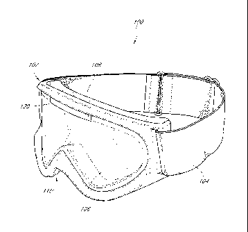
[0028] Figure 1 is a perspective view of a prior art goggle.
[0029] Figure 2 is a front view of the goggle shown in Figure 1.
[0030] Figure 3 is
a cross-sectional top view taken along the lines 3-3 of
Figure 2.
[0031] Figure 4 is
a cross-sectional top view of the goggle as shown in Figure
3 wherein bending forces F, F are exerted on the goggle.
[0032] Figure 5 is
a top view of the goggle of Figure 1 being worn on the head
of a wearer.
[0033] Figure 6 is
a perspective view of a goggle made in accordance with an
embodiment of the present inventions.
[0034] Figure 7 is a front view of the goggle shown in Figure 6,
[0035] Figure 8 is a side view of the goggle shown in Figure 6.
[0036] Figure 9 is
a cross-sectional top view of the goggle showed in Figure 6.
[0037] Figure 10
is a cross-sectional top view of the goggle shown in Figure 6
wherein bending forces F, F are exerted on the goggle.
[0038] Figure 11
is a top view of the goggle of Figure 6 being worn on the
head of a wearer.
-7c-
CA 02750268 2011-07-21
WO 2010/085416 PCT/US2010/021033
[0039] Figures 12-15 illustrate embodiments of a bending control component
that can be incorporated into a goggle made in accordance with an embodiment
of the
present inventions.
[0040] Figure 16 is a perspective view of another goggle made in accordance
with another embodiment.
[0041] Figure 17 is a front view of the goggle shown in Figure 16.
[0042] Figure 18 is an exploded view illustrating components of the goggle
shown in Figure 16.
100431 Figure 19 is a perspective view of an embodiment of a bend control
component that can be used in various embodiments of a goggle.
[0044] Figure 20 is a front view of the bend control component shown in
Figure 19.
[0045] Figure 21 is a cross-sectional side view of the goggle shown in
Figure
17, taken along section lines 21-21 of Figure 17, according to an embodiment.
[0046j Figure 22 is an enlarged view of a portion of the cross-sectional
side
view of the goggle shown in Figure 21.
DETAILED DESCRIPTION
[0047] While the present description sets forth specific details of various
embodiments, it will be appreciated that the description is illustrative only
and should not
be construed in any way as limiting. Additionally, it is contemplated that
although
particular embodiments of the present inventions may be disclosed or shown in
the
context of unitary or dual lens eyewear systems, such embodiments can be used
in both
unitary and dual lens eyewear systems. Further, it is contemplated that
although particular
embodiments of the present inventions may be disclosed or shown in the context
of
frames having a full orbital, whether in a goggle or sunglass, such
embodiments can be
used with frames having both full and partial orbitals. Furthermore, various
applications
of such embodiments and modifications thereto, which may occur to those who
are skilled
in the art, are also encompassed by the general concepts described herein.
[0048] As discussed above, many prior art goggle designs have the comment
deficiency of allowing preferential bending at a midpoint of the goggle frame.
Such
preferential bending results in an inferior fit, reduced optical quality, and
may even cause
physical and optical discomfort for the wearer. Therefore, in accordance with
at least one
-8-
CA 02750268 2011-07-21
WO 2010/085416 PCT/US2010/021033
of the embodiments disclosed herein is the realization that the preferential
bending of
prior art goggle frames can be reduced and/or eliminated in order to enhance
the comfort
and performance of a goggle.
100491 Figures 1-5 illustrate a common prior art goggle design. Figure 1
illustrates a goggle 10 that comprises a goggle frame 12, an elastic strap 14,
and a foam
component 16 attached to a posterior portion of the goggle frame 12. The
goggle frame
12 also comprises an indent or nosepiece 18. In use, the wearer will position
the goggle
frame 12 onto her face and adjust the elastic strap 14 around the back of her
head in order
to firmly but comfortably secure the goggle frame in place. Figure 5
illustrate a top view
of a wearer's head 40 onto which the goggle 10 has been placed.
[0050] The foam component 16 is intended to contact the wearer's face and
allow the goggle 10 to conform to the surface of the wearer's face. However,
as discussed
below, gaps can frequently be formed between the foam component 16 and the
surface of
the wearer's face due to the preferential bending of the goggle 10.
Furthermore, the
preferential bending can also cause certain portions of the foam component 16
to be
highly compressed while other portions are not compressed at all. In this
regard, the foam
component 16 will fail to properly distribute stresses along the surface of
the wearer's face
resulting in stress concentrations along side of the wearer's head, such as
the sides of the
forehead, temples, and cheekbones. The realization that such stress
concentrations are
created due to the preferential bending of the goggle frame 12 represents an
aspect of at
least one embodiment of the present inventions disclosed herein.
[0051] With reference to Figure 3, a cross sectional top view of the goggle
10
is shown. As illustrated, a lens 20 of the goggle 10 is mounted in the goggle
frame 12.
Figure 3 illustrates the goggle frame 12 and the lens 20 in an unloaded
position. In other
words, the goggle frame 12 and the lens 20 are not bent from their as-molded
configuration. As such, at least lateral portions 22, 24 of the lens 20 can be
configured to
define a common center of curvature A in this example. In the as-molded
configuration, a
medial section 26 of the lens 20 defines a preferred geometry that can provide
desirable
optical characteristics for the goggle 10.
[0052] However, in Figure 4, the lens 20 of the goggle 10 is shown in a
loaded
position. The loaded position is generally assumed when the goggle 10 is
positioned on
the head of the wearer. As illustrated in Figure 4, bending forces F, F can be
exerted on
the lateral sides of the frame 12 and resulted in bending of the frame 12 and
the lens 20.
-9-
CA 02750268 2012-03-13
These forces F, F can be caused by the elastic strap 14 during use of the
goggle 10 by
the wearer.
100531 When the goggle frame 12 and the lens 20 are bended in the loaded
position, prior art goggles generally exhibit preferential bending at a
midpoint 28 of
the lens 20. In accordance with at least one embodiment disclosed herein is
the
realization that a disadvantage such preferential bending at the midpoint 28
of the
lens 20 results in bending of the frame 12 at the nosepiece 18. As shown in
Figure 2,
the nosepiece 18 has an unloaded geometry that defines a given width.
Generally, the
nosepiece 18 allows the wearer to comfortably position the goggle 10 on the
bridge
of the wearer's nose. However, preferential bending of the frame 12 will
generally
cause the width of the nosepiece 18 to decrease. As a result, the wearer's
nose may be
pinched and create discomfort for the wearer.
[0054] Additionally, the preferential bending also causes the centers
of
curvature of the lateral portions 22,24 of the lens 20 to be significantly
displaced
from the common center of curvature A to the displaced centers of curvature B,
C.
The medial section 26 of the lens 20 is also significantly deformed from its
unloaded
position. This deformation of the lens 20 substantially worsens the original
or as-
molded optical characteristics of the lens 20.
100551 For example, the lens 20 can exhibit substantial prismatic
shift and
other optical distortions that tend to tire the eyes of the wearer and reduce
the wearer's
ability to accurately perceive the position of objects. These disadvantages
may not
only make use of the goggle 10 uncomfortable, but can potentially affect the
wearer's
performance of a given activity. In fast-paced activities, such as skiing,
snowboarding,
skydiving, and the like, where goggles are commonly used, the disadvantages
caused
by preferential bending of the lens 20 and the frame 12 can be exacerbated.
[0056] Figure 5 illustrates yet another disadvantage of such a prior
art
goggle 10. The top view of Figure 5 shows a goggle 10 that has been fitted
onto a
wearer's head 40. Due to the preferential bending of the goggle 10, the foam
component 16 can often experience excessive compression along medial portions
60
of the foam component 16. However, more centralized portions 62 of the foam
component 16 may actually be separated from the wearer's forehead 64 by a gap
66.
Although the gap 66 may be minor, such gapping can be problematic in cold
weather
or water-related applications, such as skiing and scuba diving. In such
applications,
any gapping can result in impaired vision.
-10-
CA 02750268 2011-07-21
WO 2010/085416 PCT/US2010/021033
Further, the uneven compression of the foam component 16 can create uneven
stresses
and stress concentrations at certain points that are exerted against the
wearer's head. As a
result, the wearer will generally experience greater discomfort and fatigue.
[00571 In accordance with at least one embodiment disclosed herein is the
realization that the preferential bending of the goggle 10 is caused at least
in part because
the central section of the goggle 10 where the nosepiece 18 is located as a
flexural
strength that is less than the flexural strength of other portions of the
goggle 10.
[0058] With reference again to Figure 2, vertical lines A, B, C illustrate
sections of the goggle 10 at which the flexural strength of the goggle 10 can
be measured.
The flexural strength can be defined as the ability of the goggle 10 to resist
bending
around a vertical axis at a given location along the goggle 10. Such bending
is illustrated
in Figures 3 and 4. Thus, the vertical lines A, B, C can represent vertical
axes about
which the goggle 10 can be bent at the flexural strength at that location can
be measured.
Additionally, the flexural strength of the goggle 10 at a given location can
generally be a
product of the materials and dimensions of the components used in the goggle
10 at the
given location.
[00591 For example, vertical lines A are disposed adjacent to edges of
opposing lateral sides of the lens 20 of the goggle 10. The flexural strength
of the goggle
at this location may be relatively low compared to portions of the goggle 10
at vertical
lines B. At vertical lines A, the lens height is neither a minimum or a
maximum.
However, vertical lines B are disposed along the goggle 10 generally where the
lens 20
reaches a maximum height. Finally, vertical lines C are disposed along the
goggle 10
generally where the lens 20 reaches a minimum height.
[0060] At each of these locations, the height of the lens 20 and the upper
and
lower portions of the goggle frame 12 will contribute to the flexural strength
of the goggle
10. Therefore, by comparison, the flexural strength of the goggle 10 at the
vertical lines B
will be greater than the flexural strength of the goggle 10 at the vertical
lines A and C.
Additionally, the flexural strength of the goggle 10 at the vertical lines A
will be greater
than the flexural strength of the goggle 10 at the vertical lines C. These
differences in
flexural strengths result in part because of the height difference of the lens
20 at these
locations. Indeed, there is less lens material available to contribute to the
flexural strength
of the goggle 10 at the vertical line C as compared with the vertical lines B.
-11-
CA 02750268 2011-07-21
WO 2010/085416 PCT/US2010/021033
[0061] As a result, the flexural strength of such a prior art goggle 10
will
consistently be at a minimum at the central portion or nosepiece 18 of the
goggle 10.
Consequently, the bending forces experienced during normal use will cause the
goggle 10
to preferentially bend at the central portion or nosepiece 18 of the goggle
10. The above-
mentioned problems therefore ensue from these prior art goggles.
[0062] Therefore, in accordance with at least one embodiment disclosed
herein, an improved goggle is provided that comprises a reinforced central
portion
configured such that the flexural strength of the central portion is at least
equal to the
flexural strength of other portions of the goggle. In this regard, embodiments
disclosed
herein will tend not to exhibit preferential bending at the central portion or
nosepiece of
the goggle. Specifically, some embodiments disclosed herein provide for a
goggle having
a central section or nosepiece section that exhibits higher relative flexural
strength than
other portions of the goggle. More specifically, other embodiments disclosed
herein
provide for a goggle having a reinforced nosepiece section that prevents
undesirable
bending of the goggle at the nosepiece section that otherwise results in
pinching of the
wearer's nose, discomfort, and lens distortion.
[0063] The central portion of the goggle can comprise a zone or section of
the
goggle generally extending from the straight ahead line of sight of one eye of
the wearer
to the straight ahead line of sight of the other eye of the wearer. In other
words, the
central portion of the goggle 300 can generally comprise the central one-half
to two-thirds
portion of the goggle.
[0064] Referring now to Figure 6, an embodiment of an improved goggle 100
is illustrated. The goggle 100 comprises a goggle frame 102, a strap 104, at
least one lens
106, and a cushion component 108. Additionally however, the goggle 100 is
configured
to provide bend control of the goggle frame 102 at the central portion of the
goggle frame.
For example, the bend control can be provided at the nosepiece indentation,
bridge, or
nosepiece section 110. As used herein, nosepiece indentation, bridge, or
nosepiece
section can refer to the feature shown as element 110. In some embodiments,
the goggle
frame 102 can comprise a bend control component. Such embodiments utilize the
bend
control component of the goggle frame 102 to provide bend resistance or
additional
flexural strength during normal use to mitigate and/or prevent the above-noted
problems
of prior art goggles, such as discomfort to the wearer and excessive lens
distortion when
the goggle is adjusted to fit a given wearer.
-12-
CA 02750268 2011-07-21
WO 2010/085416 PCT/US2010/021033
[0065] In some embodiments, the bend control of the goggle frame 102 can be
implemented by adjusting one or more dimensions of the goggle frame 102. In
other
words, the goggle frame 102 can comprise a monolithically formed bend control
component. For example, the geometry of the frame can be adjusted to
compensate for
decreased lens height at the central portion or nosepiece section of the
goggle.
Alternatively, the material from which the frame is fabricated can be varied
to provide
additional flexural strength at the central portion or nosepiece section of
the goggle. As
such, some embodiments can provide for a goggle having a central portion or
nosepiece
section that exhibits a generally fixed flexural strength that is greater than
the flexural
strength of the goggle at other locations along the goggle. Thus, such
embodiments
would mitigate and/or prevent preferential bending of the goggle at the
central portion or
nosepiece section of the goggle.
[0066] However, in other embodiments, the goggle frame 102 can comprise a
separately formed bend control component that can be attached to the goggle
frame 102
can provide bend control of the goggle 100. Such an embodiment is illustrated
in Figure
6. As shown, the goggle frame 102 can comprise a bend control component 120.
The
bend control component 120 can be attached to the goggle 100. For example, the
bend
control component 120 can be adhesively joined or mechanically coupled with
the goggle
frame 102. Further, it is contemplated that the bend control component 120 can
also be a
peaceably joined or mechanically coupled with other portions of the goggle
100, such as
the lens 116 (with a single or double lens configuration, for example).
100671 Figures 7-8 illustrate front and side views of the embodiment of the
goggle 100 shown in Figure 6. As illustrated in Figure 7, the lens 106 can be
a unitary
lens and the goggle frame 102 can be configured to surround the lens 106. As
such, the
goggle frame 102 can comprise a lower portion 130 and an upper portion 132.
The
goggle frame 102 can comprise first and second lens support portions located
on either
side of the nosepiece section 110. Thus, although the embodiment illustrates a
unitary
lens, it is contemplated that embodiments disclosed herein can also be
utilized with a dual
lens goggle, whether or not single or double lens layers are used.
[0068] As illustrated, the bend control component 120 can be attached to
the
upper portion 132 of the goggle 100. However, in other embodiments, the bend
control
component 120 can be attached to the lower portion 130 of the goggle frame
102. In yet
other embodiments, the bend control component 120 can comprise one or more
-13-
CA 02750268 2011-07-21
WO 2010/085416 PCT/US2010/021033
components that are attached to both of the lower and upper portions 130, 132
of the
goggle 100.
100691 In some embodiments, the bend control component 120 can extend
along a central portion 134 of the goggle 100. For example, the bend control
component
120 can extend between approximately 1-3 inches along the central portion 134.
In
embodiments where the bend control component 120 is positioned along the upper
portion 132 of the goggle 100, the bend control component 120 may generally
comprise
an elongate straight shape. However, in other embodiments where the bend
control
component 120 is positioned along the lower portion 130 of the goggle 100, the
bend
control component 120 can also be formed in eight and one linear shape, such
as an
inverted V shape that generally follows the contour of the nosepiece section
110. Further,
the bend control component 120 may preferably be centered relative to a
centerline of the
goggle frame 102.
[0070] In yet other embodiments, it is contemplated that the bend control
component 120 can extend along greater than just a portion of the periphery of
the goggle
100. For example, the bend control component 120 can be a retrofit component
that
attaches to opposing lateral sides of the goggle and extends adjacent to the
perimeter of
the goggle frame 102.
[0071] Additionally, as shown in Figure 8, the bend control component 120
can be attached to an anterior portion 136 of the goggle frame 102.
Nevertheless, it is
contemplated that other embodiments can be configured such that the bend
control
component 120 is attached to a posterior portion 138 of the goggle frame 102.
[0072] Figures 9-10 illustrate cross-sectional top views of the goggle 100.
In
Figure 9, the goal 100 is shown in an unloaded position. Thus, the frame 102,
the lens
106, and the bend control component 120 not experiencing flexural stress
resulting from
use by the wearer. In some embodiments, the frame 102, the lens 106, and the
bend
control component 102 can be substantially free of stress in the unloaded
position.
However, in other embodiments, it is contemplated that the frame 102, the lens
16, and/or
the bend control component 102 can be assembled in a pre-stressed condition
which may
aid in mitigating and/or preventing preferential bending of the goggle 100
about the
central portion or nosepiece section.
[0073] Figure 10 illustrates the goggle 100 in a loaded position. In other
words, the goggle 100 is an as-worn loaded position in which forces F, F act
along lateral
-14-
CA 02750268 2011-07-21
WO 2010/085416 PCT/US2010/021033
portions of the frame 102 to cause the goggle 100 to bend. However, with the
bend
control component 120 in place, the goggle 100 will not tend to preferentially
bend at the
central portion or nosepiece section. In other words, as shown in Figure 10,
the bending
of the goggle 100 will be distributed through side and lateral portions of the
goggle frame
102 and the lens 106.
[0074] Accordingly, the bending of the goggle 100 in response to such
forces
F, F can be controlled in order to thereby mitigate and/or prevent collapse of
the
nosepiece opening of the nosepiece section 110 and pinching of the nose of the
wearer.
Further, dramatic optical distortion can also be prevented. In particular,
with the bend
control component 120 extending along the central portion 134 of the goggle
100, the lens
106 can tend to retain its unloaded position. Thus, the optical quality of the
lens at the
wearer's straight ahead line of sight may be generally undiminished from the
unloaded to
the loaded position.
[0075] Furthermore, Figure 11 illustrates that in use, embodiments of
the
goggle can also tend to create even distribution of compressive forces through
the cushion
component 108. The cushion component 108 can be fabricated from a foam
material or
other resilient material. In other words, in contrast to the prior art goggles
discussed
above, embodiments of the goggles disclosed herein will not tend to create
gapping
between the wearer's face and the cushion component 108. Additionally, because
compressive forces are evenly distributed through the cushion component 108,
no stress
concentrations are likely to be present that would create discomfort and
fatigue for the
wearer. These, and other advantages, can be obtained through implementations
of various
embodiments of the goggles disclosed herein.
[0076] Figure 12-15 illustrate various embodiments of a bend control
component. Figures 12-13 and 15 illustrate bend control components that have a
constant
height or vertical dimension, and therefore, only a cross-sectional top view
of these
components is shown in order to illustrate a width of these components. As
discussed
below, the bend control components shown in Figures 13 and 15 and a variable
width that
varies from a central portion thereof towards opposing ends thereof. However,
as
discussed below, Figure 14 illustrates a bend control component that has a
constant width
and a variable height or vertical dimension that varies from a central portion
thereof
towards opposing ends thereof. Each of the embodiments shown in Figures 12-15
can
-15-
CA 02750268 2011-07-21
WO 2010/085416 PCT/US2010/021033
provide distinct advantages and represent alternative configurations of the
bend control
component.
[0077] Initially however, it is noted that a goggle frame and the lens
of some
embodiments are configured to provide a nosepiece opening or nosepiece
section. The
flexural strength of the goggle varies from a centerline of the goggle toward
the opposing
ends thereof. Indeed, as shown in Figure 7, the flexural strength of the
goggle initially
increases from section A to section B of the goggle. However, if the bend
control
component is not used, as in the prior art, the flexural strength of the
goggle may decrease
from section B to section C of the goggle.
[0078] Therefore, in accordance with at least one of the embodiments
disclosed herein is the realization that the bend control component can be
specifically
configured to correspond with the flexural strength of the goggle at a given
point or
section. The flexural strength of the bend control component will be additive
to the
flexural strength of the goggle at a given point or section. Thus, the
collective or overall
flexural strength of the goggle can be represented by a summation of the
individual
flexural strengths of the bend control component and the goggle at a given
point or
section.
[0079] For example, in sonic embodiments, the bend control component
can
be configured to provide a supplementary flexural strength to the central
portion or
nosepiece section of the goggle such that the goggle has a generally constant
overall
flexural strength along the central portion or nosepiece section of the
goggle. In other
words, while in some embodiments the bend control component can itself have a
constant
flexural strength along the length thereof, in other embodiments, the bend
control
component can be configured such that it has a variable flexural strength
along the length
thereof Such a variable flexural strength can therefore correspond to and/or
supplement a
variable flexural strength of the central portion or nosepiece section of a
goggle, and
together, the central portion or nosepiece section of the goggle and the bend
control
component can collectively define a constant overall flexural strength. In
this regard, the
overall flexural strength can be defined as the sum of the flexural strength
of the bend
control component and the flexural strength of the goggle at a given point
along the
goggle; and the flexural strength of the goggle can be defined as the
composite or sum of
the flexural strengths of the lens and the frame at a given point along the
goggle. As
discussed above, in some embodiments, the overall flexural strength can
advantageously
-16-
CA 02750268 2011-07-21
WO 2010/085416 PCT/US2010/021033
be configured to prevent and/or mitigate preferential bending of the goggle at
the central
portion or nosepiece section thereof.
[0080] With reference now to various embodiments of the bend control
component, Figure 12 illustrates a cross-sectional top view of a bend control
component
200 that has a constant cross-sectional width 202. Using the bend control
component 200,
the goggle would have a reinforced in flexural strength along the central
portion thereof.
However, although such an embodiment may prevent and/or mitigate preferential
bending
at the central portion or nosepiece section, it may not produce a constant
overall flexural
strength along the goggle.
[0081] Figure 13 illustrates a cross-sectional top view of another
embodiment
of a bend control component 210 that has a variable width 212. The width 212
tapers
from a central portion of the bend control component 210 toward opposing ends
thereof
As a result of the variable width 212, the bend control component 210 will
provide a
variable flexural strength along its length. Accordingly, the bend control
component 210
can be configured such that its variable flexural strength corresponds to a
variable flexural
strength of the goggle along the central portion or nosepiece of section
thereof.
100821 Figure 14 illustrates a perspective view of yet another
embodiment of a
bend control component 216. The bend control component 216 can comprise a
variable
height 218. The height 218 tapers from a central portion of the bend control
component
216 towards opposing ends thereof. As illustrated, the height 218 can vary
along a length
of the bend control component 216. However, in such an embodiment, the width
of the
component can be generally constant. Therefore, the variable height will allow
the bend
control component 216 to have a variable flexural strength along the length of
the bend
control component 216. As noted above, the variable flexural strength can
correspond to
a variable flexural strength of the goggle along the central portion or
nosepiece section
thereof
[0083] Figure 15 illustrates a cross-sectional top view of yet another
embodiment of a bend control component 220 that defines a generally constant
width 222,
but also comprises a series of notches 224. In some embodiments, the notches
can be
spaced evenly along the length of the bend control component 220. However, in
the
illustrated embodiment, the notches 224 are spaced at decreasing intervals
from the center
of the bend control component 220 towards the opposing ends thereof The
notches 224
can directly affect the flexural strength of the bend control component 220 at
a given
-17-
CA 02750268 2011-07-21
WO 2010/085416 PCT/US2010/021033
point along its length. For example, the illustrated embodiment of the bend
control
component 220 can produce a generally variable flexural strength along the
length of the
component 220. Again, as noted above, the variable flexural strength can
correspond to a
variable flexural strength of the goggle along the central portion or
nosepiece section
thereof.
[0084] Figures 16 and 17
illustrate yet another embodiment of a goggle 300
that can be configured to reduce and/or eliminate preferential bending of the
goggle 300 at
a central portion or nosepiece section thereof. The goggle 300 can comprise a
goggle
frame 302, a strap 304, a cushion component 306, at least one lens 308, and a
nosepiece
section 310 disposed along a central portion of the goggle 300. As used
herein, nosepiece
indentation, bridge, or nosepiece section can refer to the feature shown as
element 310.
The goggle frame 302 can comprise lateral portions or first and second lens
support
portions located on either side of the nosepiece section 310. Thus, although
the
embodiment illustrates a unitary lens, it is contemplated that embodiments
disclosed
herein can also be utilized with a dual lens goggle, whether or not single or
double lens
layers are used.
[0085] As noted above,
the central portion of the goggle 300 can comprise a
zone or section of the goggle generally extending from the straight ahead line
of sight of
one eye of the wearer to the straight ahead line of sight of the other eye of
the wearer. In
other words, the central portion of the goggle 300 can generally comprise the
central two-
thirds portion of the goggle 300.
[0086] As discussed above
with respect to the embodiment illustrated in
Figures 6-11, the embodiment shown in Figures 16-21 can advantageously prevent
and/or
mitigate this comfort to the wearer, optical distortion, and other
disadvantages associated
with preferential bending of the goggle at the central portion or nosepiece
section thereof.
The embodiment of Figures 16-21 illustrates a modular goggle 300 that is
configured to
provide bend control of the goggle to enhance the flexural strength of the
goggle along the
central portion or nosepiece section of the goggle.
[0087] For example,
Figure 17 illustrates vertical sections A, B, C. as
discussed above with respect to the embodiment of Figures 6-11, the goggle 300
can be
configured such that the flexural strength of the goggle 300 is not at a
minimum at section
A of the goggle 300. In other words, the flexural strength at sections B and C
can be
generally equal to or less than the flexural strength of the goggle at section
A.
-18-
CA 02750268 2012-03-13
[0088] Referring to Figure 18, components of the goggle 300 are shown in
an exploded perspective view. In this figure, and embodiment is illustrated in
which
the at least one lens and foam component has been removed in order to
illustrate a
bend control assembly 320 and the frame 302 by themselves. Thus, in this
embodiment, while it is contemplated that the lens(es) and/or the foam
component can
contribute to the flexural strength of the goggle, these components have been
omitted
to illustrate the bend control assembly 320 and the frame 302 by themselves.
Further,
the bend control assembly 320 can comprise at least a bend control component
or
insert 330. Further, in some embodiments, the bend control assembly 320 can
also
comprise one or more fasteners 332. For example, the illustrated embodiment
utilizes
both the insert 330 and the fasteners 332 with the goggle frame 302 in order
to provide
bend control of the goggle at the central portion or nosepiece section
thereof.
[0089] Figures 19 and 20 illustrate an embodiment of the bend control
component or insert 330. The perspective view of Figure 19 helps to show
features
and aspects of the bend control component or insert 330. As illustrated, the
bend
control component 330 can comprise a generally elongate body 340. Although the
body 340 can define a generally linear shape, the body 340 of the illustrated
embodiment defines a curvilinear shape that is configured to correspond with
the
curvilinear perimeter of the nosepiece section of the goggle frame. Further,
as
discussed herein, the bend control component 330 can be configured to be
inserted to
within a gap or recess of the goggle frame; accordingly, in such an
embodiment, the
body 340 of the bend control component 330 advantageously can generally
conform
to the overall shape of the nosepiece section of the goggle.
[0090] As also illustrated in Figure 19, the bend control component 330 can
comprise one or more anterior projections 342. The anterior projections 342
can be
configured to engage a corresponding recess or groove of the goggle frame, as
discussed below. Further, the bend control component can also comprise one or
more
lateral projections 344. The lateral projections 344 can be configured to
engage a
corresponding recess or group of the goggle frame, as also discussed below.
[0091] Although in this embodiment, the anterior projections 342 and the
lateral projections 344 are used to engage corresponding portions of the
goggle frame
to allow the bend control component 330 to be seated at engage with the goggle
frame, it is contemplated that the goggle frame could use one or more
projections that
engage
-19-
CA 02750268 2012-03-13
corresponding recesses in an embodiment of the bend control component 330. In
other words, the bend control component could alternatively utilize anterior
and
lateral recesses that engage corresponding protrusion of the goggle frame. In
this
regard, the illustrated embodiment of the bend control component 330 can
comprise
one or more engagement recesses 346. The engagement recesses 346 can be
configured to receive a corresponding protrusion or structure of the goggle
frame for
aligning and/or engaging the bend control component 330 with the goggle
frame. Various other modifications or substitutions can be utilized to provide
functional embodiments of the bend control component 330.
[0092] Additionally, in some embodiments, the bend control component 330
can also comprise a mating edge or shelf 348. The mating edge or shelf 348 can
define a
limit position for the bend control component 330 as it engages the goggle
frame.
Further, at some embodiments the mating edge or shelf 348 can be configured
such that
by limiting downward movement of the bend control component 330 relative to
the
goggle frame when engaged with each other, rattling due to vibration can be
mitigated.
[0093] Figures 19 and 20 also illustrate that the bend control component 330
can comprise one or more fastener recesses 350. The fastener recesses 350 can
be
configured so as to be engaged by a fastener extending through the goggle
frame such that
the bend control component can be fixed in place relative to the goggle frame.
As noted
above with respect to the projections, the fastener recesses 350 could be
replaced with one
or more projections that could extend through a corresponding recess of the
goggle frame
to be engaged by a fastening component, such as a threaded nut.
[0094] Figures 21-22 are cross-sectional side views of the goggle 300. These
figures illustrate the alignment and engagement of the various components of
the goggle
300. For example, the cross-sectional view illustrates that two unitary lenses
308 can be
used in the goggle 300. The lens is 308 can be separated by a gasket 360 and
mounted in
the goggle frame 302. Further, Figure 21 also illustrates that the cushion
component 306
can comprise a plurality of layers. In this regard, the cushion component 306
can be
fabricated from one or more types of foam materials or resilient materials.
[0095] Figure 22 is an enlarged view of the cross-sectional view of Figure 21.
These figures illustrate an embodiment in which the bend control component 330
is
received and engaged with an engagement recess of the goggle frame 302. As
shown in
Figure 22, an anterior projection 342 of the bend control component can engage
a
corresponding recess 370 of the goggle frame 302. Further, the fastener 332
can be
-20-
CA 02750268 2012-03-13
received and seated within an external recess 374 of the goggle frame 302. As
shown, the
fastener 332 can serve to secure the bend control component to the goggle
frame 302.
[0096] In accordance with an embodiment, a protrusion 380 of the fastener 332
can
extend through an aperture of a protruding member 382 of the goggle frame 302.
Also, as
shown, the protruding member 382 of the goggle frame comprises both an
aperture and a
posteriorly extending body. Further, Figure 22 illustrates that the fastener
recess 350 of the
bend control component 330 can be configured to receive at least a portion of
the protruding
member 382 therein. This initial engagement between the protruding member 382
and the
fastener recess 350 can provide a first degree of retention between the goggle
frame 302 and
the bend control component 330. Thus, even without the use of the fastener
332, the
protruding member 382 of the goggle frame can be used to engage the engagement
aperture
350 of the bend control component 330.
[0097] However, a unique aspect of at least one embodiments disclosed herein
is that the protrusion 380 of the fastener 332 can be urged through the
aperture of the
protruding member 382 to cause the posteriorly extending body to expand and
forcibly
engage the fastener recess of the bend control component 330. In other words,
the protrusion
380 of the fastener 332 can be configured to define a passing profile or outer
dimension that
is slightly greater than the inner profile of the aperture of the protruding
member 382.
Further, the protruding member 382 can comprise a resilient material that
allows the
protruding member 382 to expand upon insertion of the protrusion 380 into the
aperture
thereof. In this regard, the protruding member 382 can also comprise one or
more slits that
extend along the length of the posteriorly extending body of the protruding
member 382. The
expansion and interference fit created by insertion of the protrusion 380 into
the protruding
member 382 can create a second degree of retention between the goggle frame
302 and the
bend control component 330.
[0098] Accordingly, after inserting the bend control component 330 into the
engagement recess 362 of the goggle frame 302, the fastener 332 can be
inserted into the
external recess 374 of a goggle frame 302. As the fastener 332 is urged
further into the
external recess 374, the protrusion 380 of the fastener 332 is urged through
the aperture of the
protruding member 382, causing the protruding member 382 to expand and create
an
interference fit with the fastener recess 350 of the bend control component
330.
[0099] However, in some embodiments the fastener 332 need not create an
interference fit with the protruding member 382 and the fastener recess 350.
Instead, the
-21-
CA 02750268 2011-07-21
WO 2010/085416 PCT/US2010/021033
fastener 332 can comprise a protrusion that extends through the goggle frame
302 and the
fastener recess 350. The protrusion of the fastener 332 can comprise a bulbous
head that
resists retraction from engagement with the fastener recess 350 of the bend
control
component 330. However, some embodiments, it is also contemplated that the
fastener
332 can comprise another component that attaches to a distal end of the
protrusion of the
fastener 332 once the fastener 332 is seated or received with any external
recess 374 and
the fastener recess 350. Thus, the fastener 332 can secure the bend control
component
within the engagement recess 362 of the goggle frame 302.
[01001 Although these inventions have been disclosed in the context of
certain
preferred embodiments and examples, it will be understood by those skilled in
the art that
the present inventions extend beyond the specifically disclosed embodiments to
other
alternative embodiments and/or uses of the inventions and obvious
modifications and
equivalents thereof In addition, while several variations of the inventions
have been
shown and described in detail, other modifications, which are within the scope
of these
inventions, will be readily apparent to those of skill in the art based upon
this disclosure.
It is also contemplated that various combination or sub-combinations of the
specific
features and aspects of the embodiments may be made and still fall within the
scope of the
inventions. It should be understood that various features and aspects of the
disclosed
embodiments can be combined with or substituted for one another in order to
form
varying modes of the disclosed inventions. Thus, it is intended that the scope
of at least
some of the present inventions herein disclosed should not be limited by the
particular
disclosed embodiments described above.
-22-