Language selection

Search

Patent 2750472 Summary

Third-party information liability

Some of the information on this Web page has been provided by external sources. The Government of Canada is not responsible for the accuracy, reliability or currency of the information supplied by external sources. Users wishing to rely upon this information should consult directly with the source of the information. Content provided by external sources is not subject to official languages, privacy and accessibility requirements.

Claims and Abstract availability

Any discrepancies in the text and image of the Claims and Abstract are due to differing posting times. Text of the Claims and Abstract are posted:

  • At the time the application is open to public inspection;
  • At the time of issue of the patent (grant).
(12) Patent: (11) CA 2750472
(54) English Title: WELL JET PUMPING ASSEMBLY FOR DEGASSING COAL BEDS
(54) French Title: ENSEMBLE POMPES A JET POUR PUITS DESTINE AU DEGAZAGE DE COUCHES DE CHARBON
Status: Expired and beyond the Period of Reversal
Bibliographic Data
(51) International Patent Classification (IPC):
  • F04F 5/54 (2006.01)
  • E21B 43/12 (2006.01)
(72) Inventors :
  • DUDNICHENKO, BORIS ANATOLIEVICH (Ukraine)
  • KHOMYNETS, ZINOVIY DMITRIEVICH (Russian Federation)
  • KARASEVICH, ALEKSANDR MIROSLAVOVICH (Russian Federation)
  • KEJBAL, ALEKSANDR VIKTOROVICH (Russian Federation)
(73) Owners :
  • BORIS ANATOLIEVICH DUDNICHENKO
  • ZINOVIY DMITRIEVICH KHOMYNETS
  • ALEKSANDR MIROSLAVOVICH KARASEVICH
  • ALEKSANDR VIKTOROVICH KEJBAL
(71) Applicants :
  • BORIS ANATOLIEVICH DUDNICHENKO (Ukraine)
  • ZINOVIY DMITRIEVICH KHOMYNETS (Russian Federation)
  • ALEKSANDR MIROSLAVOVICH KARASEVICH (Russian Federation)
  • ALEKSANDR VIKTOROVICH KEJBAL (Russian Federation)
(74) Agent: MACRAE & CO.
(74) Associate agent:
(45) Issued: 2014-03-25
(86) PCT Filing Date: 2009-12-16
(87) Open to Public Inspection: 2010-08-05
Examination requested: 2011-07-20
Availability of licence: N/A
Dedicated to the Public: N/A
(25) Language of filing: English

Patent Cooperation Treaty (PCT): Yes
(86) PCT Filing Number: PCT/RU2009/000693
(87) International Publication Number: WO 2010087738
(85) National Entry: 2011-07-20

(30) Application Priority Data:
Application No. Country/Territory Date
2009103029 (Russian Federation) 2009-01-30

Abstracts

English Abstract


A jet pump mounts on a pipe string in a well passing through coal beds. The
pipe
string length is greater than the lower coal bed occurrence depth. A carrying
ring, with
filtering shoe attached on a switcher, mounts below the lower bed floor. A
carrying ring
with bypass ports mounts on the string above the upper bed roof. A packer
mounts on the
string below the ports above the upper bed roof A pump housing with a
removable insert
seat, having a nozzle and a mixing chamber with diffuser, mounts on the ring.
The housing
has a working fluid and exhausted fluid mixture draining channel and an
exhausted fluid
supplying channel, provided with a check valve. The housing connects to a
working fluid
supply pipe provided on the upper end with a sealing element disposed on the
ring, and an
inlet funnel receiving the removable insert.


Claims

Note: Claims are shown in the official language in which they were submitted.

CLAIM
1. .. A well jet assembly for degassing coal beds, the well jet assembly
comprising
a jet pump arranged in a flow string going in a well through coal beds,
characterized in that
the jet pump is arranged in an inner cavity of a lower portion of the flow
string,
which lower portion goes through the coal beds and has a length greater than a
depth of
occurrence of the lowermost coal bed, and
the well jet assembly further comprising
a lower support ring with a filter-type shoe attached via a sub to a lower
part of the
lower support ring, the lower support ring being arranged on a lower portion
of the flow
string below the bottom boundary of the lowermost coal bed,
an upper support ring with drain ports arranged on the flow string higher,
above a top
of the uppermost coal bed,
a packer arranged on an outer surface of the flow string under the drain ports
and
above the top of the uppermost coal bed, and
a body of the jet pump arranged on the lower support ring, said body provided
with:
a seat for installing a removable insert with a nozzle and a mixing chamber
with a
diffuser,
a draining channel for draining a mixture of a working fluid, and
a supply channel for supplying a fluid pumped out of a well and having a check
valve arranged therein,
wherein the body of the jet pump being connected, in its upper part, with a
lower part
of a pipe for supplying a working medium, said pipe being provided with a
sealing element,
said sealing element being arranged on the upper support ring and an input
hopper for
receiving a removable insert.
6

Description

Note: Descriptions are shown in the official language in which they were submitted.


CA 02750472 2013-07-12
WELL JET PUMPING ASSEMBLY FOR DEGASSING COAL BEDS
Field of the Invention
The invention relates to jet engineering and may be used for bottomhole
pumping in wells,
including those intended for producing methane from gas-bearing coal beds.
Description of Prior Art
A well jet pumping unit is known, which comprises an electric centrifugal pump
and a
separator for separating a fluid pumped out of a well into a liquid medium and
a gaseous
medium, said pump and separator being arranged on a pipe string in the well,
wherein said
liquid medium can be pumped out by the electric centrifugal pump and said
gaseous
medium is pumped out by the jet pumping unit (SU 1550115, FO4D 13/10,
03/15/1990).
However, this unit has a relatively low efficiency due to lowering the
efficiency of the
electric centrifugal pump because of forced withdrawal of a significant part
of a liquid
pumped by it for the purpose of operating the jet pumping unit.
The well unit for degassing coal beds (described in RU 2293833, 02/20/2007),
comprising a
pump arranged on a flow string going through coal beds, is accepted to be the
closest prior
art to this invention in terms of its technical essence and achieved result.
Coal-methane wells are characterized by that significant quantities of
powdered coal, fine
coal particles and a dissolved gas are contained in a pumped out formation
water. Therefore,
the use of a sucker-rod pump results in lowering its efficiency and narrows
the possibility of
simultaneous pumping both a liquid medium and a gaseous medium out of a well.
1

CA 02750472 2013-07-12
Summary of the Invention
The aim of this invention is to ensure the possibility of pumping both a
liquid medium and a
gaseous medium out of a well with the use of one pumping assembly, subject to
its long-
term operation.
The claimed technical effect consists in improving the operation efficiency of
the well jet
pumping assembly in the conditions of a liquid phase and a gaseous phase as
well as solid
mechanical impurities present in a fluid pumped out of a well.
The technical effect is achieved due to the fact that a well jet assembly for
degassing of coal
beds comprises a pump arranged in a flow string going in a well through coal
beds, the
pump being a jet pump and arranged in an inner cavity of a lower portion of
the flow string.
The lower portion goes through the coal beds and has a length greater than a
depth of
occurrence of the lowermost coal bed. The well jet assembly further comprises
a lower
support ring with a filter-type shoe attached via a sub to a lower part of the
lower support
ring. The lower support ring is arranged on a lower portion of the flow string
below the
bottom boundary of the lowermost coal bed. The well jet assembly further
comprises an
upper support ring with drain ports arranged on the flow string higher, above
a top of the
uppermost coal bed; a packer arranged on an outer surface of the flow string
under the drain
ports and above the top of the uppermost coal bed; and a body of the jet pump
arranged on
the lower support ring. Said body is provided with: a seat for installing a
removable insert
with a nozzle and a mixing chamber with a diffuser; a channel for draining a
mixture of a
working fluid; and a channel for supplying a fluid pumped out of a well and
having a check
valve arranged therein. The body of the jet pump is connected, in its upper
part, with a lower
part of a pipe for supplying a working medium. The pipe for supplying the
working medium
is provided with a sealing element, wherein said sealing element is arranged
on the upper
support ring and an input hopper for receiving a removable insert.
2

CA 02750472 2013-07-12
Studies have been carried out, which show that there exists the possibility of
pumping out a
liquid medium and then a gaseous medium, in particular methane, from coal beds
with the
use of one well jet pumping assembly. No rearrangement of the equipment is
needed. It has
been found out that the jet pump can be most reasonably installed in the inner
cavity of the
lower portion of the flow string which goes through coal beds and which length
is greater
than the depth of occurrence of the lowermost coal bed. It is most reasonable
when: the
lower support ring, to which lower part a filter-type shoe is attached via a
sub, is arranged
on a lower portion of the flow string below the bottom boundary of the
lowermost coal bed,
the upper support ring with drain ports is arranged on the flow string higher,
above the top
of the uppermost coal bed, the packer is arranged on the outer surface of the
flow string
under the drain ports and above the top of the uppermost coal bed, the body of
the jet pump
is arranged on the lower support ring, said body being provided with: a seat
for installing a
removable insert having a nozzle and a mixing chamber with a diffuser, a
channel for
draining a mixture of a working fluid and a channel for supplying a fluid
pumped out of a
well, said channel for supplying the fluid pumped out of a well having a check
valve
arranged therein, and the body of the jet pump is connected, in its upper
part, to the lower
part of a pipe for supplying a working medium, the pipe being provided with a
sealing
element arranged on the upper support ring and an input hopper for receiving a
removable
insert.
All this enables, on one side, to withdraw a liquid medium, which prevents
degassing of coal
beds, and, on the other side, not to pump a liquid medium, which does not
prevent degassing
of coal beds, out of a well. The making of the well jet assembly with a
lowered removable
insert enables, if necessary, quickly replace it without lifting the whole
flow string with the
pumping assembly to the surface, which enables to improve the productivity of
the pumping
assembly significantly and reduce its operation costs.
Brief Description of the Drawings
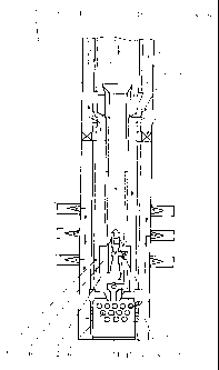
Figure 1 schematically shows the inventive well jet assembly for degassing
coal beds.
3

CA 02750472 2013-07-12
Description of a Best Mode for Carrying Out the Invention
The well jet assembly for degassing of coal beds comprises a pump 2 arranged
on a flow
string 1 going in a well through coal beds, the pump being a jet pump and
being arranged in
the inner cavity of a lower portion of the flow string 1, which goes through
coal beds 3 and
which length is greater than the depth of occurrence of the lowermost coal bed
3. The lower
support ring 4, to which lower part a filter-type shoe 6 is attached via a sub
5, is arranged on
a lower portion of the flow string 1 below the bottom boundary of the
lowermost coal bed 3.
The upper support ring 7 with drain ports 8 is arranged on the flow string 1
higher, above
the top of the uppermost coal bed 3, and a packer 9 is arranged on the outer
surface of the
flow string 1 under the drain ports 8 and above the top of the uppermost coal
bed 3. The
body 10 of the jet pump is arranged on the lower support ring 4, the said body
being
provided with: a seat for installing a removable insert 11 having a nozzle and
a mixing
chamber with a diffuser, a channel 12 for draining a mixture of a working
fluid and a
channel 13 for supplying a fluid pumped out of a well, this channel being
provided a check
valve 14 arranged therein. The body 10 of the jet pump 2 is connected, in its
upper part, to
the lower part of a pipe 15 for supplying a working medium, the pipe 15 being
provided
with a sealing element 16 arranged on the upper support ring 7 and an input
hopper 17 for
receiving a removable insert.
The filter-type shoe 6 with the sub 5, the lower support ring 4, the packer 9
and the upper
support ring 7 with the drain ports 8, which are arranged bottom-up on the
flow string 1, are
lowered into a well thereon.
The body 10 of the jet pump 2 is installed into the inner cavity of the flow
string 1 during
lowering into the well, the lower part of the body being hermetically arranged
on the lower
support ring 4, and then the pipe 15, which is connected to the body 10, is
installed with the
sealing element 16 that is mounted on the upper support ring 7.
Then the removable insert 11 with the nozzle, the mixing chamber and the
diffuser is
dropped into the well, said insert 11 spontaneously arranging itself in the
body 10 of the jet
pump 2 during pumping a liquid in the flow string 1.
4

CA 02750472 2013-07-12
Further, a working agent is supplied under pressure via the flow string 1 to
the nozzle of the
removable insert, thus creating depression in the under-packer area, the
packer 9 being
arranged above the uppermost coal bed 3. As a result, water is drawn from the
bottomhole
via the channel 13 for supplying the medium pumped out of the well into the
mixing
chamber of the insert 11 in the jet pump 2, where it is mixed with the jet
flow of the working
agent and, together with the latter, is delivered via the channel 12, the
annular space around
the pipe 15 and the drain ports 8 into the annular space around the flow
string 1 above the
packer 9 and then comes to the surface via the said annular space. As the
level of a liquid
(water) in the well decreases, coal gas comes via the filter-type shoe 6 into
the jet pump 2,
and the gas, after mixing with the working agent jet flow, also comes to the
surface. Thus,
the liquid, including killing liquid, and the coal gas in the form of a gas-
water mixture are
taken, and then the said mixture is separated into fractions in a gas
separator (not shown in
the Figure) on the surface.
By changing the parameters of the removable insert 11 (e.g., the nozzle
diameter,
replacement of the removable insert 11) and a working agent pumping pressure
in the jet
pump 2 the operation parameters of the jet pump 2 may be easily optimized.
Moreover, the
coal gas is supplied to the surface forcibly, which enables to increase its
output.
If the removable insert 11 fails, or if the water flow rate of the well is
increased
significantly, then the removable insert 11 is extracted to the surface and is
replaced.
Industrial Applicability
The invention may be used in the coal industry during operation of coal
deposits.

Representative Drawing
A single figure which represents the drawing illustrating the invention.
Administrative Status

2024-08-01:As part of the Next Generation Patents (NGP) transition, the Canadian Patents Database (CPD) now contains a more detailed Event History, which replicates the Event Log of our new back-office solution.

Please note that "Inactive:" events refers to events no longer in use in our new back-office solution.

For a clearer understanding of the status of the application/patent presented on this page, the site Disclaimer , as well as the definitions for Patent , Event History , Maintenance Fee  and Payment History  should be consulted.

Event History

Description Date
Time Limit for Reversal Expired 2018-12-17
Letter Sent 2017-12-18
Grant by Issuance 2014-03-25
Inactive: Cover page published 2014-03-24
Inactive: Final fee received 2014-01-13
Pre-grant 2014-01-13
Notice of Allowance is Issued 2013-12-05
Letter Sent 2013-12-05
Notice of Allowance is Issued 2013-12-05
Inactive: Approved for allowance (AFA) 2013-11-14
Inactive: Q2 passed 2013-11-14
Amendment Received - Voluntary Amendment 2013-07-12
Inactive: S.30(2) Rules - Examiner requisition 2013-02-05
Inactive: Cover page published 2012-12-28
Inactive: First IPC assigned 2012-05-24
Inactive: IPC assigned 2012-05-24
Inactive: IPC assigned 2012-05-15
Correct Inventor Requirements Determined Compliant 2011-10-03
Inactive: Acknowledgment of national entry - RFE 2011-09-22
Inactive: Acknowledgment of national entry - RFE 2011-09-08
Letter Sent 2011-09-08
Application Received - PCT 2011-09-08
National Entry Requirements Determined Compliant 2011-07-20
Request for Examination Requirements Determined Compliant 2011-07-20
All Requirements for Examination Determined Compliant 2011-07-20
Small Entity Declaration Determined Compliant 2011-07-20
Application Published (Open to Public Inspection) 2010-08-05

Abandonment History

There is no abandonment history.

Maintenance Fee

The last payment was received on 2013-09-04

Note : If the full payment has not been received on or before the date indicated, a further fee may be required which may be one of the following

  • the reinstatement fee;
  • the late payment fee; or
  • additional fee to reverse deemed expiry.

Please refer to the CIPO Patent Fees web page to see all current fee amounts.

Fee History

Fee Type Anniversary Year Due Date Paid Date
MF (application, 2nd anniv.) - small 02 2011-12-16 2011-07-20
Request for examination - small 2011-07-20
Basic national fee - small 2011-07-20
MF (application, 3rd anniv.) - small 03 2012-12-17 2012-09-27
MF (application, 4th anniv.) - small 04 2013-12-16 2013-09-04
Final fee - small 2014-01-13
MF (patent, 5th anniv.) - small 2014-12-16 2014-09-16
MF (patent, 6th anniv.) - small 2015-12-16 2015-08-05
MF (patent, 7th anniv.) - small 2016-12-16 2016-12-14
Owners on Record

Note: Records showing the ownership history in alphabetical order.

Current Owners on Record
BORIS ANATOLIEVICH DUDNICHENKO
ZINOVIY DMITRIEVICH KHOMYNETS
ALEKSANDR MIROSLAVOVICH KARASEVICH
ALEKSANDR VIKTOROVICH KEJBAL
Past Owners on Record
None
Past Owners that do not appear in the "Owners on Record" listing will appear in other documentation within the application.
Documents

To view selected files, please enter reCAPTCHA code :


To view images, click a link in the Document Description column. To download the documents, select one or more checkboxes in the first column and then click the "Download Selected in PDF format (Zip Archive)" or the "Download Selected as Single PDF" button.

List of published and non-published patent-specific documents on the CPD .

If you have any difficulty accessing content, you can call the Client Service Centre at 1-866-997-1936 or send them an e-mail at CIPO Client Service Centre.


Document
Description 
Date
(yyyy-mm-dd) 
Number of pages   Size of Image (KB) 
Drawings 2013-07-12 1 19
Claims 2013-07-12 1 36
Abstract 2013-07-12 1 20
Representative drawing 2014-02-26 1 9
Cover Page 2014-02-26 1 48
Drawings 2011-07-20 1 60
Description 2011-07-20 5 225
Abstract 2011-07-20 2 143
Claims 2011-07-20 1 33
Representative drawing 2012-05-25 1 28
Cover Page 2012-10-22 1 68
Description 2013-07-12 5 224
Acknowledgement of Request for Examination 2011-09-08 1 177
Notice of National Entry 2011-09-08 1 218
Notice of National Entry 2011-09-22 1 202
Commissioner's Notice - Application Found Allowable 2013-12-05 1 162
Maintenance Fee Notice 2018-01-29 1 183
PCT 2011-07-20 7 223
Correspondence 2014-01-13 1 34