Note: Descriptions are shown in the official language in which they were submitted.
CA 02750665 2016-04-22
SYRINGE
The invention relates to a syringe.
Syringes of the type discussed herein are known in the art. They comprise a
syringe
cylinder and a distal end following thereto that is designed as a syringe
cone. The
distal end comprises a region that is set back in a radial direction, and
wherein ¨
seen in axial direction ¨ an edge is formed extending in the circumferential
direction.
Especially if the body of the syringe is comprised of glass, for manufacturing
reasons
and/or due to the stresses existing inside the material, it is not possible to
configure
this edge with an acute angle and/or at a right angle. Such an edge therefore
comprises a chamfer and/or has ¨ seen in the longitudinal section ¨ the shape
of a
ramp. The syringe has an attachment piece that comprises a clamping region.
When
the attachment piece is separated from the syringe, preferably the clamping
region
has an inside diameter that is smaller than the outside diameter of the region
that is
set back in a radial direction at the distal end of the syringe. When the
attachment
piece is placed onto the syringe in such a way that the clamping region
engages with
the region that is radially set back, there results an expansion of the
clamping region
in a radial direction in such a way that holding forces are introduced into
the radially
set-back region of the syringe. The clamping region comprises a distal edge.
Overall, the attachment piece is held to the body of the syringe by two
mechanisms:
on the one hand, a frictional grip exists between the clamping region and the
region
of the distal end of the syringe that is set back in a radial direction; on
the other
hand, the distal edge of the clamping region is able to engage with the edge
that is
configured on the region of the distal end of the syringe that is set back in
a radial
direction, thereby creating a form closure. The interaction of these two
mechanisms
is intended to prevent easy removal of the attachment piece by pulling it off
the
syringe.
Disadvantageously, in the syringes that are known in the art the holding
forces that
are created by the frictional grip, on the one hand, and the form closure, on
the other
1
CA 02750665 2016-04-22
,
,
hand, are often insufficient to guarantee the safe operation of the syringe.
Upon
activation or operation of the syringe, forces are introduced into the
attachment piece
that may result in a disengagement of the clamped connection and ultimately
the
separation of the attachment piece from the syringe. With regard to the form
closure,
it is especially problematic that in known systems the distal edge of the
clamping
region has an acute angle or a right angle, while the edge that is formed in
the region
that is set back in a radial direction comprises a chamfer or is designed as a
ramp.
The result is a line-shaped contact between the two edges that does not allow
for the
build-up of any useful friction forces. To the contrary, it is possible for
the edge of
the clamping region to slip off the ramp-shaped edge of the set-back region
resulting
in the attachment piece being relatively easily pulled off the syringe.
It can be further seen that the known syringe bodies have a relatively large
length
tolerance. The attachment piece is typically placed upon the body of the
syringe in a
predetermined position during machine production. Depending on the actual
length
of the individual syringe body, the attachment piece is brought into a
position that it is
¨ seen in an axial direction ¨ arranged closer to or at a greater distance
from the
syringe cylinder. Since the region that is set back in a radial direction is
typically not
configured as cylindrical but as slightly tapered, and wherein the outside
diameter
increases from the distal end toward the syringe cylinder, the result is that
a greater
expansion of the clamping region occurs the closer the attachment piece is
disposed
relative to the syringe cylinder. This additional expansion results in
increased
material stress and possibly over-expansion. This may reduce the elastic
clamping
forces whereby it becomes easier to pull the attachment piece off the syringe.
Known syringes are often subjected to sterilization after the attachment piece
has
already been placed on the body of the syringe. During this process,
temperatures
may be reached that are close to the glass transition temperature of the
material
from which the attachment piece is made. In this temperature range, in the
course of
the sterilization, irreversible expansion and/or relaxation of the material of
the
attachment piece may occur, whereby in turn the clamping and/or holding forces
are
2
CA 02750665 2016-04-22
,
,
reduced and the attachment piece can be pulled off the syringe more easily.
This is
problematic especially if, due to the arrangement of the attachment piece, the
clamping region is already expanded considerably by being disposed in relative
close
proximity of the syringe cylinder. This causes an elevated pre-stressing of
the
material that may result, in connection with the sterilization temperature, in
a
relaxation of the material, thereby causing the holding forces to decrease
especially.
It is desriable to provide a syringe with stronger holding forces that secure
the
attachment piece on the body of the syringe in order to avoid the
disadvantages
referred to above.
In one aspect, the present invention provides a syringe comprising: a syringe
cylinder (5), a distal end (7) that is configured as a syringe cone, wherein
the
distal end (7) comprises a region (9) that is set back in a radial direction,
there-
by forming an edge (11) that extends in the circumferential direction, the
edge
(11) comprising a chamfer, and an attachment piece (13) comprising a clamp-
ing region (15), the clamping region (15) comprising a distal edge (17), the
dis-
tal edge (17) of the clamping region 15 comprising a chamfer, wherein holding
forces are introduced from the attachment piece (13) via the clamping region
(15) into the region (9) set back in radial direction of the syringe (1), and
the
chamfer at the edge (11) arranged at the set-back region (9) of the distal end
(7) of the syringe (1), and the chamfer at the distal edge (17) of the
clamping
region (15) of the attachment piece (13), are geometrically harmonized with
each other in a way to realize a planar abutment.
Said syringe has the distal edge of the clamping region comprises a chamfer.
Said chamfer engages with the chamfer that is configured at the edge of the
region that is set back in a radial direction, whereby the contact at this
location
is not a line contact but a surface contact. This way, the frictional forces
in this
region are increased resulting in a greater holding force. Consequently, a
higher
force must be applied in order to pull the attachment piece off the body of
the
syringe than is the case with known syringes.
3
CA 02750665 2016-04-22
,
,
Also preferred is a syringe on which the chamfer on the region that is set
back at the
distal end of the syringe is geometrically harmonized with the chamfer on the
distal
edge of the clamping region of the attachment piece. This allows for
optimizing the
surface friction that is present in this region, thereby resulting in an
additional
strengthening of the holding forces.
Especially preferred is a syringe on which the two aforementioned chamfers
enclose
the same angle with a longitudinal axis of the syringe 1. This way, it is
possible to
ensure that the chamfers are located adjacent to each other along their total
extension.
Further advantageous embodiments are set forth herein.
Subsequently, the invention will be described in further detail using the
drawings.
Shown are in:
Fig. 1 a sectional view of a first embodiment of a syringe
having the
attachment piece disposed at a distance from the syringe
cylinder;
Fig. 2 an enlargement of a section from Fig. 1;
Fig. 3 a further enlargement of a section of the embodiment
from
Fig. 1;
Fig. 4 an enlargement of a section from Fig. 3;
Fig. 5 an embodiment of the syringe having the attachment piece
disposed in closer proximity to the syringe cylinder;
Fig. 6 an enlargement of a section from Fig. 5; and
Figs. 7 to 13 different embodiments of an attachment piece having
varying
geometries in their clamping regions.
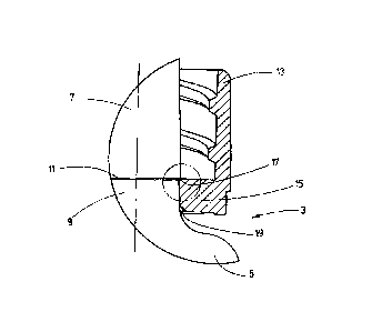
Fig. 1 shows a sectional view of a first embodiment of the syringe 1. A body
of the
syringe 3 is only visible in sections. The syringe comprises a syringe
cylinder 5 that is
followed by a distal end 7 which is designed as a syringe cone. Said end
comprises a
4
CA 02750665 2016-04-22
,
,
region 9 that is set back in a radial direction and that can be configured,
for example,
as a groove or a slot. In the depicted embodiment the distal end 7 is quasi
divided in
two resulting in a first region that is directed away from the syringe
cylinder 5 having
a diameter that increases ¨ seen in the direction toward the syringe cylinder
5 ¨
whereby this region comprises a tapered external surface, while a second
region that
is directed toward the syringe cylinder 5 has at the boundary between the two
regions a smaller diameter than the first region, thereby constituting the set-
back
region 9. This set-back region 9 is also configured as somewhat tapered in the
shown embodiment, and wherein the diameter ¨ seen in the direction toward the
syringe cylinder 5 ¨ increases. At the end that is directed toward the syringe
cylinder
5 the set-back region 9 transitions directly into the syringe cylinder 5. This
is why at
this location the diameter increases considerably.
The edge 11 is formed at the boundary between the region 9 that is set back in
a
radial direction and the first region which is where the diameter ¨ seen in
axial
direction ¨ changes in a jump-like fashion, and wherein the edge 11 extends
around
the distal end 7 of the syringe 1. Edge 11 comprises a chamfer that is not
visible in
Fig. 1. It is also possible for edge 11 to be configured as a ramp. In
particular, if the
body of the syringe 3 is comprised of glass it is not possible ¨ seen in a
longitudinal
section ¨ to envision an edge having an acute or right angle. Edge geometry of
this
kind would be associated with material stresses that would be too great. An
edge 11
with a chamfer and/or a ramp therefore results intuitively due to on the
manufacturing
process of the body of the syringe 3.
The syringe 1 comprises, furthermore, an attachment piece 13. Said attachment
piece comprises a clamping region 15 by which the holding forces are
introduced
into the region 9 of the syringe 1 that is set back in a radial direction. To
this end, in
a state when the attachment piece 13 is separate from the body of the syringe,
the
clamping region 15 has an inside diameter that is smaller than the smallest
outside
diameter of the region 9 that is set back in a radial direction. When the
attachment
piece 13 is placed onto the body of the syringe and positioned in such a way
that the
5
CA 02750665 2016-04-22
clamping region 15 engages with the region 9 that is set back in a radial
direction,
there results a dilatation of the clamping region 15, whereby elastic holding
forces
are introduced in the region 9 that is set back in a radial direction.
In the shown embodiment the attachment piece 13 is configured as a Luer lock.
Thus, it is used for providing a leak-proof and secure connection of further
injection
elements to the syringe 1. In other embodiments the attachment piece can be
configured as a closure element or as a connection element. If the attachment
piece
13 is configured as a closure element, its purpose is essentially to provide a
leak-
proof and secure closure of the syringe 1. To this end, it is possible to
integrate a
guarantee function in the closure element. If the attachment piece 13 is
configured
as a connection element, it serves as a coupler of the syringe 1 with further
injection
elements or as a vial adapter and/or to provide a coupling connection with a
vial
adapter. It is not necessarily required that the coupling action is provided
in the way
of a Luer lock connection element. Instead different connection elements
and/or
coupling elements can be used in different embodiments. The only essential
aspect
in this regard is that the attachment piece 13 be held in place on the body of
the
syringe 3 by a clamping region 15.
The clamping region 15 comprises a distal edge 17 and a proximal edge 19. In
known attachment pieces the distal edge 17 ¨ seen in a longitudinal section ¨
is
configured as having an acute angle or a right angle, whereby in the shown
position
of the attachment piece 13 on the body of the syringe 3 it is only possible
for the
distal edge 17 to establish a line-shaped contact with the edge 11 that is
configured
as chamfered and/or as a ramp.
It is clearly seen that the attachment piece 13 is held on the body of the
syringe 3 by
two mechanisms. On the one hand, there results a frictional grip between the
clamping region 15 and the set-back region 9 in which the clamping region 15
is
expanded resulting in elastic holding forces to be introduced into the set-
back region
9. On the other hand, there results a form closure in that the distal edge 17
engages
with the edge 11 of the region 9 that is set back.
6
CA 02750665 2016-04-22
If only a line-shaped contact exists between the distal edge 17 and the edge
11 that
is configured as chamfered and/or as a ramp, the holding force is not
optimally
supported at this location because only minimal frictional forces are present.
To the
contrary, the edge 17 may even slip off the chamfer or the ramp that is
constituted by
the edge 11 when forces are introduced into the attachment piece 13 in an
axial
direction and that are suitable for causing a separation of the attachment
piece 13
from the body of the syringe 3. Forces of this kind can occur, in particular,
when
preparing the syringe 1 for giving an injection, for example, when screwing
the
connection elements into the Luer lock of the shown embodiment, when emptying
the syringe 1 or also when separating the injection elements.
To increase the holding force of the attachment piece 13 on the body of the
syringe
3, the distal edge 17 of the clamping region 15 comprises a chamfer that is
not
visible in Fig. 1.
Fig. 2 shows an enlargement of the section that is seen in Fig. 1 and
highlighted by a
circle. Elements that are identical and that are functionally equal are
referenced by
the same reference symbols, which is why reference is being made here to the
preceding description. It can be seen that the edge 11 comprises a chamfer
that it is
configured in the present embodiment, in particular, as a ramp. Also visible
is the fact
that the distal edge 17 of the clamping region 15 comprises a chamfer.
Correspondingly, there results surface contact of the chamfers of edges 11,
17,
thereby creating increased friction which results in an overall improvement of
the
holding forces.
Fig. 3 shows another enlargement of a sectional view of the embodiment in Fig.
1.
Elements that are identical and that are functionally equal are referenced by
the
same reference symbols, which is why reference is being made here to the
preceding description. In this context, the observer sees even more clearly
than in
Fig. 2 that the edge 11 and the edge 17 both comprise a chamfer allowing them
to
engage by way of a surface-to-surface contact.
7
CA 02750665 2016-04-22
,
Fig. 4 shows an enlargement of the section that is highlighted by a circle in
Fig. 3.
Elements that are identical and that are functionally equal are referenced by
the
same reference symbols, which is why reference is being made here to the
preceding description. The clamping region 15 of the attachment piece 13 is
drawn
here at a certain distance relative to the set-back region 9 of the distal end
7 of the
syringe 1 in order to be able to emphasize the characteristics that have been
mentioned here even more clearly. In order to further optimize the friction
ratio
between the chamfered edges 11 and 17 the shown embodiment provides that the
edges are geometrically harmonized relative to each other. The edges
constitute
quasi complementary surfaces, thus providing for a large-surface contact area
and
thus increased friction.
In particular, in the shown embodiment it is envisioned that the chamfer of
edge 11,
on the one hand, and the chamfer of edge 17, on the other hand, enclose the
same
angle a with the longitudinal axis of the syringe 1. The result is an optimal
harmonization of the edges 11, 17 with each other in terms of their geometry,
thereby creating an especially secure contact action and thus especially high
friction.
In the embodiment that is shown in Figs. 1 to 4 the attachment piece 13 is
disposed
inside the set-back region 9 in a position that is maximally directed away
from the
syringe cylinder 5. The result is that the edges 11 and 17 come to lie
directly against
each other. Since the region that is set back 9 is configured as slightly
tapered, the
clamping region 15 is in contact with said region at an area having the
smallest
diameter, and wherein also the dilatation of the clamping region 15 takes ¨
seen
along the longitudinal axis of the syringe 1 ¨ its minimally possible value.
Fig. 5, on the other hand, shows an embodiment that has the attachment piece
13
disposed in a position this is ¨ seen along the longitudinal axis of the
syringe 1 ¨
arranged further toward the cylinder of the syringe 5. Elements that are
identical and
that are functionally equal are referenced by the same reference symbols,
which is
why reference is being made here to the preceding description.
8
CA 02750665 2016-04-22
The arrangement of the attachment piece 13 within the set-back region 9 is
also
referred to as the placement position. Different placement positions result
from the
attachment piece 13 being brought into pre-determined positions by the
machinery
assembling the syringe 1. With regard to its overall length, however, the body
of the
syringe has a tolerance that is not taken into account during the placement of
the
attachment piece 13. Correspondingly, for shorter syringes there results a
placement
position of the attachment piece 13 that is ¨ seen in axial direction ¨
directed away
further from the cylinder of the syringe 5 than can be gathered, for example,
from
Figs. 1 to 4, while so-called deeper placement positions result for longer
syringes in
which the attachment piece 13 is disposed in a position that is ¨ seen in
axial
direction ¨ directed further toward the syringe cylinder 5.
One problematic aspect herein is the taper of the set-back region 9. Since the
outside diameter of said region increases in the direction toward the syringe
cylinder
5, the clamping region 15 is dilated more in a deep placement position than in
a
higher-up placement position. In the case of a deep placement position this
results in
higher material stresses. In the most unfavorable event, the clamping region
15 may
thus be overstretched in the deep position resulting in a permanent relaxation
of the
material and considerably reduced friction and holding forces.
This is particularly problematic in cases when the syringe 1 is sterilized
with a pre-
positioned attachment piece 13. The temperature ranges that are typically
achieved
during this process are relatively close to the glass transitioning
temperature of the
material, which comprises the attachment piece 13 and/or of which the
attachment
piece consists. Permanent material changes of the attachment piece 13 can be
the
result of working in these temperature ranges, which causes material
relaxation and
a considerable decrease of the friction and holding forces.
To avoid this disadvantage, the clamping region in the shown embodiment has an
axial extension that is, in relation to half the axial extension of the set-
back region 9
at the distal end 7, almost of the same size. It is generally preferred that
the axial
extension of the clamping region 15 is smaller or of equal size in comparison
to half
9
CA 02750665 2016-04-22
the axial extension of the set-back region 9. Using the total length tolerance
of the
body of the syringe 3 as basis, it can be seen that even for the deepest
conceivable
placement positions of the clamping region 15, there occurs no extension into
a
region that is disposed ¨ seen in axial direction ¨ so closely in relation to
the syringe
cylinder 5 that would cause concerns with regard to an overexpansion and/or
relaxation of the clamping region 15. The axial extension of the clamping
region 15
which is reduced according to the invention results in the fact that,
independently of
the actual length of the body of the syringe 3, only a region of the set-back
region 9
is effectively used within the total length tolerance for the clamping action
of the
attachment piece 13 that is directed away from the syringe cylinder 5. This
way, the
expansion of the clamping region 15 is limited to acceptable values.
The shown embodiment additionally envisions that the proximal edge 19 of the
clamping region 15 comprises a chamfer. Preferably, this chamfer is configured
as
being relatively wide, thereby contributing to a further reduction of the
axial extension
of the region that engages in a clamping fashion with the set-back region 9.
Thus, in
particular with deep placement positions, the chamfer 19 has the effect that
the any
direct contact of the clamping region 15 in the region of the largest diameter
of the
set-back region 9 is avoided. Consequently, not only is any over-expansion of
the
clamping region 15 avoided but, simultaneously, it is achieved that the region
of the
clamping region that is directed away from the syringe cylinder 5 can make
contact
safely and securely against the set-back region 9. If the edge 19 were not
chamfered, the clamping region 15 would altogether be pre-expanded to the
diameter of the set-back region 9 that is in contact with it on the edge 19.
Any safe
contact of the region that is directed away from the syringe cylinder would no
longer
apply due to the taper of the set-back region 9.
In the shown embodiment the clamping region 15 comprises a chamfer on the
proximal edge 19 as well as a reduced axial extension. But an embodiment in
which
the clamping region 15 comprises a reduced axial extension while the edge 19
does
not comprise a chamfer is also conceivable. Also feasible is an embodiment in
which
CA 02750665 2016-04-22
the clamping region 15 has an axial extension that is larger than half the
axial
extension of the set-back region 9, while the proximal edge 19 comprises a
chamfer.
Fig. 6 shows the enlargement of the section from Fig. 5 that is marked therein
by a
circle. Elements that are identical and that are functionally equal are
referenced by
the same reference symbols, which is why reference is being made here to the
preceding description. In particular, Fig. 6 clearly shows that the proximal
edge 19 of
the clamping region 15 comprises a chamfer, thereby reducing ¨ seen in axial
direction ¨ the effective contact region between the clamping region 15 and
the set-
back region 9.
The holding forces of the attachment piece 13 on the body of the syringe 3 can
be
further optimized by providing an advantageous geometrical design of the
clamping
region 15.
Figs. 7 to 13 show different views, respectively, of different embodiments of
an
attachment piece 13 that are at an orthogonal orientation relative to the view
shown
in Figs. 1 to 6. The glance of the observer herein is directed along the
longitudinal
axis of the attachment piece 13. Elements that are identical and that are
functionally
equal are referenced by the same reference symbols, which is why reference is
being made here to the preceding description. Fig. 7 demonstrates that the
clamping
region 15 comprises a central recess 21 that receives in the assembled state
the set-
back region 9 of the distal end 7 of the syringe 1. In the embodiment as shown
in Fig.
7 the recess 21 has a hexagonal geometry, thereby creating six equivalent
contact
surfaces one of which is referenced in an exemplary manner by the reference
number 23. Thus, in the present instance the clamping region 15 is ¨ seen in a
top
view ¨ configured hexagonally. It is seen that a hexagonal shape of the
clamping
region is especially advantageous with regard to the holding forces that are
introduced in the region 9 that is set back in a radial direction. In
particular, based on
the increased holding forces, the hexagonal geometry of the clamping region 15
allows for a reduction of the axial extension of the clamping region 15,
whereby said
region can be smaller or of equal size in comparison with half the axial
extension of
11
CA 02750665 2016-04-22
the set-back region 9, while the associated loss of friction surface does not
have a
negative effect on the holding forces.
In the embodiment in Fig. 7, the corners at which two equivalent contact
surfaces 23
come to lie adjacent to each other are rounded.
Fig. 8 shows an embodiment that is very similar to the embodiment shown in
Fig. 7.
A difference is the fact that the corners of the contact surfaces 23 that lie
adjacent to
each other are not rounded. At any rate, there results a hexagonal clamping
region
that is ¨ seen in circumferential direction ¨ configured as continuous and
comprised six equivalent contact regions 23.
10 On the other hand, the clamping region 15 of the embodiment shown in
Fig. 9 ¨ seen
in circumferential direction ¨ is not configured as continuous but comprises
at least
one recess, thereby forming at least one clamping jaw. The concrete embodiment
that is shown comprises ¨ seen in circumferential direction ¨ six equivalent
recesses
that extend essentially radially so that six equivalent clamping jaws 27 are
formed.
15 The clamping jaws 27 surround the recess 21 that receives in the
assembled state
the set-back region 9 of the distal end 7 of the syringe 1. Each of the
clamping jaws
27 comprises an equivalent contact region 23 by which holding forces are
introduced
in the region 9 that is set back in radial direction 9 of the syringe 1. The
at least one
recess 25 in Fig. 9 has a long-extended form in radial direction and extends
from the
20 recess 21 to an outer edge 29 of the clamping region 15.
The embodiment according to Fig. 10 also comprises at least one recess 25; in
this
instance, specifically six equivalent recesses 25. This means, here too, the
result is
six equivalent clamping jaws 27. In contrast to the embodiment in Fig. 9,
however,
the recesses 25 do not extend in radial direction from the recess 21 all the
way to the
25 outer edge 29 of the clamping region 15 but only to about half of this
distance. The
clamping region 15 thus comprises ¨ seen in circumferential direction ¨ a
continuous
area that ¨ seen in radial direction ¨ is directed toward the outer periphery
29. By
varying the radial extension of the at least one recess 25 it is possible to
adjust the
springy elasticity of the individual clamping jaws 27. If the recesses 25
extend ¨ as
12
CA 02750665 2016-04-22
shown in Fig. 9 ¨ over the entire radial expansion of the clamping region 15,
the
clamping jaws 27 demonstrate high springy elasticity. The less the distance
that the
recesses 25 extend away from the recess 21 in the direction of the outer
periphery
29 of the clamping region 15, the lower is the springy elasticity of the
individual
clamping jaws 27. This way, using a variation of the radial extension of the
recesses
25, it is also possible to achieve a change of the holding forces that are
introduced in
the set-back region 9. The holding forces can also be pre-determined by the
width of
the recesses 25: the wider the recesses, the more the holding forces decrease.
It is
also possible to specifically select the contour of the recesses, which in the
present
instance increase from the inside to the outside: the wider the recesses are
radially
on the outside, the lower the holding forces.
The recesses 25 in Fig. 11 ¨ seen in a top view ¨ have a quasi drop-shaped
form.
This provides the clamping jaws 27 with edges 31 that are positioned
perpendicularly
relative to the contact surfaces 23. In the outer area of the clamping region
15 this
results in an ¨ seen in circumferential direction ¨ increased distance between
individual clamping jaws 27. In this embodiment as well, the radial extension
of the
recesses 25 does not reach completely to the outer periphery 29. The springy
elasticity of the clamping jaws 27 can be varied by an interaction of the
shape of the
recess 25, as seen in a top view, and its radial extension. If the recesses 25
¨ as
presently shown ¨ are configured, for example, as drop-shaped, and wherein
this
results ¨ seen in circumferential direction ¨ in an enlarged distance of the
individual
clamping jaws 27 relative to each other, the consequence is an increased
springy
elasticity of the clamping jaws 27. The shape and radial extension of the
recesses 25
can thus be adjusted with each other in order to achieve a desired springy
elasticity
of the clamping jaws 27, and thereby a desired value of the holding forces
that are
introduced in the set-back region 9.
In Fig. 12 the recesses 25 ¨ shown in a top view ¨ are also configured as drop-
shaped. But their radial extension reaches from the recess 21 all the way to
the outer
periphery 29 of the clamping region 15. But in contrast to the previous
embodiments,
13
CA 02750665 2016-04-22
the contact regions 23 are not configured as flat; instead they are curved
resulting in
the formation of cylinder section areas. In this way, the recess 21
¨ seen in a top view ¨ is not delimited by a hexagon but by a circle.
Preferably, the
curvature of the cylinder-section-shaped contact regions 23 follows the
curvature of
the set-back region 9 resulting in the shown embodiment in an especially large-
surface contact between the contact regions 23 and the set-back region 9. This
in
turn results in stronger holding forces.
Fig. 13 shows an embodiment of a geometrical configuration of a clamping
region
that comprises only four recesses 25. The recesses 25 have a ¨ seen in
circumferential direction ¨ oblong, oval shape, and wherein they comprise
apertures
that are disposed symmetrically relative to the short axis of the oval in the
direction of
the recess 21, thereby constituting four clamping jaws 27. The contact regions
23 in
turn are curved in cylinder-section-shape resulting in the recess 21 ¨ seen in
a top
view ¨ being delimited by a circle. The ¨ seen in circumferential direction ¨
oblong,
oval shape of the recesses 25 results in conjunction with the apertures
undercuts
being formed behind the clamping jaws 27, thereby increasing their elasticity.
Simultaneously, the contact regions 23 can be relatively large in this way,
whereby a
considerable part of the available cylinder area is used for introducing
holding forces
in the set-back region 9. In this embodiment as well, in the radial direction,
the
recesses 25 do not extend completely from the recess 21 to the outer periphery
29.
But the essential aspect of the shown embodiment is the fact that due to the
special
geometry of the recesses 25, which are oblong in the circumferential
direction, a high
level of elasticity of the clamping jaws 27 accompanied, simultaneously, by
large
contact regions 23 is possible.
It is understood that in order to obtain a syringe 1 according to the
invention each of
the geometries of the clamping regions illustrated in Figs. 7 to 13 can be
combined in
any way with the other characteristics that have been described in connection
with
Figs. 1 to 6.
14
CA 02750665 2016-04-22
Overall, it can be seen that the present invention provides stronger holding
forces
between the attachment piece 13 and a body of a syringe 3, thereby preventing
these elements from becoming inadvertently separated, in particular, during
the
preparation of an injection. Simultaneously, the present invention avoids the
disadvantage that a deep placement position of the attachment piece 13 on the
body
of the syringe 3 may result in stressing or overexpansion of the clamping
region 15,
thereby losing the holding forces. Moreover, the disadvantage of a relaxation
of
material of the attachment piece 13 connected to the body of the syringe 3
during
sterilization and accompanied by a loss of the holding forces is avoided.