Note: Descriptions are shown in the official language in which they were submitted.
CA 02751078 2011-07-28
WO 2010/086668 PCT/GB2010/050147
1
Improvements relating to Frames and Hinges
The present invention in one aspect relates to frames for
shelters, their construction, assembly and use, and methods
thereof. In particular, though not exclusively, the invention
may relate to collapsible frames for shelters such as tents.
The present invention in another aspect relates to hinges,
their construction, assembly and use, and methods thereof. In
particular, though not exclusively, the invention may relate to
hinges for articulated joints between components of assemblies
such as frames (e.g., for collapsible frames, tent frames etc),
scaffolds or other equipment.
Shelters may be required for rapid deployment and removal in
emergency situations and/or for temporary use. Examples include
emergency decontamination stations, medical stations and/or
forensic stations. In each case, a sheltered environment or
temporary dwelling may be required where none otherwise exists.
Large inflatable tents are available for this purpose in order
to enable a rapid and simple deployment and provision of a
relatively large shelter. However, such inflatable tents are
complex and expensive in construction, prone to ruptures or
punctures and require the use of a powered pump for inflation.
The volume of material required to provide inflatable parts of
the tent also greatly increase the bulk and weight of the tent
when deflated and stored.
The invention in one aspect at least, aims to provide means
which may be used to address these matters. An alternative
rapidly deployable shelter structure is provided.
Hinges for connecting together components of an articulated
assembly come in many forms. The majority are simple in
structure and comprise an axle or pivot bearing member about
which hinge limbs are separately joined substantially in
CA 02751078 2011-07-28
WO 2010/086668 PCT/GB2010/050147
2
isolation of each other. An example is a hinge pin around
different sections of the length of which are parts of each of
two hinge limbs disposed to rotatably clasp the pin along
sections of its length.
On the one hand, this simplicity typically prohibits provision
within the structure of the hinge of means for locking such a
hinge in a desired state of splay/configuration. Such locking
may often only be achieved by provision of additional locking
or securing means external to a hinge.
On the other hand, while the clasping, by hinge limbs, of
lengths of the hinge pin may provide some degree of strength in
the hinge against forces transverse to the pin, this is at the
expense of having to provide a long pin - the greater the
length of pin clasped by a hinge limb, the greater the lateral
strength the of the hinge.
In articulated frames, such as collapsible frames for shelters,
both of these consequences may be undesirable in terms of the
inability to safely lock the articulated frame in a desired
configuration, or the volume occupied by elongated hinges
providing articulation with suitable strength.
The invention in one aspect at least, aims to provide means
which may be used to address these matters. An alternative
hinge structure is provided.
In a first of its aspects, the invention provides a collapsible
frame for a shelter including members articulated by a pivot
(e.g. hinge) comprising a pair of opposed pivot members (e.g.
plates) joined at a common axle about which a surface of a
first pivot member of the pair is slidingly rotatable over a
surface of a second pivot member of the pair in parallel
opposition thereto. Thus, opposed parallel surfaces (e.g.
plate surfaces) of the pivot members may slide against each
CA 02751078 2011-07-28
WO 2010/086668 PCT/GB2010/050147
3
other by action of the pivot to provide lateral strength in a
laterally compact form.
In a second of its aspects, the invention may provide a (e.g.
one-piece) collapsible shelter frame comprising two or more
beam assemblies each including at least two beam members joined
at a pivot (e.g. hinge) means and reversibly pivotable thereat
to a relatively splayed position collectively to form an arch,
wherein at least two said beam assemblies are joined by cross-
brace means slideably coupled thereto to reversibly expand
therebetween to separate the joined beam assemblies permitting
concertina-like expansion and collapse of the shelter frame.
Accordingly, not only a concertina collapsibility of arched is
provided, but also a folding collapse of arches thereafter.
This enables rapid collapse or assembly of the frame from a
compact collapsed/storage state. Sliding coupling of the cross-
brace means to each of the two beam assemblies it joins,
enables a smooth and quick concertina action therebetween. The
pivot (e.g. hinge) means preferably comprised a pair of opposed
plates joined at a common axle about which a face of one plate
of the pair is slidingly rotatable over a face of the other
plate of the pair in parallel opposition thereto. A pivot means
of the shelter frame may be according to the invention in its
first or third aspect. A beam member of a beam assembly may be
connected to one plate of the pair and another beam member of
the beam assembly may be connected to the other plate of the
pair. Providing a pivot means using opposed facing plates in
this way strengthens the pivot means against transverse forces
and torques by enabling such influences to be spread over the
opposing plate areas. It also provides a laterally compact
form.
A face of one plate of the pair of plates may include one or
more lug parts extending therefrom and/or disposed thereupon to
extend into an arcuate (e.g. circular) channel (e.g. slot)
formed across the opposing face of the other plate of the pair
CA 02751078 2011-07-28
WO 2010/086668 PCT/GB2010/050147
4
of plates, the lug part being slideable along the arcuate
channel from one end of the channel to another end thereof by
action of relative rotation of the opposed plates. The channel
may be dimensioned such that the lug part abuts or engages one
end of the channel when the pivot means is in a fully
splayed/opened state, and/or such that the lug part abuts or
engages the other end of the channel when the pivot means is in
the closed state. A second such lug and corresponding arcuate
(e.g. circular) channel (e.g. slot) may be formed in the
opposed plates. Two such lugs may be formed to extend from the
same face of a common plate at locations there upon
diametrically opposed across the common axle. Two such
channels may be formed in the same face of a common plate such
that an end (e.g. each end) of any one of the two channels is
diametrically opposed across the common axle from an end of the
other of the two channels.
An aforesaid lug preferably projects outwardly of a plate
surface in a direction parallel to the axis of the common axle.
An opposed corresponding channel (e.g. slot) may have a depth
dimension which extends into the surface of a plate in a
direction parallel to the axis of the common axle.
The cross-brace means may include one or more pairs of crossed
arms wherein one arm of a pair is coupled to a said beam
assembly to permit sliding movement thereof along the beam
assembly and the other arm of the pair is fixed (e.g. in
position) to the beam assembly, and/or may be coupled thereto
at a fixed location. The other arm of the pair may be pivotably
so fixed to the beam assembly in this way. As a result of
fixing the location at which one crossed arm couples to a beam
assembly, a sliding movement of the location at which the other
crossed arm couples to the same beam assembly urges a
displacement of the location, relative to the beam assembly,
at which the crossed arms cross. This preferably urges an
CA 02751078 2011-07-28
WO 2010/086668 PCT/GB2010/050147
expansion or contraction of the cross-brace. Most preferably,
one, some or all crossed arms of a cross-brace means are rigid.
The cross-brace means may comprise a pair of crossed arms
5 pivotably joined where they cross to permit a scissor action
enabling said reversible expansion of the cross-brace means.
The cross-brace means may include a second said pair of crossed
arms pivotably joined where they cross, and each arm of any one
pair of crossed arms is pivotably joined to an arm of the other
pair of crossed arms. Accordingly, an expansion or contraction
of one pair of crossed arms may urge corresponding effects in
the other pair of crossed arms.
The cross-brace means may be operable to maintain an expanded
state to permit the relative positions of beam assemblies
separated thereby to be maintained thereby to permit arches
formed by the joined beam assemblies to stand upright in
tandem.
The cross-brace means may include locking means (e.g. brace
locking means) arranged to releasibly fix the location(s) upon
a said beam assembly at which the cross-brace means couples
thereto when the cross-brace means is in an expanded state. The
locking means may comprise a catch, latch, hook, belt, strap,
cable or other retaining means arranged to enable a part of the
cross-brace means slidingly coupled to a beam assembly to
fixedly couple or attach thereto at a desired location which
maintains the expanded state of the cross-brace means.
The locking means may include stop means arranged to prevent
sliding movement of the one arm of the pair therebeyond along a
beam assembly towards the location at which the other arm of
the pair is fixed to the beam assembly, and retaining means
operable to retain the one arm at the stop means. In this way,
the location upon a beam assembly at which a part of the cross-
CA 02751078 2011-07-28
WO 2010/086668 PCT/GB2010/050147
6
brace means slidingly couples thereto, may be jammed wedged or
otherwise held against a part of the beam assembly it is
coupled to.
Each one of the at least two beam members may comprise two beam
member portions joined at a pivot means together collectively
defining an articulated beam member. The articulated beam
member may have an upper beam member portion uppermost in use,
and a lower beam member portion lowermost in use, joined to the
upper beam member portion by a pivot means (e.g. a hinge). The
upper beam member portion may be a roof beam member portion for
the frame when erected. The lower beam member portion may be a
wall beam member portion forming a wall member portion of the
frame when erected. The upper and lower beam member portions
may be joined by a hinge arranged to reversibly splay the
joined beam member portions from a closed state of parallel
adjacency to a maximally splayed state disposing the upper and
lower beam member portions at a selected angle of splay (e.g.
exceeding 90 degrees). Upper beam member portions of two
pivotably joined articulated beam member portions of a beam
assembly may be joined by a hinge arranged to reversibly splay
the joined upper beam member portions from a closed state of
parallel adjacency to a maximally splayed state disposing the
upper beam member portions at a selected angle of splay (e.g.
exceeding 90 degrees).
Beam members or beam member portions may be joined at a pivot
means arranged to reversibly splay the beam members (or
portions) from a position of parallel adjacency to a relatively
splayed position.
Beam members may be joined at a pivot means arranged to
reversibly splay the beam members to a state of fixed splay
angle.
CA 02751078 2011-07-28
WO 2010/086668 PCT/GB2010/050147
7
The cross-brace means may join adjacent equivalent beams of
adjacent articulated beam assemblies which are lowermost in use
of the frame (e.g. wall beams) . Alternatively, the cross-brace
means may join adjacent equivalent beams of adjacent
articulated beam assemblies which are upper in use of the frame
(e.g. roof beams).
The one-piece collapsible shelter frame may further comprise
three separate beam assemblies two of which are separately
coupled via a respective one of two said cross-brace means to a
common intermediate beam assembly therebetween, wherein the
respective cross-brace means couple to the intermediate beam
assembly at a common slideable coupling means such that
expansion/collapse of one cross-brace means urges the same in
the other.
Cross-brace means may be slideably coupled to a beam assembly
via a slideable coupling disposed within in a longitudinal
channel or slot extending along a beam assembly and arranged to
slide therealong in response to expansion/collapse of the
cross-brace means.
Beam assemblies may be joined at an apex of the frame in use,
by a pair of collapsible top-braces articulated at a joint
between ends thereof.
The top braces may be joined by a tensioning means operable to
urge the opposed joints together to abut each other at their
articulated joints.
In a third of its aspects, the invention may provide pivot
(e.g. hinge) means comprising a pair of opposed plates joined
at a common axle about which a face of one plate of the pair is
slidingly rotatable over a face of the other plate of the pair
in parallel opposition thereto. A pivot means of the shelter
frame according to the invention in its first or second aspect
CA 02751078 2011-07-28
WO 2010/086668 PCT/GB2010/050147
8
may be according to the invention in its third or fifth aspect.
A beam member of a beam assembly may be connected to one plate
of the pair and another beam member of the beam assembly may be
connected to the other plate of the pair. Providing a pivot
means using opposed facing plates in this way strengthens the
pivot means against transverse forces and torques by enabling
such influences to be spread over the opposing plate areas.
Each of the pair of opposed plates may be rotatably coupled
upon the common axle via a threading disposed thereupon to
engage with a reciprocal threading upon the common axle such
that sliding rotation of one plate face over another plate face
of the pair results in a relative displacement between the
plates along the axis of the common axle. This may be a
progressive displacement in a manner analogous to that of a
threaded nut along the shaft of a threaded bolt. The opposed
plates may be arranged such that relative rotation thereof to
open the pivot means displaces the plates to urge the opposed
faces together, such as progressively towards (and ultimately
into) contact between opposed faces when the pivot means is
maximally splayed/open. A frictional or interference fit may
be achieved in this state of interface.
A face of one plate of the pair of plates may possess one or
more lug parts extending therefrom and disposed thereupon to
extend into an arcuate (e.g. circular) channel formed across
the opposing face of the other plate of the pair of plates, the
lug part being slideable along the arcuate channel from one end
of the channel to another end thereof by action of relative
rotation of the opposed plates. The channel may be dimensioned
such that the lug part abuts or engages one end of the channel
when the pivot means is in a fully splayed/opened state, and/or
such that the lug part abuts or engages the other end of the
channel when the pivot means is in the closed state. A second
such lug and corresponding arcuate (e.g. circular) channel may
be formed in the opposed plates. Two such lugs may be formed
CA 02751078 2011-07-28
WO 2010/086668 PCT/GB2010/050147
9
to extend from the same face of a common plate at locations
there upon diametrically opposed across the common axle. Two
such channels may be formed in the same face of a common plate
such that an end (e.g. each end) of any one of the two channels
is diametrically opposed across the common axle from an end of
the other of the two channels.
An aforesaid lug preferably projects outwardly of a plate
surface in a direction parallel to the axis of the common axle.
An opposed corresponding channel may have a depth dimension
which extends into the surface of a plate in a direction
parallel to the axis of the common axle.
One plate of the pair may possess a through-opening extending
through the plate to the face thereof, and the other plate of
the pair may have an orifice (which may be a through-opening
extending through the plate to the face thereof) disposed in
the opposing face thereof to be positionable in register with
the through-opening by rotation of one or both plates about
their common axle. The pivot means may include a pin
insertable into the through-opening and dimensioned to extend
along the through-opening and into the orifice when the
through-opening and orifice are in register. When the orifice
is a through opening, the pin may be dimensioned to extent
through both through (and optionally beyond) openings in
register. The two through openings may be disposed in the
opposing plates to be positionable in register when the pivot
is in a fully splayed/opened state. A pin may be placeable to
extend simultaneously along the through openings when so
registered thereby to lock the plates in the fully splayed
state.
The through-opening is preferably accessible in use of the
pivot means. When used as the pivot means of a beam assembly
of the frame, the through-opening is accessible at any relative
orientation of beam members joined by the pivot means.
CA 02751078 2011-07-28
WO 2010/086668 PCT/GB2010/050147
The pin may be extractably insertable into the through-opening
and concurrently into the orifice when in register. The pin
may have a moveable shaft part moveable relative to the body of
5 the pin along a long axis thereof along the through opening and
into the orifice when in register.
The body of the pin may comprise a sleeve part through which an
axial bore extends within which the shaft part is slidingly
10 moveable. The shaft and sleeve parts may be structured and
arranged to retain the shaft part within the sleeve part.
The moveable shaft part may be moveable along the bore between
a retracted state in which the shaft part does not extend from
the sleeve part via an end of the bore, and a projecting state
in which the shaft part projects from the sleeve part via an
end of the bore. In the projecting state, the shaft part is
preferably dimensioned to project from the sleeve part into an
orifice of a said plate of the pivot means when in register
with a through-opening in an opposing said plate within which
the sleeve part is housed but does not project (e.g. does not
project into the through-opening when in register). When the
through-opening and orifice are not in register, the shaft
portion is preferably arranged to adopt the retracted state.
The opposing faces of the plates of the pivot means are
preferably disposed such that the opposing face of the plate
containing the orifice covers the end of the through-opening
via which the shaft part is moveable to project into the
orifice when in register therewith. This covering may maintain
the shaft in one pate in the retracted state until in register
with the orifice in the opposing plate. The plates of the
pivot means may thus be slidingly rotatable about their common
axle when the shaft of the pin is retracted, and locked in
relative position by the pin when brought into register.
CA 02751078 2011-07-28
WO 2010/086668 PCT/GB2010/050147
11
Preferably the pivot means, e.g. when a pivot means of a beam
assembly such as the frame of an aspect of the invention,
achieves a maximally splayed/opened state of beam members
joined thereby when the through-opening and orifice or
respective opposed plate faces are in register.
The moveable shaft part of the pin may include a hand-operable
head part turnable by hand to turn the shaft part about its
axis within the bore of the sleeve part. The sleeve part may
have an end part nearmost the head part of the shaft shaped to
engage with the head part when the shaft part is in a
projecting state, and to disengage from the head part when the
shaft part is in a retracted state. Accordingly, in the
engaged state the moveable shaft is preferably turnable only if
the sleeve part is so turnable, while in the disengaged state
the shaft part is turnable independently of the sleeve part.
The head part of the shaft may possess a projecting part
disposed to be reversibly moveable, by movement of the head
part relative to the sleeve part, from a first position in
which it engages a recess part of the sleeve part when the
shaft part is in the projecting state, to a second position in
which it engages parts of the sleeve part adjacent the recessed
part thereof to retain the shaft part in the retracted state.
A pull and turn action upon the head of the shaft part may
effect this movement from the projecting state to a maintained
state of retraction.
The head part and sleeve part of the pin may possess
reciprocally-shaped opposable parts dimensioned to intermesh
when engaged such that the shaft part becomes turnable about
its axis by turning the head part. Reciprocally-shaped
opposable parts include recesses dimensioned to receive
opposable projections. This enables the pin as a whole to be
turned in unison about its axis when the shaft part is
projecting into an orifice of a plate from a through-opening of
CA 02751078 2011-07-28
WO 2010/086668 PCT/GB2010/050147
12
an opposed plate containing the sleeve part of the pin. As
such, the sleeve part may be externally threaded with a thread
arranged to engage a reciprocal threading disposed on the walls
of the bore of the through-opening containing it. This enables
the pin, with projecting shaft part, to be screwed down along
the bore of the through-opening to urge until stopped by the
opposing plate containing the orifice in register.
The moveable shaft part may be spring-loaded within the sleeve
part so as to be urged in to a quiescent state of projection
therefrom. The bore of the sleeve part may separated by a
spring from and opposed abutment surface of the moveable shaft
part such that retraction of the shaft into the bore compresses
the spring.
The pivot means may possess two such pins as described above,
each being associated with a respective through-opening in one
plate of the pivot means, and a corresponding orifice in the
opposed plate thereof. The through-openings and corresponding
orifices may be disposed in a respective plate at opposite
sides of the common axle.
In a fourth of its aspects, the invention may provide a one-
piece collapsible frame comprising a shelter frame described
above. The invention may comprise a one-piece collapsible tent
frame and a may include a covering adapted to fit intimately
over the collapsible tent frame when fully expanded thereby to
provide a tent. The covering may be adapted to attach to the
frame to depend from and under arches of the frame when fully
expanded thereby to provide a tent.
Some or all pivot means, and/or beam members may be formed from
a metal, such as Aluminium, or a plastic or fibre glass.
It is to be understood that the above describe realisations of
equivalent methods of erecting a frame for a shelter or a
CA 02751078 2011-07-28
WO 2010/086668 PCT/GB2010/050147
13
shelter (e.g. tent) including such a frame. The invention, in
yet further aspects, provides such equivalent methods as would
be readily apparent to the skilled person from the foregoing.
In a fifth of its aspects, the invention may provide a lockable
hinge including: a pair of opposed hinge members (e.g. opposed
plates such as flat plates) connected at a common axle about
which a face or surface of a first hinge member of the pair is
by operation of the hinge slidingly rotatable over a face or
surface of a second hinge member of the pair in parallel
opposition thereto; lock means operable to move a locking
member by a movement substantially parallel to a said surface
reversibly into a position which obstructs said sliding
rotation of one of the pair of hinge members relative to the
other of the pair hinge members from a position which does not
so obstruct thereby reversibly to lock the hinge. Either or
each of the first and second hinge members may be so slidingly
rotatable relative to each other. The opposed surfaces
preferably are in contact (e.g. sliding contact), preferably
all opposed parts of said opposed surfaces are in contact.
In a sixth of its aspects the invention may provide a
collapsible frame for a shelter, such as according to the
invention in its first, second or fourth aspect, including
members articulated by a lockable hinge described herein (e.g.
the invention in its fifth aspect).
Provision of opposed sliding surfaces desirably imbues the
hinge with strength against forces transverse to the axle of
the hinge without requiring an axially elongated hinge
structure. Using opposed facing surfaces (e.g. flat surfaces,
or plates, or disks etc) in this way strengthens the hinge
means by enabling such influences to be spread over the
opposing plate areas. The opposed surfaces preferably extend in
a direction transverse to the common axle and may extend a
distance greater than the length of the common axle. Use of
CA 02751078 2011-07-28
WO 2010/086668 PCT/GB2010/050147
14
extended and opposed sliding surfaces permits a simple lock
structure which may, for example also operate by sliding the
locking member to and from the position of obstruction. The
lock means may be operable to rotate the locking member into
said obstructing position. The rotation of the locking member
may be about an axis transverse to the opposed sliding surfaces
of the hinge members such that parts of the locking member may
revolve about that axis to and from the obstructing/locking
position.
The locking member may include a cam mounted upon a rotatable
cam shaft. The cam shaft may be operable reversibly to rotate
the cam such that an eccentric portion of the cam is positioned
to obstruct said sliding rotation thereby reversibly to lock
the hinge. The cam may provide an eccentric portion shaped
substantially as (or to incorporate) a circular segment. The
circular segment may have a distal peripheral edge defined by a
constant maximal radius centred upon the cam shaft. The cam may
define elsewhere a peripheral edge closer to the cam shaft. The
cam may be dimensioned such that when no part of the distal
peripheral edge obstructs sliding rotation of the hinge
members, then nor does any other part of the peripheral edge of
the cam. In alternative embodiments the lock means may be
operable to move the locking member by a linear movement
reversibly into the obstructing position. For example, the lock
member may be a rod, block or bolt (arranged on one hinge
member) operable to be slid into a slot, opening, orifice
arranged on the other hinge member.
The lock member may be attached to one of the hinge members of
the pair adjacent an edge of the other of the hinge members
which edge presents a locking recess in which said edge is
closer to the common axle than are parts of said edge
immediately adjacent the locking recess and is shaped and
adapted to admit the locking member to lock the hinge. The
locking recess may reciprocate or be complementary to the shape
CA 02751078 2011-07-28
WO 2010/086668 PCT/GB2010/050147
of those parts of the locking means it is adapted to admit,
preferably intimately.
The lock member may be attached to one of the hinge members of
5 the pair adjacent an edge of the other of the hinge members
which edge presents a locking recess in which said edge is
further from the common axle than are parts of said edge
immediately adjacent the locking recess and is shaped and
adapted to admit the locking member to lock the hinge. The
10 locking recess may be disposed to be positionable between the
locking member and the common axle, or the locking member may
be disposed to be positionable by between the common axle and
the locking recess, when the locking recess is positioned (by
relative rotation of the sliding surfaces) to admit the locking
15 member.
The hinge member comprising the locking recess may include a
plurality of separate such locking recesses spaced about said
edge to permit the locking of the hinge in any one of a
respective plurality of hinge configurations.
The locking member (e.g. when a bolt) may be linearly slidable
towards/from the common axle or generally towards the centre of
the plate or hinge part containing the locking recess.
Alternatively, the locking member may be arranged to slide
transversely to the radial direction as from the common axle
and reversibly to abut a surface of the locking recess forming
a chord at a circular peripheral edge of a hinge member (e.g.
rotatable plate) of the pair. This permits linear movement of a
locking member on one hinge member to obstruct rotational
movement of an opposing hinge member.
The hinge member comprising the locking recess may be rotatable
to revolve the edge defining the recess about the common axle
reversibly to draw the locking recess into register with the
locking member to permit the locking recess to admit the
CA 02751078 2011-07-28
WO 2010/086668 PCT/GB2010/050147
16
locking member. For example, the locking recess may be formed
in a (e.g. an edge part) part of one of the hinge members
comprising the slidable surface thereof (e.g. formed by-in the
edge bounding the slidable surface) and may be positionable
adjacent a locking member arranged at an adjacent part of the
other hinge member to permit admission of the locking member
into the recess as desired. Alternatively, for example, the
locking member may be attached to a part of one of the hinge
members comprising the slidable surface thereof and may be
positionable adjacent a locking recess arranged in an adjacent
part of the other hinge member for admission into the recess as
desired.
One or each hinge member may comprise a flat plate or disk part
comprising a sliding opposed surface/face as described above.
The outer peripheral edge of such plate/disk of such a hinge
member may be shaped to define the locking recess. The edge
may define a plurality of locking recesses spaced along the
edge of each positionable in register with the locking member
by rotating the hinge member to a respective different
configuration or relative position.
The locking recess and those parts of the locking member to be
admitted into the locking recess may be complementarily shaped.
The may be arranged such that the locking member is
positionable to substantially fully occupy the locking recess.
For example, the parts of the locking member adapted to be
positionable within the locking recess may have an outermost
edge or surface which at least in part has a constant radius of
curvature. This may define an eccentric portion of the locking
member in the manner of a cam. The locking recess may present a
concave recess edge having a radius of curvature centred on the
same point of curvature and preferably having the same (or
marginally larger) radius as the eccentric. The angular extent
of the eccentric may be equal to or greater than the angular
extent of the correspondingly shaped locking recess. This
CA 02751078 2011-07-28
WO 2010/086668 PCT/GB2010/050147
17
enables the eccentric to fill the locking recess in use. The
benefit is increased locking strength and rigidity and the
ability to excavate unwanted accumulated debris/dirt from
within the locking recess by a scooping of pushing action of
the locking member as it is rotated into the locking recess. In
alternative embodiments the convex cam eccentric may simply be
slideable in and out of the concave locking recess by a linear
sliding movement e.g. radial to the common axle. In this
example, the cam need not be rotatable. Alternatively the
locking recess may be a linear slot (e.g. radial to the common
axle) and the locking member a bolt, rod or elongate block
dimensioned to removably fill the slot.
Opposed edges of the pair of hinge members may collectively
define a discharge conduit extending from a discharge inlet
opening immediately adjacent the locking recess to a discharge
outlet opening at the periphery of the hinge and adapted to
conduct debris urged therein from the locking recess by action
of rotation of the locking member into the locking recess and
towards the discharge inlet. In this way, turning the locking
member into the locking recess serves to push unwanted debris
out of the locking recess and into a dedicated conduit along
and out of the exit end of which the debris may be pushed
either by subsequent debris forced in behind it by further use
of the locking member, or by future relative rotation of the
hinge members which provide the opposing edges defining the
conduit. That us to say, the opposing edges defining the
conduit are preferably relatively moveable in opposite senses
by rotation of one hinge member relative to the other. This
assists is evacuating the conduit of debris which might
otherwise jam the hinge. It has been found that provision of a
rotating lock means and a hinge with slidingly rotatable
opposing surfaces is particularly effective in enabling such a
cleaning mechanism.
CA 02751078 2011-07-28
WO 2010/086668 PCT/GB2010/050147
18
The lock means may include a rotation stop means arranged
relative to the locking member to prevent continued rotation
thereof beyond a position in which the locking member does not
obstruct relative rotation of said hinge members. This enables
a user to determine when the locking member is cleared of the
locking recess and the hinge in an unlocked state. The lock
means may include a rotation stop means arranged relative to
the locking member to prevent continued rotation thereof beyond
a position in which the locking member obstructs e.g. fully
obstructs, relative rotation of said hinge members. This
enables a user to determine when the locking member fully
occupies, or is fully within, the locking recess and the hinge
in a locked state.
The lock means may include a locking surface against which a
surface of the locking member is moveable into a frictional
interference fit by action of rotation of the locking member to
releasibly retain the locking member. The interference fit may
be achieved by rotation of the locking member into a position
which obstructs said sliding rotation (e.g. the hinge locked)
thereby to releasibly retain the locking member so positioned
and/or may be achieved by rotation of the locking member into a
position which does not obstruct said sliding rotation (e.g.
the hinge unlocked) thereby to releasibly retain the locking
member so positioned. The locking surface may be provided by a
concave surface part of the locking recess. The peripheral
edge of the locking member (e.g. the edge of the eccentric of a
cam) may be shaped with a radius of convex curvature which
increases at parts of the locking member which trail when the
locking member is rotated to the locking position so as to be
brought into a frictional interface with the concave surface of
the locking recess over which parts of the locking member of
lesser radius otherwise freely pass. The parts of the locking
member with increased radius may be disposed upon the locking
member at parts thereof which are rotatable into the locking
recess only after the locking recess has been filled by the
CA 02751078 2011-07-28
WO 2010/086668 PCT/GB2010/050147
19
preceding parts of the locking member. Those parts may then
serve to wedge the locking member into the locking recess fully
occupied.
One or each of the first and second hinge members may include a
plate portion providing a respective one of the two said
parallel opposed surfaces.
The lockable hinge may include a third hinge member comprising
a plate portion connected to the second hinge member at said
common axle about which a surface of the third hinge member is
by operation of the hinge slidingly rotatable over another
surface of the second hinge member in parallel opposition
thereto such that the plate portion of the second hinge member
is sandwiched between the plate portions of the third and first
hinge members which are slidingly rotatable thereover in
unison. The first and third hinge portions may be fixed
together. In this way a laminate structure may be provided
comprising four opposing slidable surfaces, two of which are
opposite sides of a middle plate sandwiched between two outer
plates. The two outer plates may be joined so as to rotate
together in tandem/unison. This provides additional lateral
strength to the hinge.
The lockable hinge may include a fourth hinge member comprising
a plate portion connected to the first hinge member at said
common axle about which a surface of the fourth hinge member is
by operation of the hinge slidingly rotatable over another
surface of the first hinge member in parallel opposition
thereto such that the plate portion of the first hinge member
is sandwiched between the plate portions of the fourth and
second hinge members which are slidingly rotatable thereover in
unison. The second and fourth hinge portions may be fixed
together. In this way a laminate structure may be provided
comprising six opposing slidable surfaces, two of which are
opposite sides of a first intermediate plate sandwiched between
CA 02751078 2011-07-28
WO 2010/086668 PCT/GB2010/050147
a first outer plate and a second intermediate plate, and
another two of which are opposite sides of the second
intermediate plate sandwiched between the first intermediate
plate and a second outer plate. The locking member may be
5 attached to one plate of a laminate and the locking recess
formed in the edge of an opposing other pate of the laminate.
A surface of one said hinge member may include one or more lug
parts extending therefrom and disposed thereupon to extend into
10 a respective one of one or more arcuate channels formed across
an opposing surface of another said hinge member. An arcuate
channel(s) may be formed in the first hinge member and a lug
part(s) may be formed on the second hinge member. The hinge
member containing the locking recess may also contain the
15 arcuate channel(s). When three hinge members are employed in
the hinge, e.g. as described above, an intermediate hinge
member or plate may contain the arcuate channel(s) and an outer
hinge member/plate may contain the lug part(s).
20 When four hinge members/plates are employed in the hinge, e.g.
as described above, a first outer hinge member/plate may
contain the lug part(s), an adjacent first intermediate hinge
member/plate may contain the arcuate channel(s)and the locking
member, a second intermediate hinge member/plate adjacent the
first intermadiate hinge member may contain the locking recess
positionable to admit the locking member, and a second outer
hinge member/plate adjacent the second intermediate hinge
member/plate. The first outer hinge member may be fixed to the
second intermediate hinge member such that the lug part(s) and
the locking recess are revolvable in unison by rotation of
those hinge members in tandem. The second outer hinge member
may be fixed to the first intermediate hinge member such that
the locking member and the arcuate channel(s) are revolvable in
unison by rotation of those hinge members in tandem. When the
locking member comprises a cam with a cam shaft, the first
intermediate hinge member and the second outer hinge member may
CA 02751078 2011-07-28
WO 2010/086668 PCT/GB2010/050147
21
each include a bore within which is intimately received a
respective part of the cam shaft on opposite sides of the cam.
The cam shaft may be rotatable about its axis when so received,
to correspondingly rotate the cam attached to it. The cam may
be sandwiched between the first intermediate hinge member and
the second outer hinge member. An inner terminal end of the
cam shaft may be located within the cam bore of the first
intermediate hinge member. An outer terminal end of the cam
shaft may protrude from the outermost surface of the second
outer hinge member to be manually accessible and operable in
use to turn rotate the cam shaft about its axis.
The outer terminal end of the cam shaft may have attached to it
a handle extending generally transversely to the axis of the
cam shaft to point in a first direction relative to the second
outer hinge member when the hinge is in the unlocked state and
to point in a second direction relative to the second outer
hinge member when the hinge is in the locked state. This
enables that, in use, the first direction may be configured to
correspond to vertically upwards and the second direction
vertically downwards such that the weight of gravity acting
upon the cam handle may produce a torque which urges the cam
handle to draw the cam in to a position which locks the hinge.
This is a safety feature to prevent undesired unlocking of
hinges used in frames or assemblies.
A lug part(s) may be slideable along a respecive arcuate
channel from one end thereof to another end thereof by action
of relative rotation of the hinge members.
The arcuate channel(s) may be dimensioned such that a lug
part(s) abuts or engages an end thereof when the hinge members
are positioned such that the locking member is rotatable to
lock the hinge.
CA 02751078 2011-07-28
WO 2010/086668 PCT/GB2010/050147
22
In a seventh of its aspects, the invention provides a kit of
parts (e.g. for a shelter frame, e.g. a one-piece frame, e.g.
as described above) including a lockable hinge comprising a
pair of opposed hinge members connected at a common axle about
which a face or surface of a first hinge member of the pair is
by operation of the hinge slidingly rotatable over a face or
surface of a second hinge member of the pair in parallel
opposition thereto; lock means operable to move a locking
member by a movement substantially parallel to a said surface
reversibly into a position which obstructs said sliding
rotation of one of the pair of hinge members relative to the
other of the pair hinge members from a position which does not
so obstruct thereby reversibly to lock the hinge wherein the
lock member is attached to one of the hinge members of the pair
adjacent an edge of the other of the hinge members which edge
presents a locking recess in which said edge is closer to (or
in the alternative further from) the common axle than are parts
of said edge immediately adjacent the locking recess and is
shaped and adapted to admit the locking member to lock the
hinge; and one or more spare hinge members each adapted to
replace the said other of the pair of hinge members within the
hinge and presenting a respective locking recess adapted to
permit locking of the hinge in a configuration of hinge members
which differs from that permitted by the hinge member so
replaced. For example, the spare hinge member(s) may each have
a locking recess positioned relatively differently about an
otherwise generally common/shared hinge member shape or
structure. This enables a modular product in which the hinge
can be adapted to be lockable in one or more positions
selectable by selecting the appropriate spare locking member.
In an eighth of its aspects, or further in accordance with the
invention in its sixth or seventh aspect, the invention may
provide hinge (or pivot) means comprising a pair of opposed
plates joined at a common axle about which a face of one plate
of the pair is slidingly rotatable over a face of the other
CA 02751078 2011-07-28
WO 2010/086668 PCT/GB2010/050147
23
plate of the pair in parallel opposition thereto. A first
member of an articulated assembly may be connected to one plate
of the pair and second member of the articulated assembly may
be connected to the other plate of the pair. Providing a hinge
means using opposed facing plates in this way strengthens the
hinge means against transverse forces and torques by enabling
such influences to be spread over the opposing plate areas.
Each of the pair of opposed plates may be rotatably coupled
upon the common axle via a threading disposed thereupon to
engage with a reciprocal threading upon the common axle such
that sliding rotation of one plate face over another plate face
of the pair results in a relative displacement between the
plates along the axis of the common axle. This may be a
progressive displacement in a manner analogous to that of a
threaded nut along the shaft of a threaded bolt. The opposed
plates may be arranged such that relative rotation thereof to
open the hinge means displaces the plates to urge the opposed
faces together, such as progressively towards (and ultimately
into) contact between opposed faces when the hinge means is
maximally splayed/open. A frictional or interference fit may
be achieved in this state of interface.
A face of one plate of the pair of plates may possess one or
more lug parts extending therefrom and disposed thereupon to
extend into an arcuate (e.g. circular) channel (e.g. a groove
with a base, or a slot without base) formed across the opposing
face of the other plate of the pair of plates. The lug part may
be slideable along the arcuate channel from one end of the
channel to another end thereof by action of relative rotation
of the opposed plates. The channel may be dimensioned such
that the lug part abuts or engages one end of the channel when
the hinge means is in a fully splayed/opened state, and/or such
that the lug part abuts or engages the other end of the channel
when the hinge means is in the closed state. A second such lug
and corresponding arcuate (e.g. circular) channel may be formed
CA 02751078 2011-07-28
WO 2010/086668 PCT/GB2010/050147
24
in the opposed plates. Two such lugs may be formed to extend
from the same face of a common plate at locations there upon
diametrically opposed across the common axle. Two such
channels may be formed in the same face of a common plate such
that an end (e.g. each end) of any one of the two channels is
diametrically opposed across the common axle from an end of the
other of the two channels.
An aforesaid lug(s) preferably projects outwardly of a plate
surface in a direction parallel to the axis of the common axle.
An opposed corresponding channel may have a depth dimension
which extends into the surface of a plate in a direction
parallel to the axis of the common axle.
In a ninth of its aspects, the invention may provide a frame
(e.g. a collapsible frame), such as a tent frame or frame for a
shelter, including members articulated by a pivot or hinge as
described above. The frame may be a one-piece frame. The frame
may comprise a one-piece collapsible tent frame and the
invention may include a covering adapted to fit intimately over
the collapsible tent frame when fully expanded thereby to
provide a tent. The covering may be adapted to attach to the
frame to depend from the frame when fully expanded thereby to
provide a tent.
Some or all hinge members (e.g. plates) of the hinge may be
formed from a glass-reinforced polyester (GRP), such as a high-
density GRP, which has been found to have the desired strength
without being brittle. GRP has also been found to have
desirable "slidability" qualities as between opposed sliding
surfaces and does not suffer from the tendency of Aluminium
opposed sliding plates to stick, bond or fuse together in use.
The cam may be Aluminium. Preferably those hinge
members/plates sandwiched between outer hinge members/plates
are made from GRP and the outermost (sandwiching) hinge
members/plates are made from Aluminium.
CA 02751078 2011-07-28
WO 2010/086668 PCT/GB2010/050147
A metal, such as Aluminium, Nylon, or a plastic or fibre glass,
may be used to form hinge members/plates.
5 It is to be understood that the above describe realisations of
equivalent methods of constructing a hinge. The invention, in
yet further aspects, provides such equivalent methods as would
be readily apparent to the skilled person from the foregoing.
10 In a tenth of its aspects the invention may provide a frame
including members articulated by a hinge as described above.
The frame may be as described above in any aspect.
In an eleventh of its aspects, the invention may provide a kit
15 of parts (e.g. for a collapsible shelter frame) including:
a lockable hinge comprising a pair of opposed hinge members
connected at a common axle about which a face or surface of a
first hinge member of the pair is by operation of the hinge
20 slidingly rotatable over a face or surface of a second hinge
member of the pair in parallel opposition thereto; lock means
operable to move a locking member by a movement substantially
parallel to a said surface reversibly into a position which
obstructs said sliding rotation of one of the pair of hinge
25 members relative to the other of the pair hinge members from a
position which does not so obstruct thereby reversibly to lock
the hinge wherein the lock member is attached to one of the
hinge members of the pair adjacent an edge of the other of the
hinge members which edge presents a locking recess in which
said edge is closer to the common axle than are parts of said
edge immediately adjacent the locking recess and is shaped and
adapted to admit the locking member to lock the hinge; one or
more spare hinge members each adapted to replace the said other
of the pair of hinge members within the hinge and presenting a
respective locking recess adapted to permit in use locking of
the hinge in a configuration of hinge members which differs
CA 02751078 2011-07-28
WO 2010/086668 PCT/GB2010/050147
26
from that permitted by the hinge member so replaced. The kit of
parts may include a parts for a collapsible shelter frame as
described above.
In the kit of parts the lock means may be operable to rotate a
locking member reversibly into a position which obstructs said
sliding rotation of one of the pair of hinge members relative
to the other of the pair hinge members from a position which
does not so obstruct thereby reversibly to lock the hinge.
In the kit of parts the lock means may be operable by a linear
movement to move a locking member reversibly into a position
which obstructs said sliding rotation of one of the pair of
hinge members relative to the other of the pair hinge members
from a position which does not so obstruct thereby reversibly
to lock the hinge.
In a twelfth of its aspects, the invention may provide a kit of
parts (e.g. for a collapsible shelter frame) comprising:
a hinge comprising a pair of opposed plates connected at a
common axle about which a surface of one plate of the pair is
slidingly rotatable over a surface of the other plate of the
pair in parallel opposition thereto; the surface of one plate
of the pair includes two lug parts formed to extend therefrom
at locations thereupon diametrically opposed across the common
axle and disposed thereupon to extend into a respective one of
two arcuate channels formed across the opposing surface of the
other plate of the pair of plates; wherein the two arcuate
channels are formed such that an end of any one of the two
channels is diametrically opposed across the common axle from
an end of the other of the two arcuate channels in which one,
some or each said lug(s) is slideable along a respective
arcuate channel to the other end thereof by action of said
relative rotation of the opposed plates; one or more spare
plates each adapted to replace the said other of the pair of
CA 02751078 2011-07-28
WO 2010/086668 PCT/GB2010/050147
27
plates within the hinge and comprising two said arcuate
channels adapted to permit in use a configuration of the plates
of the hinge which differs from that permitted by the plate so
replaced when a said lug(s) is at an end of a said respective
arcuate channel.
In the kit of parts preferably, one, either or each of the two
arcuate channels is an arcuate slot.
In a thirteenth of its aspects, the invention may provide a kit
of parts (e.g. for a collapsible shelter frame) comprising:
a hinge comprising a pair of opposed plates connected at a
common axle about which a surface of one plate of the pair is
slidingly rotatable over a surface of the other plate of the
pair in parallel opposition thereto; the surface of one plate
of the pair includes two lug parts formed to extend therefrom
at locations thereupon diametrically opposed across the common
axle and disposed thereupon to extend into a respective one of
two arcuate channels formed across the opposing surface of the
other plate of the pair of plates; wherein the two arcuate
channels are formed such that an end of any one of the two
channels is diametrically opposed across the common axle from
an end of the other of the two arcuate channels in which one,
some or each said lug(s) is slideable along a respective
arcuate channel to the other end thereof by action of said
relative rotation of the opposed plates; one or more spare
plates each adapted to replace the said lug-bearing plate of
the pair of plates within the hinge and comprising two said lug
parts adapted to permit in use a configuration of the plates of
the hinge which differs from that permitted by the plate so
replaced when a said lug(s) is at an end of a said respective
arcuate channel.
In the kit of parts preferably one, either or each of the two
arcuate channels is an acruate slot.
CA 02751078 2011-07-28
WO 2010/086668 PCT/GB2010/050147
28
Non-limiting examples of embodiments of the invention are
described below with reference to the accompanying drawings of
which:
Figure 1 illustrates an erected tent frame in perspective
view;
Figure 2 illustrates the erected tent frame of Figure 1 in
front view;
Figure 2B illustrates a beam assembly in collapsed state;
Figure 3 illustrates the erected tent frame of Figure 1 in
side view;
Figure 4 illustrates the erected tent frame of Figure 1 in
top view;
Figures 4A, 4B, 4C, 4D and 4E illustrate detailed magnified
perspective views of parts of the erected tent frame of Figure
1;
Figure 5 illustrates parts of the erected tent frame of
Figure 1 in magnified view;
Figure 6 illustrates parts of the erected tent frame of
Figure 1 in magnified view;
Figure 7 illustrates parts of the erected tent frame of
Figure 1 in magnified view;
Figures 8, 9, 10 and 11 illustrate different perspectives
of a shuttle member of the erected tent frame of Figure 1 in
magnified view;
Figure 12 illustrates the part of a cross-brace assembly of
the erected tent frame of Figure 1 in magnified view;
Figures 13, 14 15 and 16 illustrate a closed hinge part of
the tent frame of Figure 1 in magnified view;
Figures 17, 18, 19, 20, 21 and 22 illustrate an open hinge
part of the erected tent frame of Figure 1 in magnified view;
Figures 23 and 24 illustrate a hinge locking pin of the
tent frame of Figure 1 in magnified view;
CA 02751078 2011-07-28
WO 2010/086668 PCT/GB2010/050147
29
Figures 25, 26, 27 and 28 illustrate magnified views of
locked, open hinges of the erected tent frame of Figure 1.
Figures 27 and 28 are exploded views;
Figure 29 shows a closed hinge of the tent frame of Figure
1 in magnified view;
Figure 30 illustrates a tent incorporating the erected tent
frame of Figure 1;
Figures 31A, 31B and 31C illustrate a first top hinge part
of the erected tent frame of Figure 1 in an alternative
embodiment;
Figures 32A, 32B and 32C illustrate a second top hinge part
of the erected tent frame of Figure 1 in an alternative
embodiment;
Figures 33A, 33B and 33C illustrate a first side hinge part
of the erected tent frame of Figure 1 in an alternative
embodiment;
Figures 34A, 34B and 34C illustrate a second side hinge
part of the erected tent frame of Figure 1 in an alternative
embodiment;
Figure 35 illustrates an exploded view of a hinge;
Figure 36 illustrates the hinge of figure 35 in assembled
form;
Figure 37 illustrates a plan view of a cam on a cam shaft;
Figure 38 illustrates a side view of the cam of figure 37;
Figures 39A and 39B illustrate a first hinge member of the
hinge of figure 35 in plan and side view respectively;
Figure 40A and 40B illustrate a second hinge member of the
hinge of figure 35 in plan and side view respectively;
Figure 41A and 42B illustrate a third hinge member of the
hinge of figure 35 in plan and side view respectively;
Figure 42A and 42B illustrate a fourth hinge member of the
hinge of figure 35 in plan and side view respectively;
Figure 43A and 43B illustrate a guide plate of the hinge of
figure 35 in plan and side view respectively;
Figure 44A and 44B illustrate another guide plate of the
hinge of figure 35 in plan and side view respectively;
CA 02751078 2011-07-28
WO 2010/086668 PCT/GB2010/050147
Figure 45 illustrates a schematic view of a locked hinge
according to an embodiment of the invention;
Figure 46 illustrates a schematic view of an unlocked hinge
according to figure 45;
5 Figure 47 illustrates a schematic view of a locked hinge
according to yet another embodiment of the invention;
Figure 48 illustrates a schematic view of a locked hinge
according to yet a further embodiment of the invention;
Figure 49 illustrates a transparent view of the hinge of
10 figure 36;
Figures 50A, 50B and 50C illustrate views of a hinge member
according to an aspect of the invention;
Figures 51A, 51B and 51C illustrate views of a hinge member
according to an aspect of the invention;
15 Figures 52A, 52B and 52C illustrate views of a hinge member
according to an aspect of the invention;
Figures 53A, 53B and 53C illustrate views of a hinge member
according to an aspect of the invention;
Figures 54 and 55 illustrate a lockable hinge with linearly
20 moveable locking members.
In the drawings, like articles are assigned like reference
symbols.
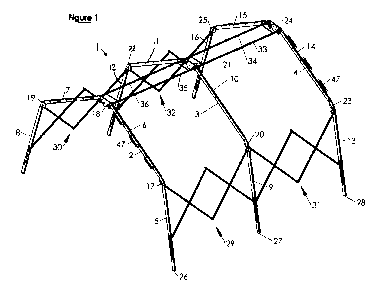
25 Figure 1 illustrates a one-piece collapsible shelter frame (1)
comprising three beam assemblies (2,3,4) each including four
beam members (5,6,7,8;9,10,11,12;13,14,15,16). Each beam member
of a given beam assembly is joined by a pivot unit
(17,18,19;20,21,22;23,24,25) to an adjacent beam member of the
30 beam assembly so as to be reversibly pivotable thereat to a
relatively splayed position collectively to form an arch
(26,27,28)
.
A first arch (26) is joined to a second arch (27) by a first
cross-brace (29) and a second cross-brace (30) each slidably
coupled to beam assemblies of the first and second arches.
CA 02751078 2011-07-28
WO 2010/086668 PCT/GB2010/050147
31
Similarly, a third cross-brace (31) and a fourth cross-brace
(32) join the third arch (28) to the second arch (27) located
between the first and third arches. Each cross-brace is
slidably coupled to each of an opposing pair of successive
arches to reversibly expand therebetween to separate the joined
successive arches permitting a concertina-like expansion and
collapse of the frame in a direction generally transverse to
the plane containing a given arch to draw the arches into close
proximity or contact.
A pair of collapsible top braces (33,34) join the apices of the
second and third arches while a second pair of collapsible top
braces (35,36) join the apices of the second and first arches
(27,26). Each top brace is pivotably coupled to, and between,
adjacent pairs of arches and possesses a fold pivot midway
along its length permitting the given top brace to fold in half
to accommodate the complete collapse of the frame as between
the adjacent arches connected by the top brace. When fully
extended, however, each top brace acts as a restraint to
prevent further expansion or separation between adjacent arches
thereby preventing over-expansion between such arches.
Figure 2 illustrates a frontal view of the first (26) arch (or
the third (28) arch) of the fully erected tent frame (1) of
figure 1 along the long axis of the frame. A first upper beam
member (6) is pivotably connected to a second upper beam member
(7) at a first top pivot unit (18) forming a hinge operable to
permit the first and second beam members to separate from a
closed position in which they are substantially parallel to an
open position in which they are splayed about the hinge (18).
The top hinge is structured to slidably open from a closed
position to a maximally open position at which it is releasably
lockable by locking pins. The maximal splayed angular
separation permitted by the top hinge when locked, is
substantially 110 degrees (or thereabouts). When not in the
locked state, the top hinge (18) permits continuous angular
CA 02751078 2011-07-28
WO 2010/086668 PCT/GB2010/050147
32
displacement of the first and second beam members through
substantially all lesser angles as indicated by arrows 42 in
figure 2.
The end of the first upper beam (6) member free of the top
hinge (18) is pivotably connected to an end of a beam member
(5) defining a side beam of the frame. Similarly, the end of
the second upper beam (7) of the arch free of the top hinge
(18) is also pivotably coupled to an end of a third beam member
(8) defining a side beam of the frame. Each such side beam is
pivotably coupled to a respective upper beam member via a
respective pivot unit (17,19) defining a side hinge. Each such
side hinge is constructed and arranged to allow pivotal
movement of a side beam member relative to the upper beam
member to which it is coupled from a closed state in which the
side beam member and upper beam member are substantially
parallel and in close proximity, to an open state in which the
side beam and upper beam members are splayed apart by a maximum
angle (40,41) determined by the side hinge coupling them. Each
such side hinge is releasably lockable by locking pins operable
to lock the respective upper beam and side beam members when in
the maximally splayed position, and unlockable to permit a
continous pivoting movement of the respective beams through all
of the angles leading to a closed position. Each such side
hinge is structured and arranged to permit a maximal splay
angle (40,41) of substantially 136 degrees, or thereabouts. As
a result, when in the fully opened state in use, the first arch
(2) disposes the long axes of each of its upper beam members at
an inclination of 35 degrees from the horizontal, and disposes
the long axes of each of its side beam members at an angle of
11 degrees from the vertical concurrently. This arrangement has
been found to provide good stability and strength against
lateral stresses such as side winds acting upon the frame in
use as a tent frame.
CA 02751078 2011-07-28
WO 2010/086668 PCT/GB2010/050147
33
When in the fully closed state, each side beam member may be
folded against the accessible side of the upper beam member to
which it is coupled, and the distal end of each side beam
member secured in a stirrup (48) attached to the beam assembly
adjacent to the top hinge and arranged to receive the distal
end of the side beam for storage. Subsequent closure of the two
top beam members (6,7) close all beam members (5,6,7 and 8) of
the beam assembly together as illustrated together in figure
2B.
Each side beam member (5,8) possesses a slot formation (44,46)
passing through the side beam in question and extending along a
portion of the axial length of that beam member. Being formed
through and accessible via surfaces of the beam member adapted
in use to oppose a corresponding beam member of an adjacent
beam assembly of the frame. Housed within the slot formation
(44,46) of the given side beam member is a shuttle member
(43,45) . The shuttle member is retained within, but freely
slidable along, the slot formation within which it is housed
and is dimensioned to project outwardly from the slot formation
at each of the two opposite sides of the side beam member
within which the slot formation is presented. This enables
other components of the frame assembly to be coupled to the
shuttle member and thereby slidingly coupled to the side beam
member which houses the shuttle member in question. Each such
slot formation possesses closed slot ends collectively defining
a closed slot. The shuttle member associated with the given
slot formation is operable to be abutted against the closed
slot end nearmost the side hinge (17,19) to which the side beam
member (5,8) within which it housed, is attached. Each shuttle
member has attached to it a tensioning cable (not shown) which
is simultaneously attached to a part of the associated side
beam member, or side hinge, and operable to be tensioned to
urge the shuttle member attached to it against the closed end
of the slot formation nearmost the side hinge associated with
the side beam in question. In this way the tensioning cable
CA 02751078 2011-07-28
WO 2010/086668 PCT/GB2010/050147
34
acts to effectively lock the shuttle member in a substantially
fixed position within its associated side beam member when the
tensioning cable is appropriately tensioned. Releasing tension
in the tension cable thus enables the shuttle member to slide
along the slot formation. The tensioning cable (not shown) may
comprise a rigging strap or a loop operable to be reversibly
shortened to apply an urging force to the shuttle member as a
result.
Handles (47) are arrayed upon the first and second upper beam
members being spaced along the axial length of each respective
beam upon the outer surface thereof outwardly presented from
the erected arch (2) when operated in use. This positioning
enables a user to use the handles to pull the beam assembly in
the process of expanding the frame into the position shown in
figure 1.
It is to be noted that each of the first (2) , second (3) and
third (4) beam assemblies of the frame is structured and
operable in a manner substantially identical to that described
with reference to figure 2 above with the optional exception
that the second beam assembly (3) intermediate the first (2)
and third (4) beam assemblies may omit any handles (47) as
shown in figure 1, and may possesses side hinges (20,22) which
are not lockable in their maximally open splayed state or are
operable to be maximally opened/splayed without being locked in
that position. This enables a degree of flexibility in the
frame at the intermediate arch (27) formed by the second beam
assembly (3) and permits the feet of the intermediate arch to
adjust to uneven ground surfaces relatively higher or lower
than the ground surface heights at other feet of the frame. To
this extent, a certain small degree of twisting is permitted by
the frame.
Figure 3 illustrates a side view of the fully expanded and
erected tent frame illustrated in figures 1 and 2.
CA 02751078 2011-07-28
WO 2010/086668 PCT/GB2010/050147
The first cross-brace (29) includes a first pair (50) of
crossed arms (50A, 50B) joined at a pivot member (53) where
they cross. The crossed arms of the first pair are operable to
5 pivot about the pivot joint (53) in a scissor-like action.
An end of a first crossed arm (50A) is pivotably attached to
the side beam member of the first arch (26) of the frame
assembly at a hinge (52) fixed in location adjacent to a side
10 hinge (17) of the first arch. Simultaneously, an end of the
second crossed arm (50B) of the first pair (50) is pivotably
attached via a hinge to a shuttle unit (45) slidably attached
to the side beam member (5) to which the end of the first arm
(50A) of the first pair of crossed arms (50) is attached.
The first cross-brace (29) includes a second pair (51) of
crossed arms (51A, 51B) joined at a pivot member (56) where
they cross. The crossed arms of the second pair are operable to
pivot about the pivot joint (56) joining them in a scissor-like
action.
An end of a first crossed arm (50B) is pivotably attached to
the side beam member of the first arch (26) of the frame
assembly at a hinge (57) fixed in location adjacent to a side
hinge (20) of the second arch. Simultaneously, an end of the
second crossed arm (51B) of the first pair (51) is pivotably
attached via a hinge to a shuttle unit (45B) slidably attached
to the side beam member (9) to which the end of the first arm
(51A) of the second pair of crossed arms (51) is attached.
The first arm (50A) of the first pair of crossed arms (50) of
the first cross-brace (29) is pivotably attached (via a pivot
join (55), to the first arm (51A) of the second pair of crossed
arms of the first-brace (29). Simultaneously, the second
crossed arm (50B) of the first pair of crossed arms (50) is
pivotably connected, via a pivoted joint (54), to the second
CA 02751078 2011-07-28
WO 2010/086668 PCT/GB2010/050147
36
arm (51B) of the second pair (50) of crossed arms of the first
cross-brace (29).
Separation of the first (26) and second (27) arches results in
an expansion of the first cross-brace (29) along the direction
of increasing arch separation. Such separation causes the ends
of the first cross-brace (29) slidably coupled to arches via a
shuttle unit (45,45B) to upwardly slide, along associated slot
formations (44,46 etc) towards those parts of the first cross-
brace coupled to an arch via a fixed hinge (52,57 etc), whilst
simultaneously pairs of collapsible top braces (35, 36) unfold
about a mid-hinge assembly (60) as the hinges (58,59) via which
the terminal ends of each top of brace is pivotably attached
(to and between) adjacent beam assemblies are separated.
The second cross-brace (31) includes a third pair (61) of
crossed arms (61A, 61B) joined at a pivot joint (64) where they
cross. The crossed arms of the third pair are operable to pivot
about the pivot joint (64) in a scissor-like action.
An end of a first crossed arm (61A) is pivotably attached to
the side beam member of the second arch (27) of the frame
assembly at a hinge (63) fixed in location adjacent to a side
hinge (20) of the second arch. Simultaneously, an end of the
second crossed arm (61B) of the third pair (50) is pivotably
attached via a hinge to a shuttle unit (45B) slidably attached
to the side beam member (9) to which the end of the first arm
(61A) of the third pair of crossed arms (61) is attached.
The second cross-brace (31) includes a fourth pair (62) of
crossed arms (62A, 62B) joined at a pivot member (67) where
they cross. The crossed arms of the fourth pair are operable to
pivot about the pivot joint (67) in a scissor-like action.
An end of a first crossed arm (62B) is pivotably attached to
the side beam member of the third arch (28) of the frame
CA 02751078 2011-07-28
WO 2010/086668 PCT/GB2010/050147
37
assembly at a hinge (68) fixed in location adjacent to a side
hinge (23) of the third arch. Simultaneously, an end of the
second crossed arm (62A) of the fourth pair (62) is pivotably
attached via a hinge to a shuttle unit (45C) slidably attached
to the side beam member (13) to which the end of the first arm
(62B) of the fourth pair of crossed arms (62) is attached.
The first arm (61A) of the third pair of crossed arms (61) of
the second cross-brace (31) is pivotably attached (via a pivot
joint (66), to the first arm (62B) of the fourth pair of
crossed arms of the second cross-brace (31). Simultaneously,
the second crossed arm (61B) of the third pair of crossed arms
(62) is pivotably connected, via a pivoted joint (65), to the
second arm (62A) of the fourth pair (62) of crossed arms of the
second cross-brace (31).
Separation of the first (26) and second (27) arches results in
an expansion of the first cross-brace (29) along the direction
of increasing arch separation. Such separation causes the ends
of the first cross-brace (29) slidably coupled to arches via a
shuttle unit (45,45B) to upwardly slide, along associated slot
formations (44,46 etc) towards those parts of the first cross-
brace coupled to an arch via a fixed hinge (52,57 etc), whilst
simultaneously pairs of collapsible top braces (35, 36) unfold
about a mid-hinge assembly (60) as the hinges (58,59) via which
the terminal ends of each top of brace is pivotably attached
(to and between) adjacent beam assemblies, are separated.
Separation of the third (28) and second (27) arches results in
an expansion of the second cross-brace (31) along the direction
of increasing arch separation. Such separation causes the ends
of the second cross-brace slidably coupled to arches via a
shuttle unit (45B,45C) to upwardly slide, along associated slot
formations (44,46 etc) towards those parts of the second cross-
brace coupled to an arch via a fixed hinge (63, 68 etc), whilst
simultaneously pairs of collapsible top braces (33, 34) unfold
CA 02751078 2011-07-28
WO 2010/086668 PCT/GB2010/050147
38
about a mid-hinge assembly (71) as the hinges (69,70) via which
the terminal ends of each top of brace is pivotably attached
(to and between) adjacent beam assemblies, are separated.
Figure 4 illustrates a top view of the collapsible frame
illustrated in figures 1 to 3.
The first pair of collapsible braces (33,34) are joined to each
other by a first intermediate tensioning member (80) extending
between them and also by a second intermediate tensioning
member (81) extending between them. Each intermediate
tensioning member is dimensioned and arranged to urge together
the two collapsible top braces to which they are attached. The
result is that a pair of collapsible top-braces otherwise in a
substantially parallel relative state when the frame assembly
is fully expanded, are urged into a state of contact midway, at
the intermediate fold pivot thereof (71,73) midway along each
top brace and, in that orientation, to continue to urge the two
opposing fold pivots. This positioning is illustrated in figure
4 by dashed lines representing all four collapsible top braces
(33,34,35 and 36) in the quiescent state.
This arrangement permits increased structural stability in the
collapsible top braces when the frame is in an expanded state
and a greater degree of support for tent material or sheeting
replaced over the frame when in use as a tent frame.
Figures 4A, 4B, 4C, 4D and 4E each show, in isolation, more
detailed views of aspects of the two pairs of collapsible top
braces of the frame of figures 1 to 4. 54B illustrates a
magnified view of a hinge (75) via which a collapsible top
brace (36) is attached to a beam assembly. This is
representative of each of the hinges via which collapsible top
braces are attached to beam assemblies in the frame.
CA 02751078 2011-07-28
WO 2010/086668 PCT/GB2010/050147
39
Figure 4C illustrates a detailed view of a handle (47) attached
to the outwardly presented surface of terminal beam assemblies
of the frame.
Figure 4D illustrates a magnified view of a fold pivot (71)
midway along the length of a top brace permitting the top brace
to fold in half. The fold pivot independently articulates an
end of each of the two top brace halves separately and at
locations spaced sufficiently to permit each such half to fold
together in a parallel and closed (e.g. touching along their
lengths) state when the top brace in question is collapsed.
Each such collapsible top brace possesses such a fold pivot
midway along its length (60,73,76) . The fold pivot is arranged
to allow the top brace halves of a respective top brace of the
pair of top braces, to fold about the fold pivot in a direction
outwardly and away from the other of the pair of top braces
towards the closed state in which the top brace halves are
disposed in parallel adjacency to the beams to which they are
pivotably joined.
Figure 4E shows a magnified view of a tensioning member (81)
disposed in-between and connected to, each of the first and
second collapsible top braces of the frame. The tensioning
member (81) comprises a length of bungee, the ends of which are
fixed to respective top braces of the pair of top braces via
holes formed therethrough. Figure 4E illustrates the bungee in
a state of tension.
Figure 5 illustrates a magnified view of a side beam member (5)
of the first arch (26) of the erected frame assembly
schematically illustrated by an arrow (Fl) is a direction of
movement or of force supplied by the tensioning means (not
shown) associated with each respective shuttle member (45) of
at least the terminal arches of the assembled frame (2,4) and
optionally also associated with each shuttle unit (45B) of the
second/intermediate arch (3).
CA 02751078 2011-07-28
WO 2010/086668 PCT/GB2010/050147
Motion of a shuttle unit (45) upwardly along a slot formation
(6) in the direction indicated (Fl) urges a corresponding
motion (F2) of the pivot joint (53) via which a cross arm (50B)
5 of the cross brace (29) attached to the shuttle unit is
pivotably connected to another cross arm thereof (50A)
pivotably connected to the side beam member (5) at a fixed
location thereon. In this way, a shuttle unit (45) may be drawn
or urged upwardly along a slot formation within which it is
10 housed, to induce expansion of a cross-brace assembly (29).
Figure 6 illustrates a magnified view of a side beam member (9)
of the second arch (3) and indicates how an upward motion or
urging (F3) of a shuttle unit (46B) of the second arch induces
15 an expanding/opening motion or urging (F4 and F5) in each of
the cross-brace assemblies (29, 31) coupled to the shuttle unit
in common. Reversal of the direction of the motion (F3) of the
shuttle unit accordingly induces a closing/collapsing motion in
the cross-brace assemblies coupled to it.
Figure 7 illustrates a magnified view of a side beam member (9)
of the second arch (3), and the shuttle unit (45B) housed
within it. Figures 8, 9, 10 and 11 illustrate a shuttle unit in
isolation and from a number of different perspectives. All
shuttle units of the frame are substantially identical. The
shuttle unit comprises an elongate plate (94) of thickness (T)
sufficient to allow it to pass through and along the slot
formation (46, 46B, 46C) formed within a given side beam member
of the frame assembly. The plate has a length (L) along its
long axis sufficient to allow terminal ends of the elongate
plate to project simultaneously beyond opposite sides of the
beam member (9) through when it extends, via the slot formation
(Figure 7).
Two pairs of separate plate-mounted roller bearings (91) are
disposed in parallel array on each side/face of the plate. Each
CA 02751078 2011-07-28
WO 2010/086668 PCT/GB2010/050147
41
roller bearing of a pair is separated from an opposing roller
bearing of the other pair on that side of the plate by a
spacing (L2) sufficient to accommodate the width of the side
beam member. The spacing (L2) is also dimensioned and to
permit roller bearings of opposed roller bearing pairs to
simultaneously roll across the surface parts of the side beam
member adjacent the slot formation as the shuttle unit slides
therealong.
Each roller bearing (91) on one side of the plate is coupled to
a roller bearing on the other side of the plate by a common
axle about which both rollers bearings turn in use. Each
roller bearing comprises a tubular roller (92) enveloping a
part of the shaft of an axle (not shown) and arranged to freely
rotate therearound. Each axle comprises a threaded bolt
extending along the inner tubular space of a first of two
tubular rollers, through an opening in the plate (not shown)
and thence along the inner tubular space of a second of the two
tubular rollers. The first tubular roller is retained between
a head (93) of the bolt and a face of the plate. The second
tubular roller is retained between a nut (95) attached to the
threaded end of the bolt, and the other face of the plate.
Attachment through-openings (95) are provided adjacent each of
the two terminal ends of the plate (94) A through-opening
nearmost a cross-brace assembly accepts a pivot bolt (90) via
which the shuttle unit pivotably couples to that cross-brace
assembly. When the shuttle unit is in use in an intermediate
arch or beam assembly (27), each through-opening is so coupled
to a respective cross-brace assembly (Figure 7) . When the
shuttle unit is employed in a terminal arch or beam assembly,
(item 45, Figure 5), a through opening may be employed to
couple the shuttle unit to a tensioning means such as rigging
or tensioning cables, straps of the like as described above.
CA 02751078 2011-07-28
WO 2010/086668 PCT/GB2010/050147
42
Figure 12 illustrates a magnified view of parts of a cross-
brace assembly (29) in an expanded state. Crossed arms of each
of the two pairs of crossed arms of the cross-frame assembly
are pivotably joined by pivot joints (53, 54, 55, 56) which
separate the crossed arms so joined by a common separation (D).
This separation may be reduced, in other embodiments by use of
one or more washers to space the arms where they cross and
provide a bearing surface.
Figures 13, 14 15 and 16 collectively illustrate views of a top
hinge unit (18, 21, 24) comprising a pair of opposed plates
(100, 101) joined at a common axle (104) about which a face of
one plate of the pair is slidingly rotatable over a face of the
other plate of the pair in parallel opposition thereto. In use,
a beam member of a beam assembly is connected to one plate of
the pair and another beam member of the beam assembly is
connected to the other plate of the pair.
One plate (100) of the pair may possess two through-openings
(105) extending from the outwardly presented side of the plate
to the opposed face thereof, and the other plate (101) of the
pair has a pair of orifices (114 of figure 20, 114' of figure
22) disposed in the opposing face thereof to be positionable in
register with the through-opening by rotation of one or both
plates about their common axle to the position shown on figure
17. The through-openings and corresponding orifices are
disposed in a respective plate at opposite sides of the common
axle.
The top hinge includes two pins (102, 103) each insertable into
a respective through-opening (105) and dimensioned to extend
along the through-opening and into an orifice (114 of figure
20, 114' of figure 22) of the opposed face of the other plate
(101) when the through-openings and orifices are concurrently
in register.
CA 02751078 2011-07-28
WO 2010/086668 PCT/GB2010/050147
43
Each pin has a moveable shaft part (110B, 11OB') moveable
relative to the body of the pin along a long axis thereof along
an associated through-opening (105) and into the associated
orifice (114, 114') when in register.
The body of each pin comprises a sleeve part (113, 113')
through which an axial bore extends within which the shaft part
of the pin is slidingly moveable. The shaft and sleeve parts
may be structured and arranged to retain the shaft part within
the sleeve part.
The moveable shaft part of each pin is moveable along the bore
between a retracted state (figure 16) in which the shaft part
does not extend from the sleeve part via an end of the bore,
and a projecting state (figures 20, 22, 24 and 25) in which the
shaft part projects from the sleeve part via an end of the
bore. In the projecting state, the shaft part is dimensioned to
project from the sleeve part into an orifice of a plate of the
top hinge (figures 20, 22) when in register with a through-
opening in an opposing said plate within which the sleeve part
is housed but does not project (e.g. does not project into the
through-opening when in register). When a through-opening and
orifice are not in register, the shaft portion of an associated
pin is arranged to adopt the retracted state (figures 15 and
16). The opposing faces of the plates (100, 101) of the top
hinge are disposed such that the opposing face of the plate
(101) containing the orifice covers the end of the through-
opening (105) via which the shaft part is moveable to project
into the orifice when in register therewith. This covering
maintains the shaft in one plate (100) in the retracted state
until in register with the orifice (114, 114') in the opposing
plate (101). The plates of the top hinge may thus be slidingly
rotatable about their common axle (104) when the shaft of the
pins (102, 103) are retracted, and locked in relative position
by the pins when brought into register.
CA 02751078 2011-07-28
WO 2010/086668 PCT/GB2010/050147
44
The top hinge achieves a maximally splayed/opened state of beam
members joined thereby when the through-opening (105) and
orifice (114, 114') of respective opposed plate faces are in
register.
The moveable shaft part (110B, 11OB') of a pin includes a hand-
operable head part (110A, 110A') turnable by hand to turn the
shaft part about its axis within the bore of the sleeve part.
Each sleeve part has an end part nearmost the head part of the
shaft part of the pin which is shaped (111) to engage with the
head part (110A, 110A', 116) when the shaft part is in a
projecting state (figure 23, figure 24), and to disengage from
the head part when the shaft part is in a retracted state
(figure 16).
The head part of the shaft has a projecting part (116) disposed
to be reversibly moveable, by movement of the head part
relative to the sleeve part, from a first position in which it
engages a recess part (111) of the sleeve part when the shaft
part is in the projecting state (as shown in figures 23 and
24), to a second position (Figure 16) in which it is retracted
from the recessed part (111) and engaged with parts (111B) of
the sleeve part adjacent the recessed part thereof to retain
the shaft part in the retracted state. A pull and turn action
upon the head of the shaft part may effect this movement from
the projecting state to a maintained state of retraction.
Furthermore, in the engaged state (between projecting part 116
and recess part 111) the moveable shaft of a pin is turnable
only if the sleeve part is so turnable, while in the disengaged
state the shaft part is turnable independently of the sleeve
part.
The head part and sleeve part of each pin possess reciprocally-
shaped opposable parts (111, 116; figure 24) dimensioned to
intermesh when engaged such that the shaft part becomes
CA 02751078 2011-07-28
WO 2010/086668 PCT/GB2010/050147
turnable about its axis by turning the head part. This enables
a pin as a whole to be turned in unison about its axis when the
shaft part is projecting into an orifice of a plate from a
through-opening of an opposed plate containing the sleeve part
5 of the pin. As such, the sleeve part of each pin is externally
threaded with a thread (115, figure 23) arranged to engage a
reciprocal threading disposed on the walls of the bore of the
through-opening containing it. This enables the pin, with
projecting shaft part, to be screwed down along the bore of the
10 through-opening to urge until stopped by the opposing plate
containing the orifice in register.
The moveable shaft part of each pin is spring-loaded within the
sleeve part so as to be urged in to a quiescent state of
15 projection therefrom. The bore of the sleeve part is separated
by a spring (112, 112'; figures 16, 20, 22 and 23) from an
opposed abutment surface of the moveable shaft part such that
retraction of the shaft into the bore compresses the spring.
20 Figures 25, 26 and 27 illustrate views of side hinges (17, 23)
structured and operable as described above with reference to
the top hinge of figures 13 to 22. Figure 27 is an exploded
view showing components in separation and including a pair of
spring-loaded locking pins (121, 122) as described above, and
25 opposed plates (117, 119) rotatable about a common axle (130)
of the type described above possessing through-holes (134, 135)
and associated orifices (133, 132) positionable in register to
accommodate locking pins parts in common to lock the side hinge
in an open state.
Each of the side hinges possesses this structure, whereas only
the top and side hinges of terminal arches (26, 28) possess a
tightening nut (120) turnable against a nut (123) about the
common axle (130) of the side hinge to force the opposed plates
together (e.g. into a frictional contact). This enables a
CA 02751078 2011-07-28
WO 2010/086668 PCT/GB2010/050147
46
strengthening of the frame. Figure 28 illustrates an exploded
view of a top hinge with a tightening nut.
Figure 29 illustrates a top hinge in which a face of one plate
(119) thereof is marked with the word "FRAME" at a location
which is brought into adjacency to a part of the second plate
marked "closed" only when the top hinge is closed, and which is
brought into adjacency to a part of the second plate marked
"open" only when the top hinge is fully opened. The tightening
nut (120) may be tightened in either position to further secure
the top hinge in the open of closed state.
Figure 30 illustrates a tent (130) comprising the tent frame
described above over which a tent covering (145) is draped and
attached. Door drapes (135) are located at a first arch (26),
side-wall drapes (140) are located over side beam members and
cross-beam assemblies (29, 31) which provide strength at the
side walls (140) of the tent.
Slot-openings (not shown), according to any embodiment of the
invention, may be provided in the tent covering (145) at
locations which coincide, when the tent covering is applied to
the erected tent frame (1), with the locations of handles (47)
being such that handles at opposite ends of the frame may be
slotted through the slot-openings to assist in securing the
tent covering to the tent frame. The tent covering is
preferably of a length selected such that slotting the frame
handles through slot openings in this way applies a tension to
the covering along the long axis of the frame thereby to apply
a compressive force to the frame which is resisted by the
frame. This opposition of forces assists in "holding" the tent
frame more firmly in an upright or erected state.
In alternative embodiments of the invention, a side hinge (17,
20, 23, 19, 22, 25) and/or a top hinge (18, 21, 24) may be
CA 02751078 2011-07-28
WO 2010/086668 PCT/GB2010/050147
47
structured and arranged as is illustrated in figures 31A to 31C
and 32A to 32C, or 33A to 33C and 34A to 34C respectively.
Figures 31A, 31B and 31C show different views of one part of a
top hinge unit possessing a plate (150) across a face of which
a pair of circularly arcuate channels (154, 155) extend in
diametrical opposition about an aperture (151) arranged to
receive the axle of the hinge unit.
Figures 32A, 32B and 32C show different views of a second part
of the top hinge of which the parts of figures 31A to 31C form
a part. The second part includes a plate (156) with two lugs
(157B and 157A) extending therefrom in a direction parallel to
the axis of the common axle (not shown) about which the first
and second hinge parts are adapted to rotate when opposed in
use. The two lugs are disposed on the face of the second plate
(156) in diametrical opposition about an aperture (152)
arranged to receive the axle of the hinge unit so as to extend
into a respective one of the two arcuate channels (154, 155)
formed across the opposing face of the first plate of the pair
of plates in use. A first lug (157A) is slideable along a first
arcuate channel (155) from a first end (155A) of the channel to
a second end (155B) thereof by action of relative rotation of
the opposed plates. The first lug abuts the first end of the
channel when the top hinge unit is in a fully splayed/opened
state, and the lug abuts the second end of the channel when the
top hinge unit is in the closed state.
A second lug 157B is slideable along the second arcuate channel
(154) from a first end (154A) of the channel to a second end
(154B) thereof by action of relative rotation of the opposed
plates. The second lug abuts the first end of the channel when
the top hinge unit is in a fully splayed/opened state, and the
lug abuts the second end of the channel when the top hinge unit
is in the closed state.
CA 02751078 2011-07-28
WO 2010/086668 PCT/GB2010/050147
48
Figures 33A, 33B and 33C show different views of one part of a
side hinge unit possessing a plate (158) across a face of which
a pair of circularly arcuate channels (160, 161) extend in
diametrical opposition about an aperture (159) arranged to
receive the axle of the hinge unit.
Figures 34A, 34B and 34C show different views of a second part
of the side hinge of which the parts of figures 33A to 33C form
a part. The second part includes a plate (162) with two lugs
(164B and 164A) extending therefrom in a direction parallel to
the axis of the common axle (not shown) about which the first
and second hinge parts are adapted to rotate when opposed in
use. The two lugs are disposed on the face of the second plate
(162) in diametrical opposition about an aperture (163)
arranged to receive the axle of the hinge unit so as to extend
into a respective one of the two arcuate channels (160, 161)
formed across the opposing face of the first plate of the pair
of plates in use. A first lug 164A is slideable along a first
arcuate channel (160) from a first end (160A) of the channel to
a second end (160B) thereof by action of relative rotation of
the opposed plates. The first lug abuts the second end of the
channel when the side hinge unit is in a fully splayed/opened
state, and the lug abuts the second end of the channel when the
side hinge unit is in the closed state.
A second lug 164B is slideable along the second arcuate channel
(161) from a first end (161A) of the channel to a second end
(161B) thereof by action of relative rotation of the opposed
plates. The second lug abuts the first end of the channel when
the top hinge unit is in a fully splayed/opened state, and the
lug abuts the second end of the channel when the top hinge unit
is in the closed state.
One or more pins such as illustrated in figures 23 and 24 may
be incorporated with either of both of the top hinge and side
hinge of these alternative embodiments, wherein on of the two
CA 02751078 2011-07-28
WO 2010/086668 PCT/GB2010/050147
49
opposed plates of a hinge has a through-opening housing the
sleeve part and retractably extendible shaft part of the pin,
while the other of the two opposed plates possesses an orifice
disposed to be brought into register with the through-opening
(e.g. when the hinge is in the fully splayed state) to admit a
projecting end of the shaft part of the pin therein.
Referring to figures 35, 36 and 37, figure 35 illustrates an
exploded view of a lockable hinge shown in figure 36 in
assembled (unexploded) form. The hinge includes a pair of
opposed hinge members (204, 207) including plate portions
connected at a common axle (202) about which a face of the
plate portion of the first hinge member (204) of the pair is by
operation of the hinge slidingly rotatable over a face (not
shown) of the plate portion of the second hinge member (207) of
the pair in parallel opposition thereto. The hinge includes a
lock means operable to rotate a locking member (211) reversibly
into a position which obstructs the sliding rotation of one of
the pair of hinge members relative to the other of the pair
hinge members from a position which does not so obstruct
thereby reversibly to lock the hinge. Each of the first and
second hinge members (204, 207) is so slidingly rotatable
relative to the other. The hinge members are flat plates with
opposing faces bounded by a circular edge (in part) and have
extension parts (204a, 207a) extending away from a part of the
circular edge to define an arm via which a hinge member is
connectable to an article/assembly to be articulated by the
hinge. An example is a frame, ladder, scaffold, platform or
other structure with articulated parts which may be so
articulated via the hinge. For example, a connector arm of
opposing hinge members may be connected to different
articulated assembly members. Screw holes or bolt holes (e.g.
four in square array) may be provided in the distal end of a
connector arm of a hinge member for fixing or connecting the
hinge member to an assembly part to be articulated. The four
illustrated hinge members, and all their spacer or guide plates
CA 02751078 2011-07-28
WO 2010/086668 PCT/GB2010/050147
(205, 206, 208, 210) discussed below are bound together at the
extension parts via mutual screws or bolts or the like (not
shown) passing through each if a respective one of four screw
holes as shown. A first spacer plate (205) is bound between,
5 and separates, the extension parts of the second and fourth
hinge members (207, 201) and presents a concave peripheral edge
in intimate opposition to the convex circular peripheral edge
(slidable) of the first hinge member. A second spacer plate
(208) is a guide plate (discussed below) bound between, and
10 separates, the extension parts of the first and third hinge
members (204, 209) and presents a concave peripheral edge in
intimate opposition to the convex circular peripheral edge
(slidable) of the second hinge member. Outer guide plates (206,
210) are bound to the extension parts of the third and fourth
15 hinge members respectively and disposed to present a concave
peripheral edge in intimate opposition to the convex circular
peripheral edge (slidable) of, respectively, the third and
fourth hinge members.
20 The lockable hinge includes a third hinge member (209)
comprising a plate portion connected to the second hinge member
(207) at the common axle (202) about which a face of the plate
portion of the third hinge member (not shown) is by operation
of the hinge slidingly rotatable over an opposing surface of
25 the plate portion of the second hinge member (207) in parallel
opposition thereto. The plate portion of the second hinge
member is sandwiched between the plate portions of the first
and third hinge members which are slidingly rotatable thereover
in unison. The first and third hinge members are fixed
30 together at opposing extension parts (arms 209a, 204a) thereof
which extend from, and in the plane of, a respective first and
third plate portions. Screws (not shown) are provided through
screw holes formed in the extension parts (204a, 209a) of the
first and third hinge members to fix the two members together.
CA 02751078 2011-07-28
WO 2010/086668 PCT/GB2010/050147
51
In this way a laminate structure is provided comprising four
opposing slidable surfaces, two of which are opposite sides of
the plate portion of the second hinge member (207) sandwiched
between two outer plate portions of the first and third hinge
members. The first and third hinge members are joined via
their extension parts so as to be rotatable together in unison
relative to the second hinge member.
The hinge includes a fourth hinge member (201) comprising a
plate portion connected to the first hinge member (204) at said
common axle about which a surface of a plate portion of the
fourth hinge member is by operation of the hinge slidingly
rotatable over a surface (not shown) of the first hinge member
(204) in parallel opposition thereto. Accordingly, parts of the
plate portion of the first hinge member are sandwiched between
the plate portions of the fourth (201) and second (207) hinge
members which are slidingly rotatable thereover in unison. The
second and fourth hinge portions are fixed together at opposing
extension parts thereof (201a, 207a) which extend from, and in
the plane of, a respective second and fourth plate portions.
Screws (not shown) are provided through screw holes formed in
the extension parts of the second and fourth hinge members to
fix the two members together.
Accordingly, a laminate structure is provided comprising six
opposing slidable surfaces: one inwardly-facing surface of each
of the third (209) and fourth (201) hinge members and each face
(both sides) of the first (204) and second (207) hinge members.
Each such sliding surface is in contact with the neighbouring
opposing surface of the laminate. The locking member is
attached to the first and third hinge members (204, 208) of the
laminate and a locking recess is formed in the peripheral edge
of the intermediate opposing pate part of the second hinge
member sandwiched therebetween.
CA 02751078 2011-07-28
WO 2010/086668 PCT/GB2010/050147
52
Between the inwardly-facing surface of the fourth hinge member
(201) and an opposing face (not shown) of the second hinge
member (207) extend two lug parts (203) each fixed within (e.g.
screwed) and extending between associated opposing pairs of lug
holes formed in opposing faces of the plate parts of the second
and fourth hinge members. The lug parts each extend from the
plate portions in question into and through a respective
separate one of two separate associated circularly curved,
closed slots (214, 215) formed across (and through) the surface
of the plate portion of the first hinge member. Each one of
the two lug parts is slideable along a respective slot from one
end thereof to another end thereof by action of relative
rotation of the first and fourth hinge members. The ends of
the respective slits are disposed such that both lugs are
slideable to abut an end of (either end) their slot in unison.
The slots have the same angular extent of 120 between extreme
configuration of which one is an "open" configuration and one
is a "closed" configuration - each defined by the abutting of
each lug at one or other end of their respective slots.
The circularly curved slots are dimensioned such that a lug
part abuts an end thereof when the hinge members are positioned
such that the locking member (211) is rotatable to lock the
hinge as illustrated in figure 35.
In other configurations, the peripheral circular edge of the
second hinge member prevents rotation of the cam (211) into an
obstructing position. Referring to figures 35, 36 and 37 the
locking member (211) comprises a cam (211) with a cam shaft
(212). The first hinge member and the third hinge member each
include a cam shift bore (218, 224) within which is intimately
received a respective part of the cam shaft on opposite sides
of the cam. The cam shaft is rotatable about its axis, so
received, to correspondingly rotate the cam attached to it. The
cam is sandwiched between the plate portions of the first and
third hinge members. An inner terminal end (212a) of the cam
CA 02751078 2011-07-28
WO 2010/086668 PCT/GB2010/050147
53
shaft is located within the cam bore of the first hinge member.
An outer terminal end of the cam shaft (212b) protrudes from
the outermost surface of the third hinge member and has
attached to it a handle (212) fixed to the cam shaft by a screw
(213).
The handle (212) extends generally transversely from the axis
of the cam shaft to point in a first direction (e.g. generally
away from, such as radially away from the axle) relative to the
third hinge member (209) when the hinge is in the unlocked
state and to point in a second direction (e.g. generally
towards the common axle) relative to the third hinge member
when the hinge is in the locked state.
The common axle extends through the first, second, third and
fourth hinge members via axle through-holes (226, 222, 225, 227
respectively) in the opposing surfaces of the four hinge
members. The circular peripheral edges of each of the four
hinge members is circumferential to the axle through openings
of that hinge member.
The locking member including the cam (211) mounted upon the
rotatable cam shaft, is shown in figures 38 and 38. The cam
shaft is operable reversibly to rotate the cam such that an
eccentric portion (211a) of the cam is positioned to obstruct
sliding rotation of second and fourth hinge members (fixed
together) relative to the first and third hinge members (fixed
together). This reversibly locks the hinge. The cam has an
eccentric portion (211a) shaped substantially as a circular
segment of 110 extent circumferential to the axis of the cam
shaft (212). The circular segment has a distal peripheral edge
defined by a constant maximal radius centred upon the cam
shaft. The cam defines elsewhere a peripheral edge (211b)
closer to the cam shaft. The cam is dimensioned such that when
no part of the distal peripheral edge obstructs sliding
CA 02751078 2011-07-28
WO 2010/086668 PCT/GB2010/050147
54
rotation of the hinge members, then nor does any other part of
the peripheral edge of the cam.
In alternative embodiments, the locking member may be linearly
slideable radially to and from the obstructing position by a
action of applying a radial force to the cam shaft towards or
away from the common axle. In that example, the cam shaft bores
(218, 224) of the first and third hinge members may be replaced
by slots which extend linearly radially towards the common axle
to permit sliding movement of the cam shaft (212) therealong to
accommodate sliding movement of the cam (211) to and from the
obstructing position. The guide recess (219) may then also be
replaced by a slot dimensioned to slidingly admit the whole cam
(211). In other embodiments, the cam (211) may be replaced by a
rod, bolt or block so moveable radially to/from a reciprocally
shaped recess in an edge of the second hinge member
positionable to accept it in the obstructing position to lock
the hinge by a linear movement.
The locking member is attached to the first and third hinge
members to place the cam adjacent the peripheral edge of the
plate portion of the second hinge member which contains a
locking recess (220). The locking recess (220) is defined
where the peripheral edge of the plate portion of the second
hinge member is closer to the common axle (202) than are parts
of that edge immediately adjacent the locking recess i.e. the
convex circular edge parts bounding the concave circular edge
part defining the recess. It is shaped and adapted to admit
the cam eccentric to lock the hinge.
The locking recess is positionable, by relative rotation of the
hinge members, between the cam shaft and the common axle (202)
of the hinge to place the locking recess in a position to admit
the cam by rotation of the cam shaft.
CA 02751078 2011-07-28
WO 2010/086668 PCT/GB2010/050147
The locking recess and those parts of the cam to be admitted
into the locking recess are complementarily shaped. The cam is
dimensioned and arranged to be positionable to substantially
fully occupy the locking recess. The eccentric parts of the cam
5 adapted to be positionable within the locking recess have an
outermost edge which has a constant radius of curvature. The
locking recess presents a concave recess edge having a radius
of curvature centred on the same point of curvature (the cam
shaft central axis) as the cam eccentric. The angular extent
10 of the eccentric is 110 degrees which is greater than the
angular extent of the correspondingly shaped locking recess
(220).
The first hinge member includes a separable guide plate part
15 (208) which is fixed to the extension part (204a) of the first
hinge part. See figures 43A and 43B. The guide plate part
defines a concave guide edge (208a) positioned to oppose the
peripheral edge of the plate part of the second hinge member.
Opposed edges of second hinge member (207) and the guide plate
20 (208) of the first hinge member (204) collectively define a
discharge conduit (280). This extends from a discharge inlet
opening (280a) immediately adjacent the locking recess (220) to
a discharge outlet opening (280b) at the periphery of the hinge
(see figures 45 and 46). It is adapted to conduct debris urged
25 therein from the locking recess by action of rotation of the
locking member into the locking recess and towards the
discharge inlet. Turning the cam eccentric into the locking
recess serves to push unwanted debris out of the locking recess
and into a dedicated conduit. The guide plate (208) of the
30 first hinge member includes a rotation stop (230, figure 43A)
arranged to prevent continued rotation in one direction of the
cam beyond a position in which the cam eccentric does not
obstruct relative rotation of said hinge members and in the
opposite direction beyond a position in which the cam eccentric
35 does so obstruct.
CA 02751078 2011-07-28
WO 2010/086668 PCT/GB2010/050147
56
Figures 39A and 39B, 40A and 40B, 41A and 41B and 42A and 42B
show plan and side views of the first, second, third and fourth
hinge members respectively.
Figures 43A and 43B show a plan and a side view of the guide
plate of the first hinge member.
Figures 40A and 40B show a plan and a side view of the guide
plates (202, 203, 209) attached to hinge members by screws (not
shown) via screw holes. One of each of the guide plates
presents a concave edge in opposition to the peripheral curved
edge of the plate portion of one of each of the hinge members.
Figure 45 shows first and second hinge members in the locked
state with the cam eccentric fully occupying the locking recess
and abutting one side of the cam stop. Third and fourth hinge
members are not shown and may be omitted.
Figure 46 shows first and second hinge members in the unlocked
state with the cam eccentric fully vacated from the locking
recess and abutting the other side of the cam stop. The hinge
is rotated into position in which the cam cannot lock the
hinge. Third and fourth hinge members are not shown and may be
omitted.
Figure 47 shows first and second hinge members in the locked
state with the cam eccentric fully occupying the locking recess
and abutting one side of the cam stop. Third and fourth hinge
members are not shown and may be omitted. The second hinge
member (270) is an alternative hinge member (e.g. a replacement
hinge member from a kit of parts comprising such replacements)
having two spaced locking recesses (220, 220a) permitting
different locking configurations of the hinge. The hinge member
comprising the locking recess may include a plurality of
separate such locking recesses spaced about that edge to permit
CA 02751078 2011-07-28
WO 2010/086668 PCT/GB2010/050147
57
the locking of the hinge in any one of a respective plurality
of hinge configurations.
Figure 48 shows first and second hinge members in the locked
state with the cam eccentric fully occupying the locking recess
and abutting one side of the cam stop. Third and fourth hinge
members are not shown and may be omitted. The second hinge
member (700) is an alternative hinge member (e.g. a replacement
hinge member from a kit of parts comprising such replacements)
having two spaced arcuate channels for guiding lug portions
fixed to and extending from the opposing face (not shown) of
the first hinge member (400) This embodiment comprises a
first hinge member having none of the arcuate channels shown in
figure 35.
Figure 49 shows a transparent plan view of the hinge of figure
35 showing the lug portions abutted against terminal ends of
respective arcuate channels (thereby preventing onward rotation
of the hinge) when the locking recess is fully in register with
the cam and positioned to admit the cam to lock the hinge.
Figures 50A to 50C, 51A to 51C, 52A to 52C and 53A to 53C show
alternative embodiments of the invention excluding the
aforesaid lock means and optionally excluding the third and
fourth hinge members.
Figures 50A to 50C show different views of one part (e.g. a
first hinge member) of a hinge unit possessing a plate (350)
across a face of which a pair of circularly arcuate channels
(354, 355) extend in diametrical opposition about an aperture
(351) arranged to receive the axle of the hinge unit.
Figures 51A to 51C show different views of a second part of the
hinge (e.g. a second hinge member) of which the parts of
figures 50A to 50C form a part. The second part includes a
plate (356) with two lugs (357B and 357A) extending therefrom
CA 02751078 2011-07-28
WO 2010/086668 PCT/GB2010/050147
58
in a direction parallel to the axis of the common axle (not
shown) about which the first and second hinge parts are adapted
to rotate when opposed in use. The two lugs are disposed on
the face of the second plate (356) in diametrical opposition
about an aperture (352) arranged to receive the axle of the
hinge unit so as to extend into a respective one of the two
arcuate channels (354, 355) formed across the opposing face of
the first plate of the pair of plates in use. A first lug
(357A) is slideable along a first arcuate channel (355) from a
first end (355A) of the channel to a second end (355B) thereof
by action of relative rotation of the opposed plates. The
first lug abuts the first end of the channel when the hinge
unit is in a fully splayed/opened state, and the lug abuts the
second end of the channel when the hinge unit is in the closed
state.
A second lug (357B) is slideable along the second arcuate
channel (354) from a first end (354A) of the channel to a
second end (354B) thereof by action of relative rotation of the
opposed plates. The second lug abuts the first end of the
channel when the hinge unit is in a fully splayed/opened state,
and the lug abuts the second end of the channel when the hinge
unit is in the closed state.
Figures 52A to 52C show different views of one part (e.g. a
first hinge member) of a hinge unit possessing a plate (358)
across a face of which a pair of circularly arcuate channels
(360, 361) extend in diametrical opposition about an aperture
(369) arranged to receive the axle of the hinge unit.
Figures 53A to 53C show different views of a second part of the
hinge (e.g. a second hinge member) of which the parts of
figures 52A to 52C form a part. The second part includes a
plate (362) with two lugs (364B and 364A) extending therefrom
in a direction parallel to the axis of the common axle (not
shown) about which the first and second hinge parts are adapted
CA 02751078 2011-07-28
WO 2010/086668 PCT/GB2010/050147
59
to rotate when opposed in use. The two lugs are disposed on
the face of the second plate (362) in diametrical opposition
about an aperture (363) arranged to receive the axle of the
hinge unit so as to extend into a respective one of the two
arcuate channels (360, 361) formed across the opposing face of
the first plate of the pair of plates in use. A first lug
(364A) is slideable along a first arcuate channel (360) from a
first end (360A) of the channel to a second end (360B) thereof
by action of relative rotation of the opposed plates. The
first lug abuts the second end of the channel when the hinge
unit is in a fully splayed/opened state, and the lug abuts the
second end of the channel when the hinge unit is in the closed
state.
A second lug (364B) is slideable along the second arcuate
channel (361) from a first end (361A) of the channel to a
second end (361B) thereof by action of relative rotation of the
opposed plates. The second lug abuts the first end of the
channel when the hinge unit is in a fully splayed/opened state,
and the lug abuts the second end of the channel when the hinge
unit is in the closed state.
One or more lock means such as described hereinbefore may be
incorporated with any of the hinges of these alternative
embodiments, in the manner described hereinbefore. For example,
one of the two opposed plates of a hinge may have a lock means
attached thereto including a lock member moveable (e.g.
rotatable or linearly slideable) to move by a movement parallel
to the opposed sliding surfaces of the hinge plates, reversibly
move a lock member into a recess or notch formed by the other
of the two opposed plates thereat to obstruct or prevent
sliding rotation of one plate relative to the other.
Figure 54 schematically shows an alternative embodiment of the
invention in which a first hinge member (350) has extending
into a peripheral circular edge a linear slot (342) adapted to
CA 02751078 2011-07-28
WO 2010/086668 PCT/GB2010/050147
intimately receive a complimentarily shaped bolt plate (310)
when in register with the bolt plate. The bolt plate is
slidingly connected to a first hinge member (360) for sliding
movement into and out of a guide slot in the guide plate
5 thereof. Linear sliding movement of the locking bolt (310) by a
movement substantially parallel to the opposing sliding
surfaces of the first and second hinge members is permitted
when the locking recess (340) is revolved into register with
the locking bolt (310).
Figure 55 schematically illustrates an alternative embodiment
in which the locking recess is in the form of a chord (330)
defining a linear peripheral edge part of the otherwise
circular peripheral edge of a second hinge member plate (370)
against and away from which a bolt (320) is slideable by a
linear movement substantially parallel to the opposing surfaces
of the plates of the first and second hinge members (370, 380)
of this embodiment. A guide recess is provided in the guide
plate of the first hinge member (380) to accommodate the
locking bolt (320) when in a non-obstructing position. The
guide edge also provides an edge against which the locking bolt
may register when also registered against the opposite surface
of the chord of the locking recess in the locked state. In this
way the locking bolt (320) may be sandwiched between the edge
of the chord (330) and an opposing edge of the guide plate
(380) to retain the locking bolt (320) in the obstructing
position.
It is to be understood that the frame described herein may
comprise any hinge described herein (e.g. the lockable hinge,
or otherwise).
The scope of the foregoing descriptions are not intended to
limit the scope of the invention and are intended merely to
provide some examples of embodiments of the invention.
Alternatives and variants to aspects of these embodiments, such
CA 02751078 2011-07-28
WO 2010/086668 PCT/GB2010/050147
61
as would be readily apparent to the skilled person, are
encompassed within the scope of the invention, e.g. as defined
by the claims.