Note: Descriptions are shown in the official language in which they were submitted.
CA 02751272 2015-01-26
LOCK CYLINDER MONITOR.
Background
This invention relates generally to lock monitoring systems, and more
particularly to a
lock monitoring system for determining the position of a lock cylindor in a
mortise lock
assembly.
There are a number of' different ways that users have attempted to make looks
"tamper
proof' using lock monitoring systems. Some systems incorporate alarms
associated with the
insertion of an incorrect key into a lock cylinder. The alarms cooperate with
the inner workings
of the look cylinder, such as the pin/tumbler assembly, to signal when them is
tampering with the
pin/tumbler assembly within the cylinder. The alarms provide an audio or
visual indication, or
trigger a locking mechanism, when the pins within the lock cylinder are
improperly manipulated.
Other conventional lock monitoring systems signal an alarm when the lock
assembly is
being pried or jimmied or otherwise forcibly engaged. The lock assembly
includes sensors and,
when there is an attempt to pry or damage the lock assembly or surrounding
frame, the sensors
signal an alarm.
Lock monitoring systems do not typically address the position of the lock
cylinder. In a
mortise lock assembly, the lock cylinder rotates a cam to place the look in a
locked condition or
an unlocked condition, as well as to retract a latch or a deadbolt to a
retracted position.
Therefore, the rotation of the lock cylinder is usually an indication of
either ingress or egress
through the door.
Mortise lock assemblies vary in size arid depth. Similarly, lock cylinders
also vary in
size and depth, as does the shape and design of the cam. Thus, it is difficult
to provide a lock
-1-
CA 02751272 2011-07-28
WO 2010/088611 PCT/US2010/022751
monitoring system for a lock cylinder that will work effectively with all
mortise lock assemblies
and lock cylinders.
For the foregoing reasons, there is a need for a lock monitoring system that
monitors the
position of the lock cylinder. The new lock monitoring system should signal an
alarm, or be
integrated into an alarm system where rotation of the lock cylinder may be
monitored for
security reasons. Ideally, the new lock monitoring system should be applicable
to new and
existing mortise lock assemblies, especially in a retrofit application.
Summary
The present invention provides for a cylinder lock monitor for monitoring the
cylinder
position. The monitor has a housing having an inner cavity and an exterior
diameter, the exterior
diameter being no greater than the corresponding cylinder diameter. The
monitor also includes a
switch received into the inner cavity of the housing. The switch is in
electrical communication
with an indicator. The monitor also includes a spring for urging the switch
into the inner cavity
of the housing, and a retainer for holding the spring adjacent to the switch.
The present invention further provides for a cylinder lock assembly having a
cylinder
lock, and a cylinder lock monitor for monitoring the cylinder's position. The
cylinder lock
monitor includes a housing having an inner cavity and an exterior diameter,
the exterior diameter
being no greater than the corresponding cylinder diameter, a switch received
into the inner cavity
of the housing, the switch in electrical communication with an indicator, a
spring for urging the
switch into the inner cavity of the housing, and a retainer for urging the
spring to remain adjacent
to the switch.
Another aspect of the present invention provides for a mortise lock assembly
having a
mortise lock body, a cylinder lock, and a cylinder lock monitor assembly for
monitoring the
cylinder's position. The cylinder lock monitor assembly has a housing having
an inner cavity
and an exterior diameter, the exterior diameter being no greater than the
corresponding cylinder
diameter. The cylinder lock monitor assembly further includes a switch
received into the inner
cavity of the housing, the switch in electrical communication with an
indicator. The cylinder
lock monitor assembly also includes a spring for urging the switch into the
inner cavity of the
housing, and a retainer for urging the spring to remain adjacent to the
switch.
-2-
CA 02751272 2011-07-28
WO 2010/088611 PCT/US2010/022751
Brief Description of the Drawings
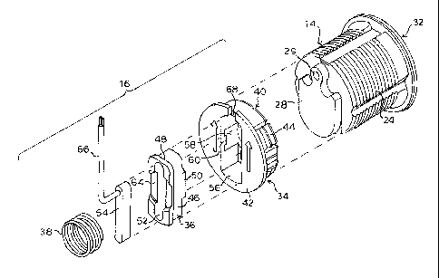
FIG. 1A is an exploded perspective view of a mortise lock assembly.
FIG. 1B is a perspective view of an embodiment of a lock cylinder monitoring
assembly
as shown in FIG 1.
FIGs. 2A and 2B are exploded views from opposite sides of the lock cylinder
monitoring
assembly and lock cylinder as shown in FIG. 1A.
FIG. 3 is a front elevation view of the lock cylinder monitoring assembly as
shown in
FIG 2.
FIG. 4 is a cross-section view of the lock cylinder monitoring assembly taken
along line
4-4 of FIG. 3.
FIG. 5 is cross-section view of the lock cylinder monitoring assembly taken
along line 5-
of FIG. 3.
FIG. 6A is a side elevation view of the lock cylinder monitoring assembly and
lock
cylinder as shown in FIG. 1 in a first position relative to a mortise lock
housing.
FIG. 6B is a side elevation view of the lock cylinder monitoring assembly and
lock
cylinder as shown in FIG. 6A in a second position relative to a mortise lock
housing.
FIG. 7A is an elevation view of a cam of a lock cylinder and a portion of a
lock cylinder
monitoring assembly in a first relative position taken along line 7A-7A of
FIG. 3.
FIG. 7B is an elevation view of the cam and the portion of the lock cylinder
monitoring
assembly as shown in FIG. 7A in a second relative position.
FIGs. 8A and 8B are a perspective view and an exploded perspective view,
respectively,
of another embodiment of a lock cylinder monitoring assembly.
FIGs. 9A and 9B are a perspective view and an exploded perspective view,
respectively,
of the lock cylinder monitoring assembly shown in FIGs. 8A and 8B from the
opposite side as
shown in FIGs. 8A and 8B.
FIG. 10 is a front elevation view of the lock cylinder monitoring assembly as
shown in
FIGs. 8A-9B.
FIG. 11 is a cross-section view of the lock cylinder monitoring assembly taken
along line
11-11 of FIG. 10.
FIG. 12 is cross-section view of the lock cylinder monitoring assembly taken
along line
12-12 of FIG. 10.
-3-
CA 02751272 2015-01-26
FIG, 13A is a side elevation view of the lock cylinder monitoring assembly and
lock
cylinder as shown in FICis. &A-9B in a first position relative to a mortise
lock housing.
FIG, 13B is a side elevation view of the lock cylinder monitoring assembly and
lock
cylinder as shown in FIG. 13A in a second position relative to a mortise lock
housing.
Description
The embodiments of a lock cylinder monitoring assembly described herein is for
use in a
mortise lock and may be used with any conventional mortise lock such as, for
example, the
mortise locks described by U.S. Patent No. 6,393,878 and U.S. Patent No,
6,349,982,
Accordingly, detailed explanations of
the functioning of all of the components of the mortise lock are deemed
unnecessary for
understanding of the present invention by one of ordinary skill in the art.
Certain terminology is used herein for convenience only and is not to be taken
as a
limitation on the invention, For example, words such as "interior",
"exterior", "upper," "lower,''
"left," 'Pright," "horizontal," "vertical," "upward," and "downward" merely
describe the
configuration shown in the FIGs. Indeed, the components may be oriented in any
direction and
the terminology, therefore, should he understood as encompassing such
variations unless
spe,cified otherwise.
Referring now to the drawings, wherein like reference numerals designate
corresponding
or similar elements throughout the several views, FIGs, 1A and 1B shows an
embodiment of a
mortise lock assembly generally designated at 10. The mortise lock assembly IO
is conventional
and only a few of the mortise lock components are shown, including a lock case
12 and a key-
operated lock cylinder 14. Also shown in FIG. 1 is an embodiment of a lock
cylinder monitoring
assembly, generally designated at 16,
As is known in the art, the mortise look case 12 is adapted to fit into a
mortised recess
formed in the edge of a door (not shown) which is opposite to the edge of the
dour that is hinged
to a door frame. The lock case 12 is generally rectangular and encloses the
lock components.
The principal lock components are a beveled latch bolt 18, a deadbolt 20 and
an auxiliary bolt
22. Both of the latch bolt 18 and the deadbolt 20 may project from the case 12
beyond the edge
of the door and into openings in the door frame to latch or lock the door in a
closed position.
The latch bolt 18 and deadbolt are moveable to a retracted position inside the
case 12 to permit
-4.
CA 02751272 2011-07-28
WO 2010/088611 PCT/US2010/022751
opening of the door by operation of a latch operator (not shown), such as a
door knob or lever
handle.
The lock cylinder 14 has an elongated threaded body 24. The cylinder body 24
accommodates a rotatable key plug 26, the inner end of which carries an
eccentric cam 28.
Rotation of the key plug 26 by a key in the cylinder body 24 causes
corresponding rotation of the
cam 28. The major side walls of the lock case 12 define opposed circular
openings 30 in the
upper rear comers for threadably receiving the lock cylinder 14. During
installation of the
mortise lock 10, a transverse opening is drilled in a face of the door and
opens into the recess in
the edge of the door. The transverse opening is positioned to align with the
openings in the lock
case 12 when the lock case 12 is in the recess. The lock cylinder 14 is
inserted into the
transverse opening and threaded into the opening 30 on one side of the lock
case 12. The lock
cylinder 14 is advanced into the lock case 12 until an outer trim flange 32 is
flush against the
door surface. The distance the cylinder body 24 advances into the lock case 12
will vary based
on the thickness of the door.
As is known in the art, the cam 28 is adapted to operatively engage lock
components to
effect a locked condition and an unlocked condition of the mortise lock 10.
Optionally, the cam
28 may function to selectively extend and retract the deadbolt 20 or retract
the latch bolt 18. All
of the operations of the cam 28 require rotation of a key in the lock cylinder
14 for rotating the
key plug 26 and the cam 28.
Referring to FIGs. 2A and 2B, the lock cylinder monitoring assembly 16
comprises a
housing 34, a plunger 36 and a coil spring 38. The monitor housing 34 is a
generally circular
member, including an inner portion 40 of some depth and a generally planar
outer flange portion
42. The outer flange portion 42 has a larger diameter than the inner portion
40 of the housing.
The periphery of the inner portion 40 of the housing includes four flexible
tabs 44 depending
inwardly from the flange portion 42.
The plunger 36 is a generally rectangular member, including an inner portion
46 of some
depth and a generally planar outer flange portion 48 of slightly larger
dimensions than the inner
portion 46 of the plunger 36. The inner portion 46 of the plunger 36 has an
axial boss 50
extending partially along the inner surface. The plunger 36 defines an oblong
recess 52 for
receiving a switch 54. The switch 54 is fixed within the recess 54 using any
number of suitable
adhering means such as the application of an adhesive such as glue. Other
methods of fixing the
-5-
CA 02751272 2011-07-28
WO 2010/088611 PCT/US2010/022751
switch 54 within the plunger recess 52 are contemplated. They include but are
not limited to
mechanical means such as screws and pins, as well as other chemical means such
as epoxy resin,
as well as heat so as to melt the switch 54 within the recess 52. In an
assembled position, the
switch 54 is completely embedded within the switch recess 52 in the plunger
36.
The monitor housing 34 defines a pass through opening 56 which is sized and
shaped to
slidably receive the plunger 36. A pair of opposed arcuate walls 58 further
define the opening 56
at the midpoint and partially form a spring recess. A pair of opposed axial
tabs 60 extend
inwardly into the arcuate portions of the opening 56. The inner end of the
opening 56 is defined
by end walls 62 that extend transversely for partially closing the opening 56.
To assemble the lock cylinder monitoring assembly 16, the plunger 36 and
switch 54 are
slipped into the opening 56 in the housing 34. The plunger 36 slides freely
within the housing
34. Inward axial movement of the plunger 36 is limited by engagement of the
outer flange
portion 48 of the plunger 36 with the end walls 62 at the inner end of the
opening 56. The spring
38 is then placed within the opening 56 in the spring recess partially defined
by the arcuate inner
walls 58 of the housing 34. The outer surface of the plunger 36 defines a
partial circular recess
64 for receiving the inner end of the spring 38. The spring 38 is held in
compression by
positioning the outer coil under the tabs 60. The spring 38 thus serves to
hold the plunger 36
within the housing 34 while biasing the plunger 36 against the end walls 62,
as best seen in FIGs.
4 and 5. It is understood that other means for inwardly biasing the plunger 36
are possible.
Thus, we do not intend ourselves to limit to the specific embodiments of the
spring biasing
means shown herein.
The inner portion 40 of the monitor housing 34 is sized to be received in the
cylinder
opening 30 in the case 12 opposite the lock cylinder 14. Referring to FIGs. 6A
and 6B, the inner
portion 40 of the housing 34 is press fit into the opening 30 in the case 12.
As the housing 34
advances into the case 12, the flexible tabs 44 on the flange portion of the
housing 34 engage the
case 12 adjacent the opening 30 and flex inwardly. As the housing 34 advances
into the case 12,
the tabs 44 clear the wall of the case 12 and snap outwardly. Ridges on the
tabs thus engage the
inner surface of the wall for holing the lock cylinder monitoring assembly 16
in the lock case 12.
As described above, during installation of the mortise lock 10, the lock
cylinder 14 is
inserted through an opening in the door face and threaded into the opening 30
in the lock case
12. As the lock cylinder 14 is threaded into the case 12, the boss 50 on the
plunger 36 initially
-6-
CA 02751272 2011-07-28
WO 2010/088611
PCT/US2010/022751
engages the cam 28 of the lock cylinder 14. As the lock cylinder 14 advances,
the plunger 36 is
pushed into the housing 34 against the force of the spring 38 until the trim
flange 32 on the lock
cylinder 14 is flush against the door surface. Thus, the lock cylinder
monitoring assembly 16 is
able to accommodate varying depths of lock cylinder 14 intrusion into the case
based lock
cylinder bodies 24 of varying lengths and varying door thicknesses.
In an assembled position, the lock cylinder 14 and the lock cylinder
monitoring assembly
16 make frictional contact at the cam 28 and the boss 50. A magnet 29 is
embedded flush with
the surface of the cam 28 so that the cam 28 is free to rotate within the lock
case 12. In one
= embodiment, the switch 54 is a Reed switch, which operates by an applied
magnetic field. The
switch 54 has at least one pair of electrical contacts (not shown) therein.
The contacts remain
either normally open or normally closed when a magnetic field is applied. In
one embodiment,
the contacts within the switch 54 are normally closed when a magnetic field is
applied. Thus,
if the magnet 25 were to move upon rotation of the cam 24, the switch 54 would
open at the
absence of a magnetic field for generating an electric signal indicating that
the cam 28 has
moved. As seen in the FIGs., electrical wiring 66 is provided for electrically
connecting the
switch 54. A radial notch 68 in the flange portion 42 of the housing 34 is
sized and dimensioned
to pass the wire 66.
FIG. 7A shows the cam 28 in an initial home position where switch 54 is
aligned with the
magnet 29 embedded in the cam 28. When a key is inserted in the key plug 26,
the key, key plug
26 and cam 28 can rotate together for effecting a lock function. FIG.7B shows
the position of
the cam 28 after rotation from the home position. When the cam 28 rotates, the
magnet 29
moves away from the switch 54. Because the switch 54 is able to indicate
presence or loss of
magnetic field, if the switch 54 is normally closed the switch 54 opens and
thus disrupts the
normal flow of current in the circuit. This sends an electrical signal over
the wire 66 generally
indicating that the cam 28 has moved from its home position.
The wire 66 from the switch 54 may be connected to a remote alarm or other
indicator
(not shown). The indicator may be an audio or visual signal, or may be
connected to an
alarm/security system where the signal from the indicator may be recorded as
an event for
security auditing, shunt an alarm when cylinder use is acceptable (i.e.
cylinder used to open door
instead of electronic credential (keycard, pin code)), or notify security or
initiate an alarm at a
time when cylinder use is not acceptable. Uses of the signal from the switch
54 may be
-7-
CA 02751272 2011-07-28
WO 2010/088611 PCT/US2010/022751
expanded to accommodate specific security requirements as well as alarm system
monitoring
capabilities.
Referring now to FIGs. 8A-9B, another embodiment of a cylinder lock monitoring
assembly is shown and generally designated at 70. The lock cylinder monitoring
assembly 70
comprises a housing 72, a plunger 74 and a coil spring 76. As in the previous
embodiment, the
monitor housing 72 is a generally circular member, including an inner portion
78 and an outer
flange portion 80 of a larger diameter and including four inwardly depending
flexible tabs 82. In
this embodiment, the outer flange portion 80 further comprises a planar
extension 92 which
projects upwardly and terminates in a perpendicular flange 94 that extends
inwardly from the
extension 92.
The plunger 74 is a generally X-shaped member. The plunger 74 defines a
central
circular blind bore 84 for receiving the spring 76. A switch sensitive to a
magnetic filed is
integral with the plunger 74. The monitor housing 72 defines an X-shaped pass
through opening
86 which is sized and shaped to slidably receive the plunger 74. A pair of
opposed axial tabs 88
extend inwardly into the opening 86. The housing 72 also has a pair of opposed
axial tabs 90 at
the inner end of the opening 86 that extend transversely into the opening 86.
To assemble the lock cylinder monitoring assembly 70, the plunger 74 is
slipped into the
opening 86 in the housing 72 and slides freely within the housing 72. Inward
axial movement of
the plunger 74 is limited by engagement of the tabs on walls 96 connecting the
legs of the
plunger 74. The spring 76 is then placed within the 84 and positioning the
outer coil under the
tabs 88. As in the previous embodiment, the spring 76 thus serves to hold the
plunger 74 within
the housing 72 while biasing the plunger 74 inwardly against the tabs 90, as
best seen in FIGs. 11
and 12.
The inner portion 78 of the monitor housing 72 is received in the cylinder
opening 30 in
the lock case 12 in the same manner as the previous embodiment. Referring to
FIGs. 13A and
13B, in this embodiment the extension 92 lies against the wall of the case and
flange 94 fits into
a slot 98 in the top wall of the case 12. In use, this embodiment of the lock
cylinder monitoring
assembly 70 functions the same way as the previous embodiment. As the lock
cylinder 14 is
threaded into the opening 30 in the lock case 12, the plunger 74 initially
engages the cam 28 and
is pushed into the housing 72 against the force of the spring 76 until the
trim flange 32 on the
lock cylinder 14 is flush against the door surface. In use, the switch
integral with the plunger 74
-8-
CA 02751272 2015-01-26
senses the magnet 29 in the cam 28. Accordingly, the switch generates an
electric signal
indicating that the cam 28 has moved, which signal is communicated via the
electrical wiring 66.
It is understood that the embodiments of the lock cylinder monitoring assembly
described
herein may be retroflt to existing single cylinder mortise lock designs. The
mortise lock
assembly would be.installed as a standard mortise lock assembly, except that
the wiring from the
switch to the indicator would need to be provided.
Although the present invention has been shown and described in considerable
detail with
respect to only a few exemplary embodiments theteof, it should be understood
by those skilled in
the art that we do not intend to limit the invention to the embodiments sinoe
various
modifications, omissions and additions may be made to the disclosed
embodiments without
materially departing from the novel teachings and advantages of the invention,
partioularly in
light of the foregoing teachings. Accordingly, we intend to cover all such
modifications,
omission, additions and equivalents as may be included
as defined by the following claims. In the claims, means-plus-function clauses
are
intended to cover the structures described herein as performing the recited
function and not only
structural equivalents but also equivalent structures. Thus, although a nail
arid a screw inay not
be structural equivalents in that a nail employs a cylindrical surface, to
secure wooden parts
together, whereas a screw employs a helical surface, in the environment of
fastening wooden
parts, a nail and a serew may be equivalent structures.
-9-