Note: Descriptions are shown in the official language in which they were submitted.
CA 02751824 2016-09-06
FINISHER WITH ON-BOARD LOADING AND UNLOADING MECHANISM
[0001] This paragraph is intentionally left blank.
FIELD OF THE INVENTION
[0002] This invention relates to a finisher arrangement for
surface finishing of loose parts, which arrangement includes a
centrifugal surface finishing apparatus having loading and
unloading mechanisms integrated therewith to facilitate loading
and unloading of parts and media into and out of the finishing
apparatus, and also relates to a process for operating such
arrangement.
BACKGROUND OF THE INVENTION
[0003] Finisher arrangements for surface finishing of
parts by effecting movement of parts within media
contained within an upwardly-opening bowl-shaped
finishing apparatus are well known, and the finishing
operation carried out by such apparatus is well understood.
Frequently such finishing apparatus is provided with suitable
associated hardware, including mechanisms, to facilitate
loading, as well as unloading, of parts and media into or out
of the bowl. Such arrangements have typically employed a
container or hopper arrangement for permitting media and/or
parts to be deposited therein, with the hopper then being
moved to permit the parts to be discharged through the upper
open mouth of the bowl into the finishing chamber. The movement
of the hopper has, in known instances, employed swinging arms
which enable vertical swinging of the hopper from a lowered
filling position into a raised position above the finishing bowl
for permitting discharge of the hopper contents. Such apparatus
is also known wherein the finishing bowl itself is mounted for
1
CA 02751824 2011-09-07
=
vertical swinging movement to permit the contents thereof,
upon completion of the finishing operation, to be discharged
from the bowl back into a hopper. In this known arrangement,
however, the hopper and the bowl are provided with separate
swing arm mechanisms which move about wholly separate and
distinct swing axes. In addition, the swinging mechanisms
associated with the hopper and the finishing bowl are
independently driven by separate power devices. This
arrangement results in the overall arrangement being of
greater size and bulk, of greater structural complexity, and
hence of greater overall cost.
[0004] Arrangement of the aforementioned type have caused
the parts, when discharged from the hopper into the finishing
bowl to be dropped vertically through a substantial distance,
=
and a substantial vertical drop is also normally encountered
when the finished parts are discharged from the bowl back into
the hopper. This significant vertical dropping of the parts
during transfer has been observed to cause undesirable hitting
and impacting of the parts against one another, which can be
damaging to the surface finish of the parts, particularly in
the case of delicate and/or high precision parts.
[0005] In addition, in the apparatus of the aforementioned
type, the rotor adjacent the bottom of the finishing bowl is
typically rotated only throughout the actual finishing
operation, but is maintained stationary during loading of the
parts into the finishing bowl, and is also maintained
stationary (i.e., non-rotating) when the bowl is swingably
moved into a discharge position. This stationary condition of
the bowl rotor, however, is believed to cause the parts, when
deposited into or discharged from the bowl, to be transferred
under conditions which results in more contacting and
impacting of the parts with one another.
[0006] Accordingly, it is an object of this invention to
provide an improved finisher arrangement for parts, which
finisher arrangement includes a centrifugal-type finishing
bowl having improved mechanisms and hardware associated
2
CA 02751824 2011-09-07
therewith to facilitate swinging movement of both a hopper and
the bowl to facilitate respective loading and unloading of
parts and finishing media. The overall arrangement of this
invention is believed to provide improved structural and
operational simplicity, and more specifically a smaller and
more compact overall arrangement which facilitates operation
of the arrangement and provides improved access and
visibility.
[0007] It is also an object of this invention to provide an
improved operational process for such arrangement, which
process includes maintaining slow rotational movement of the
bowl rotor both when parts and media are deposited into the
bowl, and when the bowl is in its raised and tilted position
to discharge the parts and media into a collecting structure.
The slow rotation of the rotor, both during loading and
unloading of the bowl, and its action on the parts and media
within the bowl, is capable of effecting greater spreading of
the parts over the bottom of the bowl, rather than permitting
the parts to bunch more closely together such as typically
occurs when rotor rotation is stopped. This slow rotation of
the rotor hence prevents the parts from being deposited or
discharged in a large mass, but rather spreads the deposited
or discharged the parts more uniformly over the depositing or
discharge time cycle, thereby minimizing impacting between the
parts when they undergo the transfer motion.
[0008] A further object of the invention, as aforesaid, is
to provide the overall arrangement with minimal vertical drop
between the bowl and the hopper arrangement, both when the
hopper is positioned over the bowl to permit deposit of parts
and media therein, and when the bowl is positioned in tilted
relationship above the hopper assembly to discharge parts and
media thereto. This minimal discharge or drop distance is
particularly achieved in the arrangement of this invention by
supporting the hopper in a geometric relationship relative to
the bowl so that, when the hopper is swung upwardly into
position over the bowl, the lower part of the hopper projects
3
CA 02751824 2016-09-06
downwardly into the interior of the finishing chamber defined by
the bowl. This relationship, combined with the provision of an
openable discharge passage defined at the bottom of the hopper,
permits the parts and media to be vertically dropped a very
small and substantially minimal distance when deposited from the
hopper onto the bottom wall of the bowl.
[0009] Other objects and purposes of the invention will be
apparent to persons familiar with arrangements of this general
type upon reading the following specification and inspecting the
accompanying drawings.
SUMMARY OF THE INVENTION
[0009.1] In accordance with one aspect of the invention, there
is provided a finisher arrangement for surface finishing parts,
comprising: a frame; a drive unit comprising a rotary actuator
mounted on the frame and including a rotary drive shaft
supported for rotation about a substantially horizontal axis; a
handling device supported in a first position disposed closely
horizontally adjacent a first side of the rotary drive shaft,
the handling device including an upward opening hopper for
accommodating therein a mixture containing a quantity of
finishing media and a plurality of loose parts; a centrifugal
finishing device supported in an operational position disposed
closely horizontally adjacent a second side of the rotary drive
shaft, the centrifugal finishing device comprising an open bowl-
shaped container defining therein an upwardly opening finishing
chamber for deposit of the mixture therein; a first drive
linkage drivingly connectable between the handling device and
the rotary drive shaft for vertical upward swinging movement of
the handling device about the substantially horizontal axis from
the first position into a second position wherein the upward
opening hopper is disposed over a mouth of the upwardly opening
4
CA 02751824 2016-09-06
finishing chamber for enabling discharge of the mixture from the
upward opening hopper into the centrifugal finishing chamber;
and a second drive linkage drivingly connectable between the
centrifugal finishing device and the rotary drive shaft for
vertical upward swinging movement of the centrifugal finishing
device about the substantially horizontal axis from the
operational position into an unloading position wherein the open
bowl-shaped container is disposed in a partially inverted
position generally above the handling device for discharge of
the mixture from the open bowl-shaped container into the
handling device.
[0009.2] In accordance with another aspect of the invention,
there is provided a process of operating the finisher
arrangement as described above, comprising: providing a rotor at
a bottom of the upwardly opening finishing chamber for mixing
the mixture within the upwardly opening finishing chamber;
rotating the rotor at a first rotational speed when the mixture
is discharged from the upward opening hopper into the
centrifugal finishing chamber; thereafter rotating the rotor at
a second rotational speed to effect surface treatment of the
parts contained within the mixture; and thereafter rotating the
rotor at a third rotational speed as the open bowl-shaped
container is moved into the unloading position and during
discharge of the mixture from the open bowl-shaped container;
wherein the second rotational speed is greater than the first
rotational speed and the third rotational speed.
[0009.3] In accordance with a further aspect of the invention,
there is provided a finisher arrangement for surface finishing
parts, comprising: a frame; a drive unit mounted on the frame; a
handling device including an upward opening hopper for
accommodating therein a mixture containing a quantity of
finishing media and a plurality of loose parts; a centrifugal
finishing device comprising an open bowl-shaped container
4a
CA 02751824 2016-09-06
defining therein an upwardly opening finishing chamber for
deposit of the mixture therein; a first drive linkage drivingly
connectable between the handling device and the drive unit for
swinging movement of the handling device from a first home
position to a second position wherein the upward opening hopper
is disposed over a mouth of the upwardly opening finishing
chamber for enabling discharge of the mixture from the upward
opening hopper into the centrifugal finishing chamber; and a
second drive linkage drivingly connectable between the
centrifugal finishing device and the drive unit for swinging
movement of the centrifugal finishing device from an operational
position to an unloading position wherein the open bowl-shaped
container is disposed in a partially inverted position generally
above the handling device for discharge of the mixture from the
open bowl-shaped container into the handling device; the
handling device being in the first home position when the
centrifugal finishing device is in the unloading position and
the centrifugal finishing device being in the operation position
when the handling device is in the second position; the first
drive linkage comprising at least one first drive arm rotatably
connected to the handling device; the second drive linkage
comprising at least one second drive arm rotatably connected to
the centrifugal finishing device; and a driving arm configured
to be selectively engaged with either the at least one first
drive arm or the at least one second drive arm; the driving arm
rotating the at least one first drive arm with actuation of the
drive unit when the driving arm is engaged with the at least one
first drive arm, thereby moving the handling device between the
first home position and the second position; the driving arm not
rotating the at least one first drive arm with actuation of the
drive unit when the driving arm is not engaged with the at least
one first drive arm; the driving arm rotating the at least one
second drive arm with actuation of the drive unit when the
4b
CA 02751824 2016-09-06
driving arm is engaged with the at least one second drive arm,
thereby moving the centrifugal finishing device between the
operational position and the unloading position; and the driving
arm not rotating the at least one second drive arm with
actuation of the drive unit when the driving arm is not engaged
with the at least one second drive arm.
[0010] The finishing arrangement of this invention includes
a simple compact frame having an upright pedestal provided with
a rotary drive device, such as a rotary hydraulic actuator,
mounted thereon and disposed so that a drive shaft thereof
projects transversely and generally horizontally of the frame.
A centrifugal-type finishing device of generally conventional
construction, namely an upwardly opening bowl having a rotatable
rotor defining the bottom of a finishing chamber, is disposed
closely adjacent one side of the rotary actuator. A parts/media
handling device is normally positioned closely adjacent the
other side of the rotary actuator. A pair of driving arm
mechanisms are disposed adjacent opposite sides of the frame
so as to straddle the centrifugal finishing bowl and the
parts/media handling device. Each arm arrangement includes
a first elongate arm which at one end is fixed to the bowl
and at its other end is rotatably supported on the drive
shaft and cooperates with an engagable coupling device so as
to be drivingly coupled to the drive shaft to effect upward
swinging of the bowl into a discharged position upon
activation of the rotary actuator. Each arm arrangement also
includes a second elongate arm which has its inner end
rotatably engaged with the drive shaft and its outer end
rotatably engaged with the parts/media handling device.
This second arm also cooperates with a second
4c
CA 02751824 2011-09-07
coupling device which, when engaged, enables the second arm to
be vertically swingably displaced by the rotary actuator to
swing the handling device into a position wherein a hopper
associated with the device is positioned over and projects
down into the bowl to permit depositing of media and parts
therein. The second arm also has an anti-tilt mechanism
associated therewith so that, when the second arm is swingably
displaced, the parts/media handling arrangement remains in a
level or generally horizontal orientation. The first and
second arms both swingably move about the same transverse
axis, namely the axis defined by the drive shaft associated
with the rotary actuator, and the disposition of the bowl and
handling apparatus directly adjacent and on opposite
diametrical sides of the rotary actuator when they are in
their normal lowered positions, simplifies and minimizes the
overall size of the apparatus and of the required frame, and
facilitates access and visibility on behalf of operating
personnel. The parts/media handling device, in addition to
the hopper, includes a tray arrangement disposed above the
hopper and including an upper grate which permits separation
of parts from media and liquid, with media and liquid passing
vertically downwardly through the grate to a screen disposed
therebelow, which screen permits liquid to pass vertically
downwardly for collection, with the media collecting on the
screen being discharged into the hopper.
[0011] In the operation of the arrangement as described
above, when the hopper is swung upwardly into a position over
the finishing bowl during initiation of a finishing cycle, but
prior to discharge of parts and media from the hopper into the
bowl, the rotor associated with the bottom of the finishing
chamber is activated so as to slowly rotate. Thereafter the
gate at the bottom of the hopper is opened to provide
controlled discharge of parts and media onto the slowly-
rotating rotor which immediately effects outward dispersion of
the parts so as to minimize buildup of parts at the center of
the rotor, and hence minimize impacting of the parts against
CA 02751824 2011-09-07
one another during the discharge from the hopper into the
finishing chamber. In addition, after the parts have been
finished due to higher rotation of the rotor within the
finishing chamber and the resulting tumbling and mixing of the
parts and media within the bowl, the rotor speed is again
reduced to a low rotational speed, and the swing arms
connected to the bowl are drivingly engaged and swung upwardly
so that the bowl is swung upwardly through an angle in excess
of 90 degrees, causing the bowl to be positioned over the tray
arrangement with the bowl being in a slightly downwardly
inverted and angled relationship. In this relationship, there
is a tendency for the mass of parts and media to remain
somewhat clumped together adjacent a lower corner of the
chamber, and the slow rotation of the rotor and the ribs
thereon cause some of the parts and media to be lifted
upwardly within the bowl in the vicinity of the bottom wall
thereof, which hence reduces the speed with which the parts
are discharged, and hence results in the discharge of parts
occurring in a more uniform manner, rather than being
discharged as one big mass. This accordingly minimizes the
impacting of the parts with one another, particularly when the
parts contact the grate and their falling motion is stopped,
whereby less surface damage is believed to occur due to the
improved discharge motion achieved by the continued slow
rotation of the rotor during the discharge phase.
BRIEF DESCRIPTION OF THE DRAWINGS
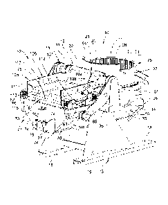
[0012] Figure 1 is a perspective view of an improved
finisher arrangement having parts/media loading and unloading
capabilities in accordance with the present invention, which
view illustrates a centrifugal parts finisher and a
parts/media handling arrangement disposed in their normal
lowered positions in close proximity to one another but
disposed on generally opposite sides of a single centrally-
positioned rotary drive.
6
CA 02751824 2011-09-07
[0013] Figure 2 is a perspective view similar to Figure 1
but illustrates the parts/media handling apparatus swung
upwardly into a raised position wherein it is disposed over a
finishing chamber defined by the parts finisher so as to
permit discharge of parts and media from a hopper into the
finishing chamber.
[0014] Figure 3 is a perspective view taken generally from
the diametrically opposite side of the arrangement shown in
Figure 2.
[0015] Figure 4 is a perspective view which illustrates the
parts/media handling arrangement in its lowered normal
position, and the parts finisher swung upwardly into a raised
position wherein the bowl is partially inverted and disposed
in close proximity over a tray of the parts/media handler to
permit discharge of parts, media and liquid from the bowl into
the tray.
[0016] Figure 5 is a diagrammatic top view of the finisher
arrangement when the finishing device and handling arrangement
are in their lowered positions substantially as illustrated in
Figure 1.
[0017] Figure 6 is a side elevational view taken from the
bottom side of Figure 5 and showing the overall arrangement in
its lowered or normal condition.
[0018] Figure 7 is an end elevational view taken from the
rightward end of Figure 5 and showing the rotary centrifugal
finishing bowl.
[0019] Figure 8 is a fragmentary sectional view which
illustrates the basic construction of the bowl and
specifically the rotatable spinner or rotor associated with a
bottom of the finishing chamber.
[0020] Figure 9 is a view taken from the rightward end of
Figure 5 and showing the relationship of the arm mechanism to
the main drive shaft.
[0021] Figure 10 is a perspective view, taken dominantly
from the leftward end of Figure 5, and illustrating the
7
CA 02751824 2011-09-07
parts/media handling structure, namely the hopper arrangement
and the vibratory tray structure disposed thereabove.
[0022] Figure 11 is a fragmentary view taken generally from
the leftward end of the arrangement and showing the arm
arrangement and its cooperation with the output shaft and the
parts/media handling apparatus.
[0023] Certain terminology will be used in the following
description for convenience and reference only, and will not
be limiting. For example, the words "upwardly", "downwardly",
"rightwardly" and "leftwardly" will refer to directions in the
drawings to which reference is made. The words "inwardly" and
"outwardly" will refer to directions toward and away from,
respectively, the geometric center of the arrangement or
apparatus, or designated parts thereof. Said terminology will
include the words specifically mentioned, derivatives thereof,
and words of similar import.
DETAILED DESCRIPTION
[0024] Referring to the drawings, and specifically Figures
1-5, there is illustrated a finisher arrangement 10 in
accordance with the present invention. This finisher
arrangement includes a parts finisher 11 of the centrifugal
type, and a material handling apparatus 12, both of which are
supported for vertical swinging movement on a support frame
13. The parts finisher 11 and the material handler 12 are
both connected to a linkage arrangement 14 which includes
substantially identical arm assemblies 15 disposed on opposite
sides of the finisher arrangement for permitting independent
and selective vertical swinging of the parts finisher 11 and
material handler 12. A rotary drive arrangement 16 is mounted
on the frame and extends transversely thereacross at a
location between the finisher apparatus 11 and handler 12 for
providing driving coupling engagement to each of the arm
assemblies 15, as described hereinafter.
[0025] The frame 13 is of a small and compact design and
includes a base defined by a pair of horizontally elongate
8
CA 02751824 2016-09-06
rails or skids 18 which are sidewardly disposed in generally
parallel relationship, and a pedestal 19 which transversely
rigidly joins the skids together at a location intermediate the
ends thereof. The pedestal is cantilevered upwardly and is
disposed generally between the sidewardly-adjacent finisher
apparatus 11 and material handler 12 when the latter are in
their normal lowered positions as illustrated by Figures 1 and
5. The finisher device 11 and handler 12, when in this lowered
normal position, are supportingly seated on seats or supports
which are fixed to the frame 13.
[0026] The rotary drive unit is comprised by a single
conventional rotary hydraulic actuator 21 which includes an
elongate cylindrical housing 22 fixedly mounted on the upper end
of the pedestal 19 so as to extend generally transversely and
horizontally crosswise of the apparatus. This hydraulic drive
unit includes an internal torque generating mechanism, typically
of the helical type, which effects rotation of an output shaft
23 which in the illustrated unit projects coaxially outwardly
from opposite ends of the housing and is rotatable about its
longitudinal central axis 24, the latter being oriented to
extend horizontally in transverse relationship to the lengthwise
extent of the overall arrangement. The rotary hydraulic drive
actuator 21 enables the output shaft 23 to be reversely rotated
through a desired angular extent, while enabling generation of
significantly high output torque. Rotary hydraulic actuators
are conventional and well known, and one common brand is
manufactured by Helac.
[0027] With respect to the parts finisher 11, it comprises a
centrifugal type finishing device 26 which is generally well
known, and the basic structure and operation thereof is
described in U.S. Patent No. 5,012,620. However, the basic
structure and operation of the finishing device 26 is briefly
described herein for purposes of completeness.
9
CA 02751824 2011-09-07
[0028] The finishing device 26 includes a bowl or tub-
shaped container 27 which defines an upwardly-opening
finishing chamber 28 (Figures 5 and 8). The bowl 27 is
defined principally by a bottom wall 29 joined to an upwardly-
projecting annular edge or side wall 31 which terminates at a
free upper edge. A radially enlarged rotor 32, sometimes
referred to as a spinner, is positioned adjacent and overlies
the bottom wall and is coupled to a drive shaft 33 which
projects vertically downwardly in sealed relationship through
the bottom wall 29 for joinder to a drive gear mechanism 35,
which in turn is joined to a drive motor 36. The drive gear
mechanism 35 and drive motor 36 are both carried on the bowl
27. The upper surface of the rotor can be provided with ribs
or protrusions to assist in mixing of the chamber contents.
[0029] The rotor 32 and bottom wall 29 cooperate to define
a pressure chamber 38 therebetween which is supplied with
fluid, for example water, which is utilized in the finishing
operation. The fluid is supplied to the chamber 38 from a
suitable supply pipe 39 having a control valve 41 associated
therewith. The supply pipe 39 in turn is joined through a
flexible pipe or conduit to a suitable pressurized supply
source for the fluid.
[0030] As illustrated in Figure 8, the rotor 32 extends
radially so as to cover substantially the entire bottom wall
29 and hence the upper surface of the rotor defines the active
bottom wall of the finishing chamber 28. The annular outer
edge of the rotor cooperates with the surrounding annular
housing to define an annular seal 42, the latter being defined
by an annular tip 43 on the rotor, the latter typically being
of a suitable flexible material, and cooperating with an
annular seal part 44 provided on the side wall. These seal
parts define a suitable narrow gap, particularly when the
chamber 32 is filled with pressurized fluid, to allow limited
flow of pressurized fluid upwardly through the seal into the
finishing chamber 28. This effectively cools the seal,
CA 02751824 2011-09-07
prevents fines and other solids from contaminating the seal,
and provides longer seal wear life.
[0031] The liquid is drained from the finishing chamber 28
through one or more ports 45 formed in the rotor, which ports
in turn communicate with a passage 46 which extends coaxially
downwardly through the drive shaft, the latter passage being
connected in a conventional manner to a suitable drain or
liquid collecting arrangement.
[0032] AS is conventional, the inner surface of the annular
side wall 31 and the exposed upper surface of the rotor 32 are
preferably provided with a suitable lining or coating thereon,
typically a coating of urethane.
[0033] To control vertical swinging movement of the
finishing device 26 from its loading and operational position
of Figure 1 into its dumping or unloading position of Figure
4, the pair of arm arrangements 15 each include a first
elongate swing arm 51 having its inner end rotatably supported
on the drive shaft 23, and its outer end rigidly joined to a
side mounting flange 52 which is fixed to the side wall of the
tub adjacent the lower extremity thereof.
[0034] To affect driving, each arm mechanism 15 includes a
driving arm member 53 formed as a generally L-shaped lever
member which, adjacent its apex, is non-rotatably secured to
the drive shaft 23 so that the arms 54 and 55 thereof project
radially outwardly. The one arm 54 projects so as to be
disposed in close sideward proximity to the first elongate
swing arm 51, and a drive coupler or clutch device 56 is
provided for creating a driving coupling therebetween. The
drive coupler 56 comprises a generally linear activator 57
which is mounted on the swing arm 51 and has a linearly
extendable coupling pin 58 which projects transversely toward
the arm 54 so that when the activator 57 is actuated, such as
electrically or pneumatically, the pin 58 moves outwardly to
project into an opening 59 formed through the drive arm 54,
thereby non-rotatably coupling the swing arm 51 to the arm 54
which in turn is non-rotatably coupled to the drive shaft 23.
11
CA 02751824 2011-09-07
Rotary activation of the drive shaft 23 by the hydraulic
actuator 21 thus effects vertical swinging of the finishing
device 26 between the normal operational and loading position
illustrated in Figure 1 and the unloading position illustrated
in Figure 4.
[0035] The frame 13 is also provided with support arms
which protrude outwardly from the pedestal 19 and project
under the bowl 27 to provide stationary support for the bowl
when in its normal operational and loading position.
[0036] As illustrated by Figures 1 and 6, the bowl 27 is
preferably provided with an upwardly projecting discharge
guide 64 associated with the upper edge of the finishing
chamber. This guide 64 extends circumferentially around only
a fraction of the circumference of the open mouth of the bowl,
namely through an angle significantly less than 180 degrees,
typically about 135 degrees, and is positioned so as to be on
the side of the bowl which is disposed most closely adjacent
the rotary actuator 21. The guide 64 projects upwardly only a
limited extent, such as about four to six inches above the top
edge of the bowl side wall, and is provided solely to provide
an extended guide path for permitting slidable discharge of
parts and media from the bowl when the latter is in the raised
and tilted unloading position of Figure 4. When in this
latter position, the guide 64 assists in bridging the gap so
as to permit more controlled and smooth discharge of parts
into the material handler 12, as described hereinafter.
[0037] Considering now the material handler 12, it will be
understood that the primary puLpose of the material handler 12
is to handle both parts and media which are initially
collected therein and then loaded into the finishing device
26, and to also receive and effect separation of the parts,
media and liquid which are unloaded from the finishing device
26 back into the material handler 12 when the finishing device
is in the raised unloading position shown by Figure 4.
[0038] The material handler 12 includes an upwardly opening
hopper arrangement 71 defined by spaced apart upright front
12
CA 02751824 2011-09-07
and back walls 72 and 73 rigidly joined by side walls 74
which, in their lower extremities, taper inwardly toward one
another. These latter walls cooperate to define a chamber 75
for permitting collection of media and parts therein, with the
deposit of media and parts into the chamber 75 occurring
through the open upper end 76 of the hopper. The lower end or
bottom of the hopper 71, as defined between the inwardly
converging side walls 74, defines a discharge opening which is
normally closed by an openable gate which, in the illustrated
arrangement, comprises a pair of swingable bombay doors 77
supported by hinges 78 which extend along lower edges of the
sloping side walls 74. The bombay doors 77 are connected to a
linkage 79 which in turn connects to an extendable piston rod
of a control cylinder 81, such as a pneumatic cylinder. The
latter when in its raised position maintains the bombay doors
77 closed but, when the cylinder is activated so that the
piston is moved downwardly, the linkage 79 is lowered causing
the bombay doors 77 to hingedly swing downwardly into an open
position to allow discharge of the contents from the hopper.
[0039] The hopper
arrangement 71 is rigidly secured to and
between a pair of generally horizontally elongated support
rails 82 (Figure 1) which, in the normal operating position
illustrated by Figure 1, project generally horizontally toward
the frame pedestal. The support rails 82 each mount thereon a
downwardly projecting support block 83, the latter in turn
mounting a sidewardly and horizontally protruding support
shaft 84 (Figure 5). The support shafts 84 on opposite sides
of the hopper are horizontally coaxially aligned and define a
transverse horizontal axis 85. The outwardly protruding
support shafts 84 as disposed on opposite sides of the hopper
individually cooperate with outer ends of second elongate
swing arms 86 associated with the arm arrangements 15. Each
swing arm 86 has the outer end thereof rotatably supported on
the respective support shaft 84, and the other or inner end is
rotatably supported on the drive shaft 23. The swing arm 86
is, as illustrated in Figure 5, positioned relative to the
13
CA 02751824 2011-09-07
swing arm 51 so that the driving arm member 53 is positioned
therebetween relative to their axially adjacent positional
relationships on the drive shaft 23.
[0040] The second elongate swing arm 86 is also
independently and selectively drivingly engagable with the
drive shaft 23, and for this purpose there is provided a
second drive coupler or clutch 87 which includes an activator
88 mounted on the arm 55 of the driving arm member 53. The
activator 88 has a pin 89 which can be transversely extended
outwardly for engagement within an opening 91 formed in the
swing arm 86 to cause the swing arm 86 and driving arm member
53 to be drivingly coupled together. The activator 88 is
similar to the activator 57, and both can be pneumatic
activators so as to control extension and retraction of the
respective coupling pin.
[0041] The hopper arrangement 71 also has an anti-tilt
mechanism 94 coupled thereto so as to prevent angular rotating
or tilting of the material handler about the axis 85 defined
by the support shafts 84. This enables the material handler
12 to remain in its desired upward or level orientation even
when the material handler is swingably moved from its normal
position of Figure 1 into the bowl loading position of Figures
2-3.
[0042] The anti-tilt mechanism 94, in the illustrated
arrangement, is defined by a chain-and-sprocket arrangement
(Figures 5-6) which includes a first sprocket 95 which is
rigidly fixedly mounted on a frame upright 96 so that the
sprocket 95, while being non-rotatable, is nevertheless
coaxially aligned with the axis 24 of the drive shaft 23. In
fact, it is preferable to stationarily mount the sprocket 95
so that its hub is relatively rotatably supported on the drive
shaft. A second identical sprocket 97 is positioned adjacent
the outer end of the swing arm 86 and is non-rotatably
supported on the outer end of the support shaft 84. An
elongate endless chain 98 extends between and is engaged with
the identical sprockets 95 and 97. An idler or tensioning
14
CA 02751824 2011-09-07
sprocket 99, which is rotatably supported on the swing aLm 86
at a location intermediate the length thereof, is preferably
disposed in meshing engagement with one of the chain runs so
as to maintain proper chain tension.
[0043] The chain-and-sprocket anti-tilt arrangement 94, as
described above, creates a driving reaction between the
sprockets 95 and 97 through the connection created by the
chain 98 such that, whenever the swing arm 86 is swingably
displaced through a defined angular extent, the chain reacts
with the sprocket 97 to cause a corresponding and equal
angular rotation of the sprocket 97, and a corresponding
angular rotation of the material handler about axis 85, which
rotation is in the opposite rotational direction relative to
the rotation of the swing arm 86, thereby maintaining the
material handler 12 in a level or horizontal orientation
irrespective of the angular displacement of the swing arm 86.
[0044] While the disclosed chain-and-sprocket anti-tilt
arrangement is desirable from the standpoint of its simplicity
and compactness, it will be appreciated that other known
mechanisms can be utilized for the same purpose. For example,
a four bar linkage employing parallel swing arms will also
permit upward swinging of the material handler while the
provision of the second parallel swing arm prevents tilting of
the material handler.
[0045] To facilitate loading of parts into the hopper
chamber 75, the hopper arrangement 71 is preferably provided
with an upwardly-facing channel-shaped loading chute 101 which
is provided adjacent and fixed to an upper edge of at least
one of the hopper side walls, which chute 101 protrudes
outwardly and slopes upwardly a limited extent. The chute 101
can be utilized to petmit parts to be manually deposited in
the hopper by an operator or, alternatively, parts can be
supplied to the chute from any desired handling equipment such
as a conveyor or a suitable parts supply device. For
convenience of operation, the hopper is preferably provided
with identical chutes associated with the opposite side walls
CA 02751824 2011-09-07
thereof so that parts can be supplied to the hopper from
either side of the overall arrangement.
[0046] The material handler 12 also includes a tray
arrangement 105 which is disposed above and supported on the
hopper arrangement 71. The tray arrangement 105 functions as
a separator for separating the parts, media and liquid
deposited therein when the finisher 11 is moved into the
unloading position of Figure 4.
[0047] The tray arrangement includes an upright support
wall structure 106 which is an open three-sided wall
arrangement defined by a pair of generally parallel upright
side walls 107 joined together by an upright front wall 108,
the latter having the upper center portion thereof deformed to
define a guide chute 109 which angles outwardly as it projects
upwardly so as to project partially over the housing of the
rotary actuator and facilitate guiding of parts and media
which are dumped into the tray arrangement from the parts
finisher 11.
[0048] The upright support wall structure 106 has an upper
generally rectangular ring-shaped support frame 111 fixed
thereto at a location spaced downwardly a small distance from
the upper edges of the side walls. This support frame
includes frame elements 112 which are fixed to and extend
horizontally along each of the upright walls 107 and 108, and
also includes a further element 113 which rigidly joins to the
side walls 107 adjacent the free vertical edges thereof and
projects horizontally across the open side of the support wall
structure 106.
[0049] The ring-shaped support frame 111 supports thereon a
flat plate-like grate 114 (Figure 5) having a plurality of
openings 115 extending therethrough. The grate 114 extends
generally horizontally across the entire cross-section of the
upright support wall structure 106 and functions to receive
the parts, media and liquid which is unloaded from the
finishing device 26. The openings 115 are sized, shaped and
positioned so as to readily permit the media and liquid to
16
CA 02751824 2011-09-07
pass vertically therethrough, while at the same time
preventing downward passage of the parts, thereby collecting
the finished parts on the grate. The parts are discharged
from the grate 114 due to vibration of the tray arrangement
105, as explained hereinafter, which coupled with a slight
downward slope associated with the mounting of the grate,
causes the parts to move toward and be discharged at the open
rear edge 115A of the grate. At this latter discharge edge,
any conventional arrangement can be utilized for collecting
and removing the parts, such as a collection container, a
conveyor or any other suitable arrangement.
[0050] The upright support wall structure 106 also has a
lower support frame 116 associated with the inner sides of the
upright walls. The lower support frame 116 is similar to the
upper support frame 111 but is spaced downwardly therefrom by
a substantial vertical distance, typically a distance of
several inches. This lower frame supports thereon a generally
rectangular support screen 117 which extends transversely
across the width between the side walls 107, and extends
rearwardly from the front wall 108 so as to terminate at a
rear or discharge edge 119 which is disposed above or more
preferably at least slightly over the top opening 76
associated with the hopper chamber 75. The screen 117 has a
plurality of small openings 118 therethrough which are sized
and shaped to prevent passage of media therethrough, hence
causing the media to collect on the screen, while at the same
time allowing liquid to drain downwardly through the openings
for collection in a suitable liquid collecting device or drain
which is disposed below the screen in close proximity adjacent
the front wall of the hopper. The vibration of the tray
arrangement, as explained hereinafter, and the slight downward
slope of the screen, causes the media which collects on the
screen 117 to move toward the discharge edge 119 so as to
cause the media to fall downwardly into and be collected
within the hopper chamber 75 so as to be positioned for use in
the next operational cycle of the overall arrangement.
17
CA 02751824 2011-09-07
[0051] To facilitate vibration of the tray arrangement 105,
the latter is provided with resilient supports 121 (Figure 10)
which are positioned adjacent the four corners of the tray
arrangement and couple the tray arrangement to the hopper
arrangement. The resilient supports 121 are of generally
conventional construction, and as illustrated by Figure 10,
each includes a top plate or seat 122 which is fixed to and
projects outwardly from a respective upright side wall 107,
and which rigidly joins to an upper end of a rather stiff coil
spring 123. The lower end of the coil spring is in turn
rigidly coupled to a seat 124 defined on the hopper support
rail 82. A pair of conventional vibrators 125, such as
rotatable eccentric weight vibrators, are mounted exteriorly
of the opposite side walls 107. The vibrators 125 are
preferably oriented to effect vibration of the tray
arrangement 105 within a vertical plane which extends
lengthwise of the overall arrangement, that as perpendicular
to the rotational axis 24, so as to facilitate the rearward
movement of the parts and media which are respectively
deposited on the grate 114 and screen 117.
[0052] The operational process of the finisher arrangement
according to the present invention will now be briefly
described. In the following description, it will be
understood that this arrangement is of the batch type, and
that the following description hence relates to one overall
cycle associated with the treating and handling of a batch of
parts.
[0053] The finisher arrangement 10 is normally maintained
in the position illustrated in Figure 1, in which position the
upwardly facing hopper and tray arrangement and the upwardly
facing finishing bowl are disposed closely adjacent one
another in approximately level orientation on opposite sides
of the centrally-positioned rotary drive unit 21. The hopper
71 is initially provided with media therein in accordance with
the desired type of finishing operation, which media can be
initially manually deposited in the hopper, or may already be
18
CA 02751824 2011-09-07
present in the hopper as a result of the media having been
collected and deposited therein at the end of the prior
operational batch cycle. The batch of parts or workpieces is
then supplied into the hopper through one of the chutes 101.
The parts may be manually fed into the hopper, or may be
supplied via a conveyor or any other suitable parts handling
device. The parts are deposited into the hopper after the
media since the latter cushions the parts.
[0054] The activator 88 is then activated so that the
locking pin 89 is extended into engagement with the second
elongate swing arm 86, whereby the swing arm 86 and the
adjacent drive member 53 are rotatably locked or coupled
together. The hydraulic actuator 21 is then activated in a
first rotational direction to cause the swing arms 86 to swing
upwardly (clockwise in Figures 1 and 2), which vertical
swinging movement extends through an angle in the neighborhood
of about 180 degrees.
[0055] During this swinging movement, the anti-tilt
arrangement 94 maintains the material handler 11 in its level
(i.e., vertically suspended) orientation as the material
handler is swung upwardly over the top of the actuator 21.
The vertical swinging movement continues until the hopper 72
is moved over and lowered downwardly so that the lower portion
of the hopper 72 protrudes partway down into the interior of
the finishing chamber 28 substantially as illustrated by
Figures 2 and 3. The movement of the hopper is such as to
cause the discharge opening of the hopper, as closed by the
bombay doors 77, to be disposed below the upper edge of the
bowl 27, with this discharge opening of the hopper preferably
being disposed at a location spaced downwardly from the upper
edge which is about one-third to about one-half the overall
= height of the finishing chamber 28. This results in the
hopper discharge opening being in close proximity to the
bottom surface of the finishing chamber 28, while at the same
time providing sufficient clearance for opening of the bombay
doors. Prior to opening of the bombay doors, the rotor 32 is
19
CA 02751824 2011-09-07
activated and rotationally driven at a slow rotational speed,
and at the same time the fluid within the pressure chamber 38
is supplied to the annular seal 42 so as to lubricate and cool
the seal, and allowing some of this fluid to pass through the
seal gap into the finishing chamber. The bombay doors 77 on
the hopper are then opened to permit the parts/media mixture
to be deposited onto the rotating rotor 32. Due to the slow
rotation of the rotor, however, this immediately causes the
parts/media mixture to be radially dispersed outwardly as it
is being deposited thereon, thus minimizing the buildup of
material at the center of the rotor and minimizing the
contacting or impacting of the parts against one another.
This contacting and impacting is further minimized by the
short vertical drop between the discharge opening of the
hopper and the opposed upper face of the rotor 32.
[0056] Upon completion of the discharge from the hopper,
the bombay doors are closed, and the hydraulic actuator 21 is
reversely rotationally energized to cause the material handler
12 to be swingably returned from the loading position of
Figures 2-3 back to its original or normal operating position
(Figure 1). When handler 12 reaches this latter position, the
activators 88 are reversely energized to withdraw the locking
pins 89 from their engagement with the elongate swing arms 86,
thereby disconnecting the driving connection between the swing
arms 86 and the rotary drive shaft 23.
[0057] After the parts/media mixture has been deposited
into the finishing chamber 28 of the bowl 27, the rotation of
the rotor or spinner 32 continues but at a significantly
higher operational speed (which is at least several times
greater than the slow rotor rotation during loading of the
bowl) so as to cause more active agitation, mixing and
tumbling of the parts and media within the finishing chamber.
This more active agitating, mixing and tumbling of the
parts/media mixture together with the liquid supplied thereto
(which can be water or any other suitable conventional
finishing liquid) continues for whatever time period is deemed
CA 02751824 2011-09-07
desirable or necessary to provide for desired surface
finishing of the parts.
[0058] Upon
completion of the surface finishing cycle, the
operational speed of rotation of the rotor 32 is significantly
reduced back to a slow rotational speed, and the activators 57
are energized so as to project the pins 58 into the openings
59, thereby providing a non-rotatable coupling between the
first swing arms 51 and the adjacent drive members 53. The
rotary actuator 21 is then activated so as to effect rotation
of the shaft 23 which in turn causes rotation of the swing
arms 51 (counter-clockwise in Figure 1) which rotation
continues through an angle in excess of 90 degrees, and more
specifically through an angle in the neighborhood of about 135
degrees, thereby causing the finishing bowl 27 to be tilted
into the unloading position illustrated by Figure 4, in which
position the bowl has been partially inverted so that the open
mouth of the bowl opens downwardly at an angle of about 45
degrees relative to the vertical. In this position the lower
extremity of the open mouth of the bowl, and specifically the
guide or extender wall 64 associated therewith, projects
downwardly in closely adjacent and vertically overlying
relationship to the guide chute 109 formed on the front wall
of the tray arrangement 105. In this orientation the
parts/media and liquid mixture within the finishing chamber 28
can slide out of the bowl and across the guide 64 and then
fall downwardly through a very small vertical distance onto
the grate 114 (which is not shown in Figures 1-4 and 10 for
convenience in illustration). During the upward swinging of
the finishing device 26 into the raised unloading position of
Figure 4, and while the finishing device is maintained in this
raised unloading position, the rotor 32 continues to rotate at
a slow rotational speed. This is advantageous since, when the
bowl passes through an upright vertical orientation and moves
into its downwardly inclined unloading orientation as
illustrated in Figure 4, the rotation of the rotor and its
contact with the parts/media mixture causes some of the
21
CA 02751824 2011-09-07
mixture, particularly the lower part of the mixture which
contacts the rotor, to be circumferentially displaced upwardly
along one side of the bowl. This hence tends to counter and
accordingly slow down the outward discharging movement of the
parts/media mixture. The discharge of this mixture from the
bowl into the tray arrangement hence occurs less as a solid
mass or glob, but rather as a more steady stream which, when
coupled with the small vertical drop onto the grate and the
forward advancing of parts along the grate towards its
discharge edge due to grate vibration, hence minimizes direct
contacting and impacting of the parts against one another.
[0059] When the mixture has been discharged from the bowl
onto the grate, the rotary drive 23 is reversely energized to
cause the centrifugal finishing device 26 to be returned to
its normal or original position, namely its operational
position illustrated in Figure 1, in which position the
finishing device 26 is supported on seats associated with the
frame support arms. The activator 57 associated with each
swing arm 51 is then de-energized or conversely reversely
energized so as to retract the lock pin 58, thereby
disconnecting the rotary drive connection between the arms 51
and the drive members 53.
[0060] With respect to the mixture deposited on the grate
114, the media and liquid will readily pass vertically
downwardly through the rather large openings 115 associated
with the grate, whereas the parts are prevented from passing
downwardly and hence collect on the grate. Since the tray
arrangement 105 is being vibrated by the vibrating devices 125
throughout this entire unloading operation, the vibration
causes the parts to creep or move toward the free or discharge
edge 115A of the grate, from which the parts are then removed,
either manually or automatically by being transferred to any
suitable parts collecting or transferring device.
[0061] As to the media and liquid which passes through the
grate, it falls downwardly onto the screen 117 located
therebelow. This screen has the plurality of small openings
22
CA 02751824 2011-09-07
118 therethrough which permits the liquid to pass therethrough
into a suitable collecting drain or device located below the
screen. The media, however, collects on the screen and, due
to the vibration of the tray arrangement, the media creeps or
moves toward the rear discharge edge 119, from which the media
falls back into the hopper chamber 75 so as to be reusable
during the next batch cycle of operation.
[0062] In the operational process as summarized above, the
slow rotational speed of the rotor during the discharging of
the parts/media mass from the hopper into the bowl, and during
the swinging of the bowl and the discharging of the
parts/media mass into the tray arrangement, is typically about
one-twelfth to about one-eighth the operational rotational
speed of the rotor during the parts surface finishing cycle.
However, the exact selected speed ratio is determined based on
the nature of the parts and the finishing media used in
conjunction therewith.
[0063] With the finisher arrangement 10 of this invention,
as depicted by Figure 1, the overall arrangement is of a small
and compact nature, and in particular results in the finishing
bowl and the material handler, when in their normal adjacent
and side-by-side relationship, being at a relatively low level
so that an operator can readily see and access the interior of
both devices. In addition, since both the finisher 11 and the
material handler 12 are positioned in close proximity and
coupled to and on opposite sides of a single compact rotary
drive, and are additionally both drivingly coupled to this
same single drive for swinging movement between their home and
discharge positions about a common transverse axis, the
overall arrangement provides increased structural simplicity
and compactness, whereby significant economies of manufacture
and efficiency of-operation are believed achievable.
[0064] In the discussion herein relative to surface
finishing of parts, it will be understood that the parts are
commonly of metal, and that the surface finishing may be for
23
CA 02751824 2011-09-07
various purposes such as polishing, burnishing, deburring, or
other known techniques.
[0065] The screen 117 can be provided with openings 118
sized to permit not only liquid passage therethrough, but also
passage of worn or broken media particles as well as workpiece
fines to permit disposing thereof. In addition, the screen
117 and grate 115 are both readily interchangeable to permit
use of grates and screens which have different openings
associated therewith to permit optimum operational performance
of the finisher arrangement.
[0066] Although particular preferred embodiments of the
invention have been disclosed in detail for illustrative
purposes, it will be recognized that variations or
modifications of the disclosed apparatus, including the
rearrangement of parts, lie within the scope of the present
invention.
24