Language selection

Search

Patent 2751967 Summary

Third-party information liability

Some of the information on this Web page has been provided by external sources. The Government of Canada is not responsible for the accuracy, reliability or currency of the information supplied by external sources. Users wishing to rely upon this information should consult directly with the source of the information. Content provided by external sources is not subject to official languages, privacy and accessibility requirements.

Claims and Abstract availability

Any discrepancies in the text and image of the Claims and Abstract are due to differing posting times. Text of the Claims and Abstract are posted:

  • At the time the application is open to public inspection;
  • At the time of issue of the patent (grant).
(12) Patent Application: (11) CA 2751967
(54) English Title: HYDRAULIC SLEEVE WITH EARLY RELEASE PREVENTION
(54) French Title: MANCHON HYDRAULIQUE MUNI D'UN DISPOSITIF DE PREVENTION D'OUVERTURE ANTICIPEE
Status: Deemed Abandoned and Beyond the Period of Reinstatement - Pending Response to Notice of Disregarded Communication
Bibliographic Data
(51) International Patent Classification (IPC):
  • E21B 23/00 (2006.01)
(72) Inventors :
  • TINKER, DONALD W. (United States of America)
  • SOMMERS, MICHAEL T. (United States of America)
(73) Owners :
  • TEAM OIL TOOLS, L.P.
(71) Applicants :
  • TEAM OIL TOOLS, L.P. (United States of America)
(74) Agent: SMART & BIGGAR LP
(74) Associate agent:
(45) Issued:
(22) Filed Date: 2011-09-12
(41) Open to Public Inspection: 2012-03-10
Availability of licence: N/A
Dedicated to the Public: N/A
(25) Language of filing: English

Patent Cooperation Treaty (PCT): No

(30) Application Priority Data:
Application No. Country/Territory Date
61/381,509 (United States of America) 2010-09-10

Abstracts

English Abstract


A down hole window tool is described having an internal sleeve slidably
received within a
tubular housing. The sleeve and outer housing may have windows that
selectively align
or the sleeve may move out of alignment with the window to allow fluid passage
through a
window. Movement of the sleeve within the housing is controlled by inserting a
dart or
plug in the interior of the sleeve to allow pressure to act on the plug or
dart to move the
sleeve a set amount to open the lateral window. A shear pin or other device
may be used
to control the amount of force necessary to open the window and further ensure
unintended opening of the lateral window. The use of the removable dart or
plug both
prevents unintentional forces from opening the window and increases the amount
of
throughput through the sleeve as compared to when valve structure is installed
within the
tool.


Claims

Note: Claims are shown in the official language in which they were submitted.


CLAIMS
I claim:
1. A method of selectively uncovering a lateral opening in a downhole
window tool comprising:
providing an outer housing 12 having a generally tubular shape and a
first lateral opening therethrough;
providing a tubular sleeve coaxial with and slidably received within said
outer housing, said tubular sleeve having a second lateral opening
therethrough;
installing said tubular sleeve in a first position within said outer
housing such that said first lateral opening is out of alignment with
said second lateral opening whereby there is no fluid communication
through the first and second later openings between a first zone defined
within said tubular sleeve and a second zone outside of said outer
housing;
9

installing said outer housing on a drill string and lowering said drill
string within a well bore;
lowering a bridge plug through said drill string to said first zone until
said bridge plug abuts an abutment on an inner wall of said tubular
sleeve;
pressurizing said first zone through said drill string, whereby pressure
on said bridge plug acts on said abutment to move said inner sleeve
relative to said outer housing from said first position to a second
position wherein said first and second lateral openings are aligned to
provide fluid communication between said first and second zones.
2. The method of claim 1, wherein installation of the tubular sleeve in
the first position includes affixing the tubular sleeve in place by shear
pinning the tubular sleeve to the outer housing.
3. The method of claim 1, wherein the outer housing is connected to said
drill string by an upper sub.

4. The method of claim 1, wherein said bridge plug completely blocks fluid
flow through to a lower end of said tubular sleeve.
5. A method of selectively uncovering a lateral opening in a downhole
window tool comprising:
providing an outer housing having a generally tubular shape and a first
lateral opening therethrough;
providing a tubular sleeve coaxial with and slidably received within said
outer housing, said tubular sleeve having a second lateral opening
therethrough;
installing said tubular sleeve in a first position within said outer
housing such that said first lateral opening is out of alignment with
said second lateral opening whereby there is no fluid communication
through the first and second later openings between a first zone defined
within said tubular sleeve and a second zone outside of said outer
housing;
installing said outer housing on a drill string and lowering said drill
11

string within a well bore;
lowering a dart through said drill string to said first zone until said
dart bridge plug abuts an abutment on an inner wall of said tubular
sleeve;
pressurizing said first zone through said drill string, whereby pressure
on said dart bridge plug acts on said abutment to move said inner sleeve
relative to said outer housing from said first position to a second
position wherein said first and second lateral openings are aligned to
provide fluid communication between said first and second zones.
6. The method of claim 1, wherein installation of the tubular sleeve in
the first position includes affixing the tubular sleeve in place by shear
pinning the tubular sleeve to the outer housing.
7. The method of claim 1, wherein the outer housing is connected to said
drill string by an upper sub.
8. The method of claim 1, wherein said dart bridge plug completely blocks
fluid flow through to a lower end of said tubular sleeve.
12

9. A method of selectively uncovering a lateral opening in a downhole
window tool comprising:
providing an outer housing on said downhole window tool having a
generally tubular shape and a first lateral opening therethrough;
providing a tubular sleeve coaxial with and slidably received within said
outer housing, said tubular sleeve having a second lateral opening
therethrough;
pinning said tubular sleeve in a first position within said outer housing
such that said first lateral opening is out of alignment with said second
lateral opening whereby there is no fluid communication through the first
and second later openings between a first zone defined within said
tubular sleeve and a second zone outside of said outer housing;
lowering said downhole window tool on a drill string drill string within
a well bore;
pressurizing said first zone to cause flow from above said first zone
through said tubular sleeve to an area below said first zone;
13

lowering a bridge plug through said drill string to said first zone until
said bridge plug abuts an abutment on an inner wall of said tubular
sleeve;
pressurizing said first zone through said drill string, whereby pressure
on said bridge plug acts on said abutment to move said inner sleeve
relative to said outer housing from said first position to a second
position wherein said first and second lateral openings are aligned to
provide fluid communication between said first and second zones;
whereby further pressurization of said first zone causes flow to flow
from above first zone through said first and second lateral opening to
said second zone.
10. The method of claim 1, wherein pinning the tubular sleeve in the first
position includes affixing the tubular sleeve in place by shear pinning
the tubular sleeve to the outer housing.
11. The method of claim 1, wherein the outer housing is connected to said
drill string by an upper sub.
14

12. The method of claim 1, wherein said dart bridge plug completely blocks
fluid flow through to a lower end of said tubular sleeve.

Description

Note: Descriptions are shown in the official language in which they were submitted.


CA 02751967 2011-09-12
Title
Hydraulic Sleeve with Early Release Prevention
This application claims priority on US Provisional Patent Application No.
61/381,509 filed September 10, 2010, incorporated herein by reference.
io FIELD OF THE INVENTION
[001] The present application relates to a tool having a lateral window in the
tool
and a system for opening the lateral window and preventing unintended opening
of
the window.
DESCRIPTION OF THE PRIOR ART
[002] Downhole tools must be activated remotely to avoid having to trip the
tools
hundreds or thousands of feet out of the hole to change their function or
setting.
There are a few ways currently used to address a particular tool. These
include a
combination of lifting ("tension"), setting down ("compression"), and
rotating. The
use of J tools, shear pins, springs and packers with these motions help bring
about
desired changes in the tools and can be used to sequentially or individually
address
multiple downhole tools. In recent decades, balls having a specified diameter
have
I

CA 02751967 2011-09-12
been used to drop down tubing and through or into a tool to cause a particular
action or to block a particular passage.
[003] The present invention shows in a preferred embodiment using an
insertable
plug or dart to open a lateral window, wherein when said dart or plug is not
inserted
s pressure flow cannot unintentionally open the lateral window. A shear pin or
other
device may be used to control the amount of force required to open the lateral
window and to pin the window in place when not needed.
[004] None of the above inventions and patents, taken either singly or in
combination, is seen to describe the instant invention as claimed.
SUMMARY
[005] The present invention uses an internal sleeve slidably received within a
tubular housing. The sleeve and outer housing may have windows that
selectively
1s align or the sleeve may move out of alignment with the window to allow
fluid
passage through a window. Movement of the sleeve within the housing is
controlled
by inserting a dart or plug in the interior of the sleeve to allow pressure to
act on the
plug or dart to move the sleeve a set amount to open the lateral window. A
shear
pin or other device may be used to control the amount of force necessary to
open
the window and further ensure unintended opening of the lateral window. The
use
of the removable dart or plug both prevents unintentional forces from opening
the
2

CA 02751967 2011-09-12
window and increases the amount of throughput through the sleeve as compared
to
when valve structure is installed within the tool.
[006] Accordingly, it is a principal object of a preferred embodiment of the
invention
to provide a downhole tool that can be activated and deactivated by a plug or
dart
inserted within the tool.
[007] It is another object of the invention to provide a down hole tool that
has a
shear pin to prevent unintended operation of the device.
[008] It is a further object of the invention to provide a downhole tool
having an
activation device such as a dart or plug that can be inserted and removed to
limit
io flow interruption through the device.
[009] Still another object of the invention is to provide a downhole tool that
has a
number of window tools that can be activated in any order by inserting a dart
or
bridge plug at the desired tool to activate that tool and only that tool.
[010] It is an object of the invention to provide improved elements and
arrangements thereof in an apparatus for the purposes described which is
inexpensive, dependable and fully effective in accomplishing its intended
purposes.
[011] These and other objects of the present invention will be readily
apparent
upon review of the following detailed description of the invention and the
accompanying drawings. These objects of the present invention are not
exhaustive
and are not to be construed as limiting the scope of the claimed invention.
Further, it
must be understood that no one embodiment of the present invention need
include
all of the aforementioned objects of the present invention. Rather, a given
3

CA 02751967 2011-09-12
embodiment may include one or none of the aforementioned objects. Accordingly,
these objects are not to be used to limit the scope of the claims of the
present
invention.
BRIEF DESCRIPTION OF THE DRAWINGS
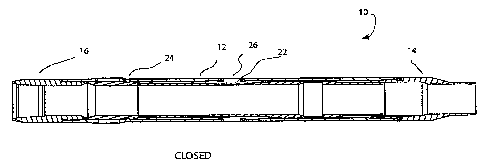
[012] Fig. 1 is an exemplary embodiment of a downhole tool showing at least
one
aspect of the invention in the closed position.
[013] Fig. 2 is an exemplary embodiment of a downhole tool showing at least
one
aspect of the invention in the open position.
[014] Fig. 3 is a diagrammatic view of a system according to at least one
aspect of
the present invention.
[015] Similar reference characters denote corresponding features consistently
throughout the attached drawings.
is DETAILED DESCRIPTION
[016] The present invention according to at least one aspect is to a downhole,
window tool 10 having a device for activating a lateral window on the tool in
preparation for well processes such as fracturing and production without
having to
run the tool out of the hole to change the mode of the tool.
[017] The downhole window tool 10 is designed to be installed on a drill
string 60
or similar device. As shown in Figure 3, a number of the tools 10 may be
installed
4

CA 02751967 2011-09-12
and separated a large distance apart by spacers 62 or the like of sufficient
length so
that when installed the opening 18 of each window tool 10 aligns with an
opening 64
of the well casing 66. While only two tools are shown, any number of tools may
be
used. The drill string and components may be connected at the top to a tank 68
at
a location above the surface to contain produced fluids.
[018] As shown in Figures 1 and 2, an individual downhole, window tool may
comprise an outer housing 12, which is substantially tubular in shape. An
upper sub
16 and lower sub 14 may be connected at either end of the tool by threads,
screws,
shear pins or the like. The outer housing has an opening 18, which is
preferably
io formed as a number of slots or openings around the circumference of the
housing
but may be one continuous opening. The purpose of these openings is to allow
fluid
communication between an area within the housing and the area outside of the
housing when the opening 18 is uncovered by an internal sleeve 20. The
internal
sleeve is arranged to slide within the outer housing 12 between a closed
position as
shown in Figure 1 and an open position as shown in Figure 2. A stop 22 may be
installed in the outer housing 12 to control the distance that the internal
sleeve may
slide. The slide may be anchored by a button or detent 26 extending from the
slide
being located in the outer housing. The sleeve 20 below the lower surface of
the
slide will prevent the stop button from sliding out of the housing thus will
maintain
the stop in place. The ends of the stop may provide an upper and/or lower
limit to
the sliding motion of the sleeve. The stop may alternatively be used to
connect the
5

CA 02751967 2011-09-12
opposite ends of the housing, but preferably the housing is made of a one
piece unit
with the stop installed between the housing and the sleeve.
[019] In the preferred embodiment, the sleeve is arranged within the outer
housing
to slide between the closed position and the open position. To prevent
unintentional
operation of the sleeve, the sleeve may be pinned in the closed position by a
shear
pin 24 or the like. The shear pin will shear under a preselected pressure to
allow
the sleeve to slide to the open position. The present design as will be
discussed
hereinunder further prevents unintentional opening by reducing the number of
pressure surfaces within the window tool that could be acted upon to open the
1o window (i.e., "activate the sleeve"). Previous designs show a ball valve
dropped
through the tool to plug a valve seat to operate the sleeve movement under
fluid
pressure. Because the ball is of a very limited size compared to the diameter
of the
housing, the valve seat itself blocks a great deal of flow through the tool,
which
could potentially cause the sleeve to prematurely move. Additionally, the
valve seat
restriction acts to restrict the total amount of flow through the tool from
lower window
tools and thus may reduce the production flow through the drill string.
[020] The present invention by contrast uses a removable bridge plug 30 or
dart to
activate the tool. A recess, internal flange or abutment in the sleeve may be
used to
capture the plug or dart when installed. The plug or dart acts to block flow
through
the tool allowing pressure to build up until it exceeds the shear point of the
shear pin
holding the sleeve in place. The fluid pressure then acts to move the sleeve
away
from the window 18 to allow communication through the window to an outer zone
or
6

CA 02751967 2011-09-12
further tubing, etc. The walls of the recess retaining the plug cause the
sleeve to
travel with the plug instead of allowing the plug to slide along the sleeve.
The walls
allow forces to be transferred from the plug (or dart) to the sleeve.
[021] The use of a dart or bridge plug also allows easier selection of the
tool on
which to operate. A casing collar locator tool (T CU) or similar device may be
used
to track the depth of a tool or portion of a tool. By tracking the depth of
windows in
the down hole and the depth of the bridge plug or dart, the dart may be place
precisely into a desired window tool and inflated or otherwise fixed in place
in a
particular window tool. Subsequent pressurization of the interior of the
window tool
io from the surface will cause the pressure to act on the bridge plug or dart
and thus
on the sleeve, shearing the pin 24 and moving the sleeve to the open position.
The
sleeve will then stay open until processing is completed and the tool removed
to the
surface. The plug or dart may be removed if flow is desired to a location
below the
tool, such as to a lower tool using a known bridge plug or dart removal tool.
[022] While this invention has been described as having a preferred design, it
is
understood that it is capable of further modifications, uses and/or
adaptations of the
invention following in general the principle of the invention and including
such
departures from the present disclosure as come within the known or customary
practice in the art to which the invention pertains and as maybe applied to
the
central features hereinbefore set forth, and fall within the scope of the
invention and
the limits of the appended claims. It is therefore to be understood that the
present
7

CA 02751967 2011-09-12
invention is not limited to the sole embodiment described above, but
encompasses
any and all embodiments within the scope of the following claims.
8

Representative Drawing
A single figure which represents the drawing illustrating the invention.
Administrative Status

2024-08-01:As part of the Next Generation Patents (NGP) transition, the Canadian Patents Database (CPD) now contains a more detailed Event History, which replicates the Event Log of our new back-office solution.

Please note that "Inactive:" events refers to events no longer in use in our new back-office solution.

For a clearer understanding of the status of the application/patent presented on this page, the site Disclaimer , as well as the definitions for Patent , Event History , Maintenance Fee  and Payment History  should be consulted.

Event History

Description Date
Time Limit for Reversal Expired 2015-09-14
Application Not Reinstated by Deadline 2015-09-14
Deemed Abandoned - Failure to Respond to Maintenance Fee Notice 2014-09-12
Letter Sent 2013-06-07
Inactive: Correspondence - Transfer 2013-05-01
Inactive: Office letter 2013-03-07
Inactive: Correspondence - Transfer 2012-11-30
Inactive: Office letter 2012-08-14
Inactive: Single transfer 2012-07-23
Inactive: Single transfer 2012-07-04
Application Published (Open to Public Inspection) 2012-03-10
Inactive: Cover page published 2012-03-09
Inactive: IPC assigned 2012-02-20
Inactive: First IPC assigned 2012-02-20
Inactive: Filing certificate - No RFE (English) 2011-09-23
Application Received - Regular National 2011-09-23

Abandonment History

Abandonment Date Reason Reinstatement Date
2014-09-12

Maintenance Fee

The last payment was received on 2013-09-06

Note : If the full payment has not been received on or before the date indicated, a further fee may be required which may be one of the following

  • the reinstatement fee;
  • the late payment fee; or
  • additional fee to reverse deemed expiry.

Patent fees are adjusted on the 1st of January every year. The amounts above are the current amounts if received by December 31 of the current year.
Please refer to the CIPO Patent Fees web page to see all current fee amounts.

Fee History

Fee Type Anniversary Year Due Date Paid Date
Application fee - standard 2011-09-12
Registration of a document 2012-07-04
Registration of a document 2012-07-23
MF (application, 2nd anniv.) - standard 02 2013-09-12 2013-09-06
Owners on Record

Note: Records showing the ownership history in alphabetical order.

Current Owners on Record
TEAM OIL TOOLS, L.P.
Past Owners on Record
DONALD W. TINKER
MICHAEL T. SOMMERS
Past Owners that do not appear in the "Owners on Record" listing will appear in other documentation within the application.
Documents

To view selected files, please enter reCAPTCHA code :


To view images, click a link in the Document Description column (Temporarily unavailable). To download the documents, select one or more checkboxes in the first column and then click the "Download Selected in PDF format (Zip Archive)" or the "Download Selected as Single PDF" button.

List of published and non-published patent-specific documents on the CPD .

If you have any difficulty accessing content, you can call the Client Service Centre at 1-866-997-1936 or send them an e-mail at CIPO Client Service Centre.

({010=All Documents, 020=As Filed, 030=As Open to Public Inspection, 040=At Issuance, 050=Examination, 060=Incoming Correspondence, 070=Miscellaneous, 080=Outgoing Correspondence, 090=Payment})


Document
Description 
Date
(yyyy-mm-dd) 
Number of pages   Size of Image (KB) 
Description 2011-09-11 8 256
Claims 2011-09-11 7 137
Drawings 2011-09-11 2 27
Abstract 2011-09-11 1 23
Representative drawing 2012-02-22 1 6
Filing Certificate (English) 2011-09-22 1 156
Reminder of maintenance fee due 2013-05-13 1 114
Courtesy - Certificate of registration (related document(s)) 2013-06-06 1 103
Courtesy - Abandonment Letter (Maintenance Fee) 2014-11-06 1 172
Correspondence 2012-08-13 1 17
Correspondence 2013-03-06 1 17