Note: Descriptions are shown in the official language in which they were submitted.
79350-250D CA 02752135 2012-07-31
METHOD OF RETREIV1NG A MOBILTY ENHANCED FORMATIONFLUID SAMPLE
BACKGROUND
Cross-Reference to Related Applications
[0001] This application is a divisional application of
Canadian Patent Application
No. 2,601,495 filed on September 12, 2007 and claims priority from therein.
Field of the disclosure
[0002] This disclosure generally relates to oilfield exploration.
More particularly,
this disclosure relates to techniques for drawing fluids from a formation into
a downhole
tool.
Background of the Disclosure
= [0003] "Heavy oil" or "extra heavy oil"
are terms of art used to describe very viscous
crude oil as compared to "light crude oil". Such highly viscous crude oils are
often
referred to as "low mobility formation fluids". Large quantities of heavy oil
can be found
in the Americas, in particular, Canada, Venezuela, and California.
Historically, heavy oil
was less desirable than light oil. The viscosity of the heavy oil makes
production very
difficult. Heavy oil also contains contaminants and/or many compounds which
make
refinement more complicated. Recently, advanced production techniques and the
rising
price of light crude oil have made production and refining of heavy oil
economically
feasible. 1
CA 02752135 2011-09-09
79350-250D
[0004] Heavy oil actually encompasses a wide variety of very viscous crude
oils.
Medium heavy oil generally has a density of 903 to 906 kg-m-3, an API
(American
Petroleum Institute) gravity of 25 to18 , and a viscosity of 10 to 100 mPa-s.
It is a
mobile fluid at reservoir conditions and may be extracted using for example
cold heavy
oil production with sand (CHOPS). Extra heavy oil generally has a density of
933 to
1,021 kg-m-3, an API gravity of 20 to 7 , and a viscosity of 100 to 10,000
mPa-s. It is a
fluid that can be mobilized at reservoir conditions and may be extracted using
heat
injection techniques, such as cyclic steam stimulation, steam floods, and
steam assisted
gravity drainage (SAGD) or solvent injection techniques such as vapor assisted
extraction
(VAPEX). Tar sands, bitumen, and oil shale generally have a density of 985 to
1,021
kg-m-3, an API gravity of 12 to 7 , and a viscosity in excess of 10,000 mPa-
s. They are
not mobile fluids where the formation temperature is approximately 10 C (in
Canada),
and must be extracted by mining. Hydrocarbons with similar densities and API
gravities,
but with viscosities less than 10,000 rnPa-s can be partially mobile where the
formation
temperature is approximately 50 C (in Venezuela).
[0005] Various tools and techniques have been proposed to increase the
mobility of a
highly viscous formation fluid, such as heavy oils and bitumen, thereby to
obtain a
sample. The proposed techniques typically employ a single approach, such as
coring
into, applying heat to, or injecting a fluid into a formation in an attempt to
retrieve a
sample of the highly viscous formation fluid, regardless of the particular
characteristics
of the particular formation or viscous fluid. Tools which perform these
techniques
further typically execute a predetermined process, again without taking into
account the
characteristics of the particular formation makeup or fluid.
2
CA 02752135 2012-07-31
7.9350-250D
SUMMARY
[0006] Some embodiments of this disclosure may provide tools and methods
which expedite the sampling of formation fluids, and particularly, although
not
exclusively, the sampling of high viscosity hydrocarbons or low mobility
fluids.
[0007] According to one aspect of this disclosure, a method of retrieving a
formation fluid from a formation adjacent a borehole wall is disclosed which
includes
estimating at least one of a permeability of the formation and a viscosity of
the
formation fluid or a fluid mobility in the formation. A first tool is selected
based on the
estimation, the first tool being selected from one of a heating and sampling
tool, an
injection and sampling tool, and a coring tool. An attempt to retrieve a
formation fluid
sample from the formation is then made with the first tool, and a formation
fluid
sample is retrieved from the formation.
[0007a] According to another aspect of this disclosure, there is provided a
method of retrieving a formation fluid sample from a formation adjacent a
borehole
wall, the method comprising the steps of: lowering a downhole tool into the
wellbore,
selecting a suitable formation fluid sample retrieval process on the basis of
an
estimate of a downhole parameter related to a mobility of the formation fluid;
performing a first formation fluid sample retrieval process according to the
selected
formation fluid sample retrieval process, the first formation fluid sample
retrieval
process including, prior to retrieving the formation fluid sample, performing
an
operational step that attempts to increase the mobility of the formation
fluid; analyzing
the formation fluid sample so as to acquire a measured value of at least one
downhole parameter related to the mobility of the sampled formation fluid;
changing
the formation fluid sample retrieval process based on the measured value of
the at
least one, mobility-related downhole parameter; performing a second formation
fluid
sample retrieval process according to the changes made to the formation fluid
sample retrieval process, the second formation fluid sample retrieval process
including performing another operational step that increases the mobility of
the
3
CA 02752135 2012-07-31
9350-250D
formation fluid; and retrieving the formation fluid sample from the formation
with the
tool.
[0008] According to additional aspects, a method of retrieving a formation
fluid
from a formation adjacent a borehole wall is provided in which a tool is
lowered into
the wellbore. A first retrieval process is initiated in which the first
retrieval process
includes attempting to increase the mobility of the formation fluid. At least
one
down hole parameter related to the mobility of the fluid is then measured, and
the first
retrieval process is changed based on the measured downhole parameter. A
second
retrieval process is then initiated, in which the second retrieval process
includes
increasing the mobility of the formation fluid. The fluid sample is then
retrieved from
the formation with the tool.
3a
CA 02752135 2011-09-09
79350-250D
[0009] Additional objects and advantages of this disclosure will become
apparent to
those skilled in the art upon reference to the detailed description taken in
conjunction
with the provided figures.
BRIEF DESCRIPTION OF THE DRAWINGS
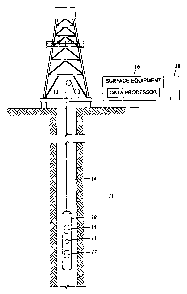
[0010] FIG. 1 is a schematic representation of a system deployed via a
wireline in a
wellbore and coupled to surface equipment;
[0011] FIG. 2 is a high level schematic diagram of a coring tool including
means for
preserving core samples;
[0012] FIG. 3 is a schematic illustration of a sampling tool deployed downhole
and
being used according to some of the methods of this disclosure;
[0013] FIG. 4 is a detailed schematic illustration of a probe assembly of a
tool having
a heating element mounted on a drill shaft;
[0014] FIG. 5 is a schematic broken perspective of a packer portion of a tool
having a
guarded sampling packer around a drill shaft;
[0015] FIG. 6 is a schematic illustration of a sampling tool capable of
enhancing the
mobility of a reservoir fluid by delivering heat from a heat source;
[0016] FIG. 7 is a schematic illustration of a packer portion of a tool
capable of
enhancing the mobility of a reservoir fluid by delivering heat with one or
more
electrodes;
4
CA 02752135 2011-09-09
79350-250D
[0017] FIG. 8 is a side elevation view of pressure and temperature gauges
attached to
injection and production flowlines;
[0018] FIG. 9 is a schematic showing one embodiment of a testing tool capable
of
sealing wellbore intervals of various lengths; and
[0019] FIGS. 10A-C show a schematic flowchart illistrating a method of
retrieving a
fluid sample from a formation.
DETAILED DESCRIPTION
[0020] Techniques for retrieving formation fluid are disclosed herein.
According to
one method disclosed herein, a characteristic of the formation (such as
permeability)
and/or of the fluid (such as viscosity) is estimated. Based on the estimation,
a fluid
retrieving tool, such as a heating and sampling tool, an injection and
sampling tool, or a
coring tool, is selected. A downhole tool may carry multiple retrieving tools
so that the
desired tool may be selected. According to an additional technique, a downhole
tool may
initiate a retrieval process, measure a downhole parameter related to the
mobility of the
fluid, and change the first retrieval process based on the measured downhole
parameter.
Additionally, a second retrieval process may be initiated to increase the
mobility of the
formation fluid.
[0021] Turning now to Fig. 1, the basics of a reservoir exploration (borehole
logging)
system are shown. A borehole tool or sonde 10 is shown suspended in a borehole
14 of a
formation 11 by a cable 12, although it could be located at the end of coil
tubing, coupled
5
CA 02752135 2011-09-09
79350-250D
to a drill-pipe, or deployed using any other means used in the industry for
deploying
borehole tools. Cable 12 not only physically supports the borehole tool 10,
but typically,
signals are sent via the cable 12 from the borehole tool 10 to surface located
equipment
16. In addition, cable 12 is often used to provide electrical power from the
surface to the
borehole tool 10. The surface located equipment 16 may include a signal
processor, a
computer, dedicated circuitry, or the like which is well known in the art.
Typically, the
equipment/signal processor 16 takes the information sent uphole by the
borehole logging
system 10, processes the information, and generates a suitable record such as
a display
log 18 or the like. Suitably, the information may also be displayed on a
screen and
recorded on a data storage medium or the like.
[0022] The borehole tool 10 may include at least a first
fluid retrieval tool 15 which
is capable of retrieving fluid from the formation. In the illustrated
embodiment, the
borehole tool 10 also includes a second fluid retrieval tool 17, which is also
capable of
retrieving fluid from the formation. The first and second fluid retrieving
tools 15, 17
either include their own controllers or may be operably coupled to a central
control
system 13 which may include a processor (not shown). Alternatively and/or
additionally,
the retrieving tools 15, 17 are communicably coupled to the surface controller
16.
[0023] While the present disclosure is directed to techniques
for retrieving formation
fluid samples, those techniques may be carried out by any one or more of a
variety of
= retrieving tools, such as a coring tool, a heating and sampling
tool, or an injection and
sampling tool. In one example, a coring tool, a heating and sampling tool, or
an injection
and sampling tool may be selectively included in the downhole tool 10 based on
an
estimate of one of the permeability of the formation 11, the viscosity of the
formation 11,6
CA 02752135 2011-09-09
79350-250D
and the mobility of the fluid in the formation 11. The estimate of the
mobility may be
derived from logs or other formation data of the current well, logs or other
formation data
from other wells in the same reservoir, analysis of the cuttings obtained
during the
drilling of the current well or other wells in the same formation, or a
reservoir model, if
available. In another example, two or more of a coring tool, a heating and
sampling tool,
and an injection and sampling tool may be part of the downhole tool 10. One of
the
coring tool, the heating and sampling tool, and an injection and sampling tool
may be
selected downhole based on an estimate of the mobility of the fluid performed
by the
other of the coring tool, the heating and sampling tool, and an injection and
sampling
tool. It will be appreciated by those skilled in the art that by taking into
account the
characteristics of the particular formation or fluid to be sampled in the
selection of the
retrieving tool(s) implemented into the tool 10, the probability that at least
a component
of the downhole tool 10 expedites the sampling of the formation is increased.
[0024] One of the first and second fluid retrieving tools 15, 17 may be
provided as a
coring tool, such as the exemplary coring tool 30 is illustrated in FIG. 2.
The coring tool
30 includes a coring bit 32 for obtaining core samples from the formation. The
coring bit
32 may be surrounded by an annular seal 34 and may be arranged to swivel from
horizontal to vertical so that core holders containing cores (not shown) can
be stored in a
vertical storage rack 36. Once stored in the storage rack(s), the cores may be
brought to
the surface for analysis. Alternatively, the cores may be ground with a
grinder 33 to
obtain access to the formation fluid deposits, with the residual formation
fluid being
extracted and stored in a sampling chamber 38.
[0025] In other exemplary embodiments, the formation fluid may be extracted
from
7
CA 02752135 2011-09-09
79350-250D
the core(s) using one or more of a plurality of methods. For example, a
heating unit 35
may engage or receive the core(s) and be adapted to reduce the viscosity of
the heavy oil
by increasing the temperature in and/or around the core. The heating unit 35
may
produce heat using one or more of a chemical, resistive, radiant, and
conductive
apparatus, but may include others know in the art.
[0026] The core(s) and/or the formation fluid, whether ground or not, may also
be
tested for one of the many propertied or parameters discussed herein. For
example, the
core may undergo resistivity measurements. In order to obtain the desired
parameter
information, the coring tool 30 may include one or more sensors 39 that may be
disposed
proximate the sample chamber 38, the heating unit 35, and the storage rack,
among
others.
[0027] The coring tool 30 may be used to advantage for retrieving formation
fluid
from a formation adjacent of a wellbore. In some cases, the fluid is extracted
downhole
and stored in a sampling chamber 38, as mentioned above. Further, the coring
tool 30
may seal the captured cores using methods known in the art. Still further, the
coring tool
30 may include a refrigeration unit (not shown) to preserve the core or fluid
samples for
example by minimizing the mobility of the fluid trapped in cores. Thus, the
core may be
brought at the earth surface where the trapped fluid may be flushed and
analyzed.
[0028] Instead of coring, the fluid retrieving tools may use injection to
improve the
mobility of the formation fluid while in the formation. Such injection and
sampling tools
may inject one or more of chemicals that may generate heat by reacting
together,
chemical that may react with the formation fluid (e.g. air, oxygen), oil,
steam, water, hot
8
CA 02752135 2011-09-09
79350-250D
fluid, solvent (e.g. carbon dioxide, nitrogen, methane, polar liquid
hydrocarbon). Either
one of the fluid retrieving tools 15, 17 may be selectively provided as an
injection
sampling tool.
[0029] An exemplary injection sampling tool 50 that uses drilling means for
injecting
fluid is illustrated in FIG. 3 positioned in a borehole 52 9f a formation 54.
The tool 50
includes two probe assemblies 56, 58 which are extendable out of the tool
toward the
borehole wall 52a. Each probe assembly 56, 58 includes an elastic packer 56',
58' that
surrounds a respective drilling means 60, 62. = Suitable packers include
packers as shown
in U.S. Patent Application Pub. No. 2006/0000606 or U.S. Patent Application
Pub. No.
2005/0279499. Alternatively or additionally, inflatable straddle packers (not
shown) may
be used that are able to isolate portions of the borehole 52. A suitable
drilling means may
be that found in the Cased Hole Dynamics Tester (CHDT) tool (see, e.g.,
"Formation
Testing and Sampling through Casing", Oilfield Review, Spring 2002). It should
be
noted however that the tool 50, unlike the CHDT tool described above, may be
used in an
uncased borehole. The drilling means each include a drill bit 60a, 62a, a
respective drill
shaft 60b, 62b, and a flowline 60c, 62c. The flowline 60c, 62c may extend
through the
shafts 60b, 62b, as shows, but may have various other configurations. For
example, the
flowlines 60c, 62c may be disposed on a separate probe assemblies from the
drilling
means 60, 62 and/or may have an inlet disposed near the packers 56', 58'.
[0030] The flowlines 60c, 62c are coupled to respective pumps 64, 66. The
pumps
64, 66 are coupled by respective flowlines and valves to fluid
containers/sample
chambers 68a, 68b and 70a, 70b, respectively. Optional fluid analyzers (FA)
72a, 72b
may be coupled to flow line operatively associated with the pumps 66, 64 and
are
9
CA 02752135 2011-09-09
79350-250D
capable, among other things, of monitoring a property of the fluids drawn at
the probes
58, 56 and/or monitoring a property of the fluids injected into the formation
54. The fluid
analyzers 72a, 72b measure a fluid property in situ and may comprise one or
more of a
fluorescence sensor, an optical sensor, a pressure sensor, a temperature
sensor, a
resistivity and/or a conductivity sensor. Alternatively or additionally, the
density and/or
the viscosity of the fluid in the flow line may be measured by one or more
sensors known
in the art, including sensor(s) based on acoustic, vibrating mechanical
object, or nuclear
magnetic resonance (NMR) measurement principles. Electronics 74 are preferably
provided to control the valves, the pumps and the drilling means, to
communicate with
surface equipment, and/or to analyze the contents of the fluid containers,
etc, in
conjunction with the optional fluid analyzers 72a-b and/or other sensors (not
shown).
[0031] In operation, one or both of the probes 56, 58 may be extended out of
the tool
to engage the borehole wall 52a, and preferably seal one or more locations
along the
borehole wall. The drilling means 60, 62 are activated such that the drill
bits 60a, 62a
drill holes 54a, 54b through the isolated locations of the borehole wall 52a
into the
formation 54. When the tool 50 is so deployed, the flowlines 60c, 62c are in
fluid
communication with the holes 54a, 54b in the formation 54, and essentially
sealed to the
fluids in the wellbore. In one exemplary embodiment, the pump 64 may be
activated so
that the contents of the fluid containers 68a and 68b are pumped into the
flowline 60c,
through the probe 60 and into the hole 54a.
[0032] In other exemplary embodiments, the tool 50 may only include one
drilling
means and/or only one sampling means, which may or may not be disposed around
the
same probe assembly. For example, the tool 50 may inject fluid into the
formation
10
CA 02752135 2011-09-09
79350-250D
through a first probe assembly and retrieve the formation fluid through the
same
assembly. In short, the tool 50 is not limited to the embodiment disclosed
above, but may
have any other configurations using one or more of the components described
above.
[0033] In one embodiment, the tool 50 uses a chemical reaction to generate a
hot
injection fluid. The contents of the containers 68a and 68b may be chosen so
that they
react with each other exothermically as disclosed in commonly¨owned U.S.
Publication No. 2008/0066904. The hot fluid
enters the porous formation 54 and mobilizes formation fluids in its vicinity.
Pump 66 is
then activated to extract mobilized formation fluid from the hole 54b. The
fluids
extracted by pump 66 may be sent through the optical analyzer 72a to monitor
one or
more characteristics of the fluid.
[0034] Instead of using a chemical reaction, the tool 50 may generate in-situ
(controlled) combustion by pumping air, oxygen, or a mixture thereof into one
of the
holes 54a, 54b. The injection rate of air or oxygen may be varied by the tool,
for
example to control the combustion rate. In addition, steam or water may also
be pumped
in the first hole for controlling the combustion front temperature. The
combustion may
consume some of the in-situ oil and produce heat, combustion gases and water
vapor.
Alternatively, or additionally, a hydrocarbon may be mixed into and injected
with the air
or oxygen. The injected mixture may also sustain a combustion process. The
ratio of
oxygen to hydrocarbon may be controlled so that the chemical composition of
the
mixture is within the combustion boundaries. The combustion products may
reduce the
viscosity of the oil and serve to drive the oil ahead of the combustion front,
such as
toward the second drilled hole where it can be pumped into the tool.
11
CA 02752135 2011-09-09
79350-250D
[0035] In a further alternative, the tool 50 may include a container 70a
filled with a
hot fluid or steam which optionally is generated downhole by heating elements
(not
shown) or by any technique described in U.S. Publication No. 2008/0066904.
Alternatively, the hot fluid or steam may be generated uphole at the surface.
The hot fluid
is injected into the hole 54b and mobilized formation fluid may then be
extracted from
the hole 54b by reversing the pump 66. The fluids extracted from the hole 54b
may then
be analyzed in the fluid analyzer (FA) 72a over a period of time in order to
determine
whether they should be stored or dumped. For example, fluid initially
extracted from the
hole 54b may contain a significant amount of the injected fluid and that fluid
may either
be dumped into the borehole or re-injected into the formation. After a period
of time, the
fluid being extracted may be substantially pure formation fluid (defined
herein as 90% or
more pure). If it is desirable to sample the substantially pure formation
fluid, that fluid
may be fed to a previously empty container, e.g., container 70b.
[0036] The same tool 50 may further be used in a non-thermal process for
retrieving
fluid from a formation. For example, one of the containers 68a-b, 70a-b of the
tool 10
may contain a mobility enhancer, such as by way of example and not limitation
a
miscible solvent such as a halogenated or otherwise polar normally liquid
hydrocarbon,
carbon dioxide, and most preferably a chlorinated solvent in which asphaltenes
dissolve.
Other containers may be used to collect mobilized formation fluid samples at
different
= formation locations. For example, tool 50 can be set in the borehole and
used to drill
through the borehole wall into the formation to generate hole 54a. A mobility
enhancer
stored in container 68a can be injected into hole 54a through use of pump 64.
After a
period of time, if desired, pump 64 can be reversed, and mobilized formation
fluid can be
12
CA 02752135 2011-09-09
79350-250D
collected via hole 54a and stored in container 68b or dumped as desired, for
example,
based on information collected by the fluid analyzer (FA) 72b. At the same
time, or at
some other time earlier or later, the second pump 66 can be activated if
desired in order to
pull mobilized formation fluids from the formation at a second location
removed from
hole 54b via the probe 58. Again, these fluids can be stored or dumped as
desired. After
the desired sampling is completed, tool 50 can be moved to another location,
and one or
both of pumps 64 and 66 can be activated to pull yet additional formation
fluids from the
formation which may be have been mobilized via the injection of the mobility
enhancer
into hole 54a.
[0037] It can be appreciated that the tool 50 may be operated according to one
or
more operating parameters. These parameters include, but are not limited to,
pumping
rate, pumping differential pressure, injection rate, injection volume,
injection fluid or
medium, injection ratio of different fluids, drilled hole length and/or
spacing. The value
of the operating parameters may be varied between one formation and another,
for
example based on one of the mobility of the fluid in the formation, the
permeability of
the formation, or the viscosity of the formation fluid. These properties may
be estimated
from measurements performed before the tool 10 is lowered in the wellbore or
by
components of the tool 10. The values of the operating parameters of the tool
50 may be
adjusted according to the latest or otherwise most reliable estimate of these
properties,
amongst other, as further detailed with respect to FIGS. 10A, 10B, 10C.
[0038] Instead of injecting, the fluid retrieving tools may use heat to
improve the
mobility of the formation fluid while in the formation. Such thermal sampling
tools may
use one or more of several heating sources, such as radio frequency (RF)
heating, hot
13
CA 02752135 2011-09-09
79350-250D
fluid, resistive heating, conductive heating, ultrasonic heating, or
exothermic chemical
reaction. Either one of the fluid retrieving tools 15, 17 may be selectively
provided as a
thermal sampling tool.
[0039] Another embodiment of a sampling tool having an extendable drill means
is
illustrated in FIG. 4. The sampling tool 110 includes a lrating element 127
provided
about a shaft 125. The heating element may comprise a resistive wire wound up
around
the shaft 125. The drill bit and shaft are surrounded by a seal 119 and a seal
backing
plate 121. A drill bit 124 extends out of the tool 110 while drilling a hole
129 through the
mud cake on the borehole wall 52a into the formation 54. The drill bit may be
piloted by
the tool 110 using a shaft guide 130. It is also contemplated herein that the
heating
element 127 could be configured and activated in many ways. For example, the
heating
element may be an RF heating element, a resistive heating element, an ultra-
sonic heating
element, and/or a conductive heating element, and may not be attached to the
drill shaft
125, but may be a wholly separate component. Accordingly, any of the
contemplated
configuration and activation methods may be implemented in various
configurations of
the before described tools. Some of these methods will be expanded upon below.
[0040] According to another alternate embodiment, the heating element 127 may
comprise an antenna or coil which emits electromagnetic radiation. It should
be noted
that the frequency of the electromagnetic radiation can vary from kHz to GHz.
The
electromagnetic radiation power may be partially absorbed by the formation
hydrocarbon
fluid, connate water, or a fluid injected in the formation 54 by the tool 110.
The
frequency of the electromagnetic radiation may be selected by considering the
following
elements. The power absorption mechanism is typically dipole relaxation. Thus,
the
14
CA 02752135 2011-09-09
79350-250D
power absorption characteristics usually vary from fluid to fluid. The power
absorption
characteristics of a fluid are related to the complex electric permittivity of
this fluid,
which can be measured in a laboratory. The absorption maxima occur at
approximately
the frequencies corresponding to the maxima of the complex part of the
permittivity.
Also, it should be noted that the penetration of the electromagnetic wave
decreases with
increasing frequency, and that the absorption coefficient is approximately the
reciprocal
of the penetration depth and decreases as the frequency decreases. In some
cases, the
power absorption may be significant at frequencies coincident with an
absorption
frequency of a molecular mode of motion other than dipole relaxation.
[0041] In one example the coil is wound up around the shaft and generates
current
loops in the formation 54 that encircle the hole 129. According to another
alternate
embodiment, the heating element 127 May be replaced by an acoustic transducer
(e.g.
ultrasound) which stimulates the oil or adjacent fluid either directly or
indirectly. For
example, the ultrasonic transducer 127 may vibrate the drill bit 124 axially
and generate
acoustical waves in the formation 54.
[0042] According to one exemplary method, the tool 110 may be used to drill a
hole
129 in the formation 54. The mobility of the oil in the vicinity of the hole
129 may be
enhanced by delivering heat, and or vibrations to the formation 54, utilizing
the element
127. For example, the heating element 127 can be activated through electrical
control of
the tool 110 and used as a mobility enhancer in order to expedite flow of
formation
fluids. As will be appreciated by those skilled in the art, formation fluids
can flow
through an annulus between the drill shaft 125 and the hole 129 into the tool
110. The
15
CA 02752135 2011-09-09
79350-250D
seal 119 is preferably pressed against the formation for sealing the annulus
from fluid in
the wellbore.
[0043] The probe or packer, as mentioned is any of the forgoing embodiments,
may
further include a guard for preventing contamination of the fluid samples
retrieved from
the formation. As illustrated in FIG. 5, a guarded probe l20 may be provided
having a
centrally positioned drilling element 122 which is surrounded by an annular
sampling
conduit 124. The drill and the sampling conduit are surrounded by a compliant
isolation
element 126 which serves to prevent hydraulic communication between the
annular
sampling conduit 124 and the annular guard conduit 128, and an outer isolation
element
130, both of which are shown mounted on a backing plate 132. A hydraulic
circuit which
can be adapted to control the guarded probe 120 is shown in published U.S.
Patent
Application Pub. No. 2006/0042793.
[0044] Referring now to FIG. 6, another sampling tool capable of delivering
heat for
enhancing formation fluid mobility is described in further detail. The tool
150 is
conveyed downhole with a wireline cable 152. The tool 150 includes a sampling
system.
As shown, the sampling system may comprise at least an extendable probe 154
for
establishing a fluid communication between the formation 54 and the tool 150.
A
downhole pump 156 is hydraulically coupled to the probe 154 via a flowline
158. The
pump 156 may be used to advantage for lowering the pressure in the flowline
158 below
the formation pressure, while maintaining the pressure at the pump outlet
above the
wellbore pressure. Valves are communicatively coupled to a controller 160 and
are
selectively actuated to route the fluid to either dump into the borehole 52 or
to discharge
into a fluid container 162. The tool 150 may p.lso includes a drill bit 164
mechanically
16
CA 02752135 2011-09-09
79350-250D
coupled to a drill shaft 166. The drill shaft 166 is operated via a motor (not
shown) to
drill a hole 168 in the formation 54. The motor may be powered by a downhole
battery
170, or via the wireline cable 152, or a combination thereof. In these
embodiments, the
hole 168 may be used for delivering heat deeper into the formation 54, and
thus,
enhancing the oil mobility in a region adjacent to the sampling probe 154,
expediting
thereby the sampling process.
[00451 The tool 150 is configured for delivering heat to the formation 54 by
thermal
conduction. The tool 150 comprises a heat source 172. The heat source 172 may
be a
resistive heater powered by any of the current provided by the wireline cable
152 or the
battery 170, a chemical reactor where an exothermic chemical reaction is
conducted, or
some power electronics in the tool 150, for example the power electronics
powering the
pump 156. Optionally, the heat flow from the heat source 172 may be controlled
by
using a heat pump 174, thermally coupled to the heat source 172 and to the
drill shaft 166
via optional heat exchangers 176. The heat pump 174 may be communicatively
coupled
to the controller 160 that controls the heating process based on temperature
measurement(s) provided by one or more sensor(s) 178. Alternatively, the
measurements
of sensor(s) 178 may be telemetered to the surface via wireline cable 152,
where they can
be utilized by a surface controller or a surface operator for monitoring and
controlling the
heating and/or sampling process. In this embodiment, the drill shaft 166
preferably
comprises a portion made of a good thermal conductor (not separately shown),
for
example copper or aluminum. This thermal conductor may further comprise a
working
fluid, for example water, and may operate as a heat pipe. Heat generated at
the heat
source 172 may then be delivered to the formation 54 by following the
schematic path
17
CA 02752135 2011-09-09
79350-250D
shown by arrows 180a to 180f. The heat delivered to the formation increases
the
temperature of the oil in the formation. The temperature increase of the oil
translates into
a viscosity decrease and thus a mobility enhancement. The mobilized oil may be
sampled by probe 154 and stored in fluid container 162 and brought to surface,
for
example for further analysis. Alternatively, the tool 150 may be modified to
deliver heat
to the formation 54 by thermal convection.
[0046] Yet another alternative sampling tool 200 may propagate current or an
electromagnetic wave in the formation 54. As shown in FIG. 7, the tool 200 may
include
articulated pads 212a and 212b. These pads may be placed against the formation
54 by
the tool 200, using known deployment means, such as arms 211a and 211b,
respectively.
When not used, the pads are preferably recessed below the outer surface of the
tool, for
example in apertures 210a and 210b in the tool body. As shown, the pads may
include a
plurality of electrodes such as electrodes 213a, 214a on pad 212a and
electrodes 213b and
214b on pad 212b. In one embodiment, the electrodes on each pad may be kept at
the
same potential, a potential difference is applied between the group of
electrodes on one
pad and the group of electrodes on another pad. This potential difference may
be
constant or may vary with time, and is provided by an electrical power source
at surface
or in the tool 200. Thus, current flows between two or more pads, at least in
part in the
formation 54. In another embodiment, a potential difference is applied between
electrodes on a same pad. Thus, current flows between electrodes as desired.
In both
embodiments, the current may flow preferably in the invaded zone of the
formation,
especially if the mud filtrate has a better conductivity than the oil in the
formation. In
some cases, the current flow generates heat in the formation. The mobility
enhancer is
18
CA 02752135 2011-09-09
79350-250D
heat that is introduced into the formation by thermal conduction or thermal
convection if
fluids in the formation are displaced, for example when injection from the
tool is also
used.
[0047] The tool 200 is also provided with an extendable probe 220 for
establishing a
fluid communication between the tool and the formation. The probe may be
detachably
coupled to a backing plate 224 for facilitating the replacement thereof. The
probe 220
may be made of a resilient material, and may comprise an internal support 225
for
preventing defon-nation of the probe seal under pressure differential between
the wellbore
and the tool. The probe is also provided with a recess 221 and a port 222 for
the flow of
fluids into the tool when the probe is applied against the borehole wall. The
probe is
provided with a drilling means 223, for drilling a hole in the borehole wall.
The hole
may be used for facilitating the injection of fluids from the tool 200 or for
drawing
formation fluid into the tool 200 and capturing a sample. In particular, fluid
may be
injected in the formation for modifying locally the resistivity of the
formation and
improving the efficiency of the heating via pads 212a and/or 212b.
[0048] Although shown with electrodes, the pads 212a and 212b may
alternatively
comprise any of electromagnetic antenna(e), acoustic transmitter(s),
resistor(s) or other
element(s) for generating heat. Further, the heating pads can be configured
with one or
more inlets through which a hole is drilled into the formation. The inlet may
be in fluid
communication with the tool so that the formation fluid can be sampled. Also,
the
heating elements, or electrodes, on the pad are preferably arranged so that
the depth to
which the heat is able to penetrate into the formation is sufficient for
mobilizing a volume
of oil corresponding to the sampling requirements. The heating elements, or
electrodes,
19
CA 02752135 2011-09-09
79350-250D
on the pad are not limited to two per pad. Similarly, any number of pads may
be used
and the tool 200 is not limited to two pads.
[0049] Instead of electrodes, the tool 200 may include
induction coils to deliver
current to the formation by induction. Still further, the tool 200 may include
some other
energy source, such as an ultrasonic emitter, to generate heat in the
formation. Details on
these and other alternatives are provided in U.S. patent application
2008/0078581 filed on June 14, 2007.
[0050] Although various embodiments are discussed herein with
association to the
articulated arms 211a and 211b, and the pads 212a and 212b, it is contemplated
that
heating of the formation may be accomplished without the use of the arm and
pads. For
example, the various exemplary heating methods may be employed while the
heating
apparatus is in the tool or affixed to the tool. In addition, the heating
apparatuses need
not be extendable from the tool as long as heating of the formation is
accomplished. For
example, it is contemplated that the tool may include backup pistons 226 for
forcing the
heating apparatus(es) against the formation. It is similarly contemplated that
the heating
apparatus(es) do not abut the formation, but rather heat the wellbore fluid
disposed
between the heating apparatus(es) and the formation, as well as the formation
itself.
[0051] It should be noted that the heating and sampling tools
of FIGS. 4-7 may be
operated according to one or more operating parameters. These parameters
include, but
=
are not limited to, pumping rate, pumping differential pressure, amount of
heat emanating
the heating mechanism, amount of energy provided to the heating mechanism, and
distance the heating mechanism extends into the formation. The value of the
operating 20
CA 02752135 2011-09-09
79350-250D
parameters may be varied between one formation and another, for example based
on one
of the mobility of the fluid in the formation, the permeability of the
formation, and the
viscosity of the formation fluid. The values of the operating parameters of
the heating
tool may be adjusted according to the latest or otherwise most reliable
estimate of these
properties, amongst other, as further detailed with respect to FIGS. 10A, 10B,
10C.
[0052] It should be appreciated that the fluid retrieving tools of the present
disclosure
may be implemented, if desired, in combination. Thus, the first and second
fluid
retrieving tools 15, 17 of FIG. 1 may be operatively coupled in one device.
For example,
a coring tool may be combined with a sampling tool, or an injection tool, as
shown in
published U.S. Patent Application Pub. No. 2005/0284629. Another example is
further
detailed below with respect to FIG. 8.
[0053] An alternative sample tool 300 reduces oil viscosity by heating a small
volume of the formation near the wellbore using AC current, and may further
pressurize
the heated heavy oil by injecting fluid into the formation. As shown in FIG.
8, the
sampling tool 300 includes a probe 302 having two formation interfaces 304a,
304b
connected to different flowlines, which allow for injection of a buffer fluid
into the
formation from one interface 304a and retrieval of reservoir fluid from the
other interface
304b. Exemplary buffer fluids include nitrogen, carbon dioxide, and polar
fluids like
dibromoethane. The buffer fluid composition and/or the injected quantity of
buffer fluid
should be selected so that it does not stimulate asphaltene precipitation. An
electrode
may be associated with each interface 304a, 304b for generating an alternating
current
that heats the formation. Alternatively, electrodes may be positioned at
points along the
probe and oriented to propagate alternating current into the formation.
Pressure and
21
CA 02752135 2011-09-09
79350-250D
temperature gauges 306 may be attached to flowlines associated with the
interfaces 304a,
304b to monitor the differential pressure at the sand face, the drawdown
pressure, and the
local formation temperature, which may be used to interactively control the
process.
Additional details regarding the sampling tool 300 and alternatives are
provided in U.S.
patent application 2009/0008079.
[0054] While the foregoing exemplary sampling tools include the use of an
extendable probe having a seal, an alternative sampling tool 400 uses
expandable packers
to seal off sections of the borehole. As best shown in FIG. 9, the sampling
tool 400 is
built in a modular fashion, with telemetry/electronics module 454, packer
module 408,
downhole fluid analysis module 451, pump module 452, and carrier module 453.
Telemetry/electronics module 454 may comprise a controller 440, for
controlling the tool
operation, either from instructions programmed in the tool and executed by
processor
440a and stored in memory 440b, or from instruction received from the surface
and
decoded by telemetry system 440c. Controller 440 is preferably connected to
valves,
such as valves 410, 411, 412, 413, 414, 415 and 416 via one or more bus 490
running
through the modules of tool 400 for selectively enabling the valves.
Controller 440 may
also control a pump 430, collect data from sensors (such as optical analyzer
431), store
data in memory 440b or send data to surface using telemetry system 440c. The
fluid
analysis module 451 may include an optical analyzer 431, but other sensors
such as
resistivity cells, pressure gauges, temperature gauges, may also be included
in fluid
analysis module 451 or in any other locations in tool 400. Pump module 452 may
comprise the pump 430, which may be a bidirectional pump, or an equivalent
device, that
22
CA 02752135 2011-09-09
79350-250D
may be used to circulate fluid along the tool modules via one or more flow
line 480.
Carrier module 453 can have a plurality of cavities, such as cavities 450-1,
450-2, to 450-
n to either store samples of fluid collected downhole, or transport materials
from the
surface, as required for the operation of tool 400. Packer elements 402, 403,
404 and 405
are shown uninflated and spaced along the longitudinal axis of packer module
408.
Although not shown, the packers extend circumferentially around tool 408 so
that when
they are inflated they will each form a seal between the tool and the borehole
wall 52a.
[0055] Also shown on FIG. 9 are particle breaking devices 460, 461, or 462.
These
particle breaking devices could be focused ultrasonic transducers or laser
diodes. Particle
breaking devices are preferably used to pulverize sand, or other particles
passing into the
flow lines, into smaller size particle, for example, for avoiding plugging of
component of
the testing tool. These devices may use different energy/frequency levels to
target
various grain sizes. For example, particle breaking device 462 may be used to
break
produced sand during a sampling operation. In some cases, the readings of
downhole
sensor 431 will be less affected by pulverized particles than larger size
particles. In some
cases, pump 430 will be able to handle pulverized particles more efficiently
and will not
plug, leak or erode as fast as with larger size particles in the mud. Particle
breaking
devices may be used for other applications, such as transferring heat to the
flow line
fluid.
[0056] In operation, the tool 400 is positioned in the borehole and selected
packer
elements are inflated to isolate a portion of the borehole. Access into the
formation fluid
may further require perforation into the borehole wall, which may be achieved
using any
23
CA 02752135 2011-09-09
79350-250D
known perforation means. Fluid samples may then be retrieved and stored in one
or more
cavities 450-1, 450-2, 450-n.
[0057] It should be appreciated that the length of the portion of the wellbore
wall that
is isolated between two extended packers may be adjusted by selectively
inflating two of
the four packers of the tool 400. For example, a large length may be achieved
by
inflating packers 402 and 405, or a short length may be achieved by inflating
packers 403
and 404. The length of the isolated portion of the wellbore may be varied
between one
formation and another, in particular based on one of the mobility of the fluid
in the
formation, the permeability of the formation, and the viscosity of the
formation fluid.
Similarly, the tool 400 may comprise a plurality of probes (not shown) having
different
dimensions. One of the probes may be selectively extended towards the wellbore
wall.
[0058] In an alternate embodiment, one or more of the packer elements 402,
403, 404
and 405 may be movable relative to the tool 400. This embodiment provides the
added
benefit of adjusting the relative spacing of the packers to enable optimal
fluid
communication with the formation and/or optimize sampling. Additional details
of the
various embodiments and features of the tool 400 are provided in U.S. patent
application
2008/0066535 filed on March 29, 2007.
[0059] According to certain aspects of the present disclosure, one or more
characteristics of the formation and/or the fluid are estimated to select a
suitable retrieval
method and apparatus. The characteristics of the formation and/or fluid are
monitored
and operation of the selected method may be altered based on that feedback.
24
CA 02752135 2011-09-09
79350-250D
Additionally or alternatively, a second retrieval method or apparatus may be
selected
based on the feedback, in which case the first retrieval method is ended and
the second
retrieval method is initiated. A downhole tool may include apparatus for
carrying out
both the first and second retrieval methods. For example, a single device may
include the
first retrieving tool 15, which may comprise a first type of retrieving tool,
and the second
retrieving tool 17, which may be a second, different type of retrieving tool.
Such a
device would allow the first and second sample methods to be performed without
tripping
the device.
[0060] An exemplary method 500 of retrieving a formation fluid is illustrated
in the
flow chart presented at FIGS. 10A, 10B and 10C. Referring to FIG. 10 A, the
method is
initiated at block 501 by collecting prior information. In one example, some
knowledge
of the reservoir hydrocarbon (e.g. viscosity) and/or the formation rock (e.g.
permeability)
to be sampled may be available from various sources, such as logs, formation
data or
cutting analysis of the current well; logs, formation data or cutting analysis
of from other
wells proximate of the current well; a reservoir model, etc. This information
may be
interpreted to determine relevant reservoir characteristics. The reservoir
characteristics
preferably include one of an estimated mobility of the fluid in the formation
to be
sampled, an estimated viscosity of the fluid to be samples and an estimated
permeability
of the formation to be sampled. However, other reservoir characteristics may
also be
determined from the prior information. The determined reservoir
characteristics are sent
to the model builder 514 of FIG. 10C.
[0061] Additional data may also be sent to the model builder 514. Additional
data
may include information about the economics of oil production, such as the
retail price of
25
CA 02752135 2011-09-09
79350-250D
oil, the availability of refinery plant close to the well, etc. The
information collected by
the model builder may be used for generating recommendations about the
sampling
process upon request, as further detailed below.
[0062] In one example, the prior information may be used, e.g. by the model
builder
514, to guide the selection of the most appropriate meth9dology for sampling,
or in other
words, to guide the selection of retrieval tools/methods. In particular, if an
oil having an
estimated viscosity in the range between around 100 and around 1,000 mPa.s is
to be
retrieved, a retrieval tool may comprise a heating and sampling tool only. If
an oil having
an estimated viscosity in the range between around 1000 and around 10,000
mPa.s is to
be retrieved, a retrieval tool may comprise an injecting and sampling tool
only.
Furthermore, if the presence in the fluid to be retrieved of asphaltene or
other chemical is
suspected, one or more compatible solvent may be chosen accordingly and placed
in the
injecting tool. On the other hand, if an oil having an estimated viscosity
above around
10,000 mPa.s is to be retrieved, a retrieving tool may comprise a coring tool
only.
[0063] At block 502, a retrieval tool is assembled and lowered into the
wellbore. In
one example, the retrieval tool is assembled based on recommendations provided
by the
model builder 514. In another example, little may be known about the oil to be
retrieved.
Because the viscosity of reservoir fluids such as heavy oil may cover four
orders of
magnitude, and because the composition of reservoir fluid may include
components that
precipitate With particular fluids that are injected in the formation, the
tool may
implement a plurality of retrieving methods/apparatuses. The tool may
implement,
amongst other combinations, an injecting tool with a plurality of solvents, or
a heating,
26
CA 02752135 2011-09-09
79350-250D
injecting and sampling apparatus. Thus, the probability of capturing an oil
sample by at
least one of the retrieving methods/apparatuses implemented in the tool is
increased. The
plurality of methods/apparatuses may be attempted simultaneously and/or
sequentially, as
is further detailed below. The retrieval tool is incorporated into a tool
string. The tool
string may be conveyed downhole with any conveyance means known in the art. In
some
examples, the retrieval tool may be part of a drill string used to drill the
wellbore.
[0064] At block 504, a permeability and/or viscosity measurement is made by a
formation evaluation tool that is part of the same tool string as the
retrieval tool. The
measurement may be provided by using nuclear magnetic resonance (NMR) for
example.
This measurement may be used to advantage for updating the knowledge of the
fluid in
the reservoir, or for selecting a particular sampling location in the
reservoir. The values
of the measured permeability and/or viscosity are preferably sent to the model
builder
514. Those skilled in the art will appreciate that while a permeability and/or
viscosity
measurement is described, other measurements performed by formation evaluation
tool
part of the same tool string as the retrieval tool may also be sent to the
model builder.
[0065] The tool is then set in place at block 506. This step may include
actuating
backup pistons, extending probes, or other measures to sec,ure the position of
the tool
within the borehole. With the tool set in place, the isolation of portions of
the borehole
may commence. With the tool positioned in the borehole, a portion of the
borehole wall
is isolated at block 508. The wall portion may be isolated by the seal of a
probe that is
extended into contact with the wall, by two or more packers that are expanded
to engage
the wall, or by any other known means. If the borehole has a mudcake layer,
then the
mudcake layer is breached at block 510 to gain access to the formation. It is
possible that
27
CA 02752135 2011-09-09
79350-250D
the borehole does not have a mudcake layer, in which case this step may be
omitted. It is
also possible that the wellbore is cased, in which case the block 510
corresponds to
perforating the casing for accessing the formation.
[0066] The tool then performs a pretest at block 512. In the
pretest, the tool uses one
or more sensors to measure characteristics of the formAion and/or the fluid
while a small
volume of fluid is withdrawn from the formation. During the pretest, data
regarding
pressure, temperature, or any other relevant characteristic may be obtained
and forwarded
to the model builder 514. The pretest data may be used to estimate a mobility
range of
the formation fluid, the reservoir temperature and the reservoir pressure.
Additionally or
alternatively, the tool may perform a fluid compatibility test at block 512.
Additional
details regarding fluid compatibility are provided in U.S. patent application
2008/0066537 filed on May 09, 2007. Fluid
compatibility test data may be used to identify potential interference between
injection
fluids and the reservoir fluid, such as asphaltene precipitation, formation of
emulsions,
and the like.
_ [0067] The method 500 uses a model builder, indicated
at block 514 of FIG. 10C,
which generates a model of the formation and fluid. The model represents the
physics of
a sampling process, including the transport and the hydrodynamics of the
reservoir near
the sampling point. The model may further include a thermodynamic model of the
- sampled fluid, e.g. fluid viscosity as a function of temperature and/or
solvent
concentration, and a fluid phase diagram. As desired, fluid phase diagrams may
include
one or more of upper and lower asphaltene flocculation lines, waxes
precipitation loci,
gas to liquid phase boundaries, etc. The model may be utilized for predicting
the likely28
CA 02752135 2011-09-09
79350-250D
outcome of any sampling operation, such as heating the formation for a
determined time,
injecting a determined quantity of solvent, fracturing the formation, and the
like. It
should be understood that because the chemical composition of the oil as well
as the
permeability, anisotropy and consolidation of the formation are initially not
well known,
the predictions may not be accurate. However, the parameters of the model
builder
(mobility, reservoir pressure, fluid composition, etc.) may be updated as the
sampling
process(es) unfolds, for example using adaptive algorithms known in the art.
In
particular, an initial estimate of the parameters of the model may be derived
from
received pretest information, received NMR information, and other relevant
information
including any data obtained from previous operations such as any open hole
logs,
formation data from the current or other nearby wells, and cutting analysis.
[0068] The model may be used to predict the formation/formation fluid response
in
light of a particular sampling operation. Sensors are preferably spatially
distributed and
include for example pressure sensors, temperature sensors, viscosity sensors,
flowrate
sensors, or fluid spectrometers. As the operation unfolds, the response
measured by the
tool sensors is compared to the response predicted by the model. The
parameters of the
model may then be iteratively adjusted so that the measured response and the
predicted
response reasonably agree.
[0069] Continuing to FIG. 10B, the model builder 514 is interrogated at block
516. It
will be appreciated that each of the various retrieving tools/methods may be
more
suitable for particular formation/fluid environments. Accordingly, the first
retrieving
tool/method is selected in a first example from the available tools/methods
according to
its suitability for the particular formation/fluid environment as estimated by
the model
29
CA 02752135 2011-09-09
79350-250D
builder and associated data. The selected tool/method may be any one of the
known
retrieving tools/methods, including those described above. Accordingly, the
first
retrieving tool/method may be a coring tool/method, a heating and sampling
tool/method,
an injection and sampling tool/method, or other technique. As noted above, the
heating
tool may generate thermal energy using RF, hot fluid, resistive heating,
conductive
heating, convection heating, combustion, ultrasonic waves, chemical reaction,
or other
heating means. The injection techniques may be non-thermal, and may involve
injecting
a miscible or immiscible solvent into the formation. Furthermore, a retrieving
tool may
combine elements of the heating, injection, and coring techniques without
departing from
the scope of this disclosure. In a second example, a first retrieving
tool/method is
selected based on a desired objective, such as capturing a representative
sample in a
minimum amount of time given the limitation of the tool (e.g. power),
capturing a
representative sample using a minimum amount of solvent and/or heat energy,
etc. The
method 500 may select an optimal set of operations that can be performed by
the
retrieving tools available downhole and that can achieve or are the closest to
achieving
the prescribed desired objective. In this example, the model builder 514
utilizes a
plurality of times for predicting the outcome of various sampling operations
(e.g.
injecting a solvent at various rates within allowable limits and heating the
formation
within the downhole power limitations) for a given set of model parameters.
One or
more sampling/tool operations is then selected by comparing the predicted
outcomes to
the oesired.objedtive. In one embodiment; the operating parameters are father
determined at block 516.
30
CA 02752135 2011-09-09
79350-250D
[0070] As shown in FIG. 10C, the tool/method selection at block 516 may take
into
account data from the pretest or other available data, such as fluid
composition, fluid
mobility or viscosity, formation permeability, reservoir pressure and/or
temperature and
other physiochemical characteristics of the rock, the formation fluid, or the
wellbore
fluid.
[0071] At block 519, the selected sampling method is performed to retrieve
formation
fluid. Depending on the particular method used, this may involve several sub-
steps. In
particular, in some cases the selected sampling/tool operation comprises one
or more of
sub-steps having operating parameters associated thereto. For example, an
injection sub-
step may have an injection rate, a temperature of injected fluid and/or an
injected total
volume associated therewith. Also, a soaking sub-step may have a soaking time
period
associated therewith, and a sampling sub-step may have a sampling rate
associated
therewith. Other sub-steps may have operating parameters associated therewith,
such as
coring bit torque or weight on bit, driving voltage or frequency applied to
antenna or
coils, etc.
[0072] In this exemplary embodiment, the sub-steps include injecting hot fluid
into
the formation 518a, stopping fluid injection 518b, and suctioning formation
fluid into the
tool 518c, where the process uses thermal energy to increase formation fluid
mobility.
As mentioned above, other methods may require the various steps associated
with coring
or fluid injection sampling.
[0073] During the sampling step 519 and any sub-steps associated therewith,
various
fluid formation parameters may be monitored, as indicated at block 520. For
example,
31
CA 02752135 2011-09-09
79350-250D
fluid pressure, flowrate, reservoir pressure, amount of injected fluid, may be
observed
using sensors associated with the tool. The measurement may be interpreted to
refine
values of the reservoir characteristics, for example the flow pattern in the
formation may
be determined based on pressure response of the formation. The sensors may be
provided
as integral parts of the first or second retrieving tools 15, 17, or may be
separately
provided within the overall tool structure.
[0074] The information accumulated during the sampling may be used for
estimating
the state of the sampling information. For example, the method 500 could be
used to
control the increase in downhole temperature of the formation adjacent to the
tool until a
desired level of fluid mobility is achieved. The sampling step may include
repeated
attempts to draw formation fluid at a probe or pretests during a heating
phase. Pretest
data may be analyzed to determine a fluid mobility. The heating phase may stop
as a
desired level of fluid mobility is achieved. Also, the information accumulated
during
sampling may be forwarded to the model builder 514 and used to update or
modify the
sampling step 519. Thus, as the sampling step 519 is performed and the model
builder
updated, operation parameters associated to the selected tool/method may be
altered
based on that feedback.
[0075] At block 522, a review of the progress to date is performed to
determine
whether the first sampling method is successful. The success of a method may
be defined
in various ways, but may be related to the amount and nature of the fluid
obtained from
the formation. If the method is deemed successful, then the method is
terminated at
block 524.
32
CA 02752135 2011-09-09
79350-250D
[0076] If the first sample method is deemed unsuccessful, the model builder is
interrogated at step 525. A decision whether to modify/change the method or to
abort the
sampling process is made at block 526. If the choice is to abort, then the
method is
terminated at block 524. Alternatively, if it is decided that the parameters
of the current
tool should be changed or a new tool should be chosen, the process reverts
back to the
sampling block 519. The decision whether to adjust/retool or abort may be
based at least
in part on the revised model builder output that is based on the parameter
feedback
obtained during the first sample method. At block 525, the updated model
builder
information is again used to select a tool/method that is appropriate for the
particular
formation/fluid environment. At this point, the same tool/method may be
selected, albeit
with new operating parameters, or a different, second retrieving tool/method
may be
chosen and implanted at block 519. Where the tool includes multiple different
retrieving
tools, tool selection and switching from the first sampling method to the
second sampling
method may be performed downhole, without tripping the tool.
[0077] There have been described and illustrated herein many embodiments of
methods and apparatus for modifying a formation in order to obtain a formation
fluid
sample. While particular embodiments have been described, it is not intended
that the
disclosure be limited thereto, as it is intended that the disclosure be as
broad in scope as
the art will allow and that the specification be read likewise.
33