Note: Descriptions are shown in the official language in which they were submitted.
CA 02752172 2011-08-10
METHOD AND DEVICE FOR DRYING
A FIBROUS WEB
The invention relates to a method for drying a fibrous web, in particular a
cardboard,
paper or tissue web wherein the traveling fibrous web is acted upon by steam
and
hot, moist air in the region of a preceding drying zone, and following the
preceding
drying zone is fed to a downstream drying zone which comprises a drying
cylinder,
especially a Yankee cylinder, as well as a hood allocated thereto. It also
relates to a
machine to produce a fibrous web, in particular a paper, cardboard or tissue
web of
the type described in the characterizing clause of claim 8.
US 7 351307 B2 and WO 2008/077874 already describe a method for the
production of a voluminous tissue web wherein a so-called belt press is used
in
conjunction with a hot air hood and the use of steam for dewatering the
fibrous web
to a certain dry content. It is particularly important for tissue machines of
this type
to reduce energy consumption, especially during the drying process to achieve
a
predetermined dry content. Moreover there is a requirement to increase the dry
content with minimal energy expenditure.
A method is already known for example from EP 1 959 053 wherein exhaust air
from the hood allocated to a Yankee cylinder is supplied to the hot air hood
of a belt
press.
CA 02752172 2011-08-10
2
A large amount of steam is used by the dryer units comprising a Yankee
cylinder
with allocated dryer hood or respectively a belt press. The energy costs
associated
with this result in accordingly higher costs in the paper production.
Previously, the
exhaust air of a hood allocated to the Yankee cylinder containing a high
energy
content was used to preheat the hood combustion air for the Yankee dryer and
water
used in the paper machine.
The technology based on a belt press involves an even higher steam consumption
compared to conventional tissue machines which overall, leads to a negative
energy
balance.
For this technology which is based on a belt press, hot moist air is required
as an
additional energy, for which previously exhaust air from the hood allocated to
the
Yankee cylinder was used. To this end it was previously necessary to mix the
exhaust air from the Yankee hood with fresh air in order to reduce the
temperature of
the air supplied to the belt press to the value necessary in this belt press,
whereby
however also the moisture and enthalpy of the hot air were reduced. The
temperature of the Yankee hood exhaust air is regularly higher than the
temperature
at which the belt press can operate.
It is the objective of the current invention to create an improved method, as
well as
an improved device or machine of the type described at the beginning, wherein
the
drying process, especially in regard to the energy requirement for dewatering
of the
fibrous web is further optimized. To this end, the drying process, especially
in the
case of combined drying in a belt press and a subsequent drying unit
comprising a
Yankee cylinder with allocated dryer hood is to be accordingly optimized.
CA 02752172 2011-08-10
3
In regard to the method this objective is met according to the invention in
that hot
air, in particular exhaust air is taken from the hood allocated to the drying
cylinder of
the downstream drying zone, and in that to produce at least a portion of the
steam for
the preceding drying zone condensate and/or fresh water occurring in the
drying
cylinder of the downstream drying zone is heated by the hot air extracted from
the
hood by means of a first heat exchanger, and/or that in order to produce at
least a
portion of the hot, moist air for the preceding drying zone the hot air
extracted from
the hood and directed through the first heat exchanger is fed to the preceding
drying
zone.
Based on this layout the consumed steam from the steam generator is
substantially
reduced, thus reducing the total energy consumption accordingly. Hereby,
particularly the heat to produce steam which is then further used in the paper
production process is recovered. The energy is used which becomes available
due
to the enthalpy-drop of the exhaust air from the hood allocated to the drying
cylinder
or respectively Yankee cylinder. On the one hand steam is produced. On the
other
hand the hot air emerging from the heat exchanger and having a lower
temperature is
further utilized in the paper production process, whereby the produced steam
as well
as the hot air which has cooled to a lower temperature can be further
utilized,
especially in a belt press.
In accordance with a preferred practical embodiment of the inventive method
steam
is immediately produced from the furnished condensate and/or fresh water by
means
of the first heat exchanger, and this steam is fed to the preceding drying
zone.
According to an advantageous alternative embodiment the condensate and/or
fresh
water is first heated by means of the first heat exchanger. Following this
first heat
CA 02752172 2011-08-10
4
exchanger the heated condensate and/or fresh water are then fed to a flash-
evaporation device whereby the steam produced through flash evaporation is
then
fed to the preceding drying zone.
Condensate occurring during flash evaporation is advantageously returned to
the first
heat exchanger and is heated in same by the hot air extracted from the hood,
together
with the condensate and/or fresh water occurring in the drying cylinder of the
downstream drying zone.
According to an additional advantageous embodiment of the inventive method
fresh
air is heated in a second heat exchanger by means of hot air taken from the
hood, and
the thereby heated fresh air is supplied as combustion air and/or make-up air
to the
hood allocated to the drying cylinder of the downstream drying zone. "Make-up"
air
is to be understood for example to be air for preheating of the drying zone
and/or the
drying system. Preheating occurs for example during start-up of the tissue
machine.
The extracted hot air can advantageously be directed first through the first
heat
exchanger which is provided for heating of the condensate and/or the fresh
water and
subsequently through the second heat exchanger which is provided for heating
of the
fresh air before it is furnished to the preceding drying zone.
According to an advantageous alternative embodiment it is however also
possible to
direct the hot air taken from the hood first through the second heat exchanger
which
is provided to heat the fresh air, and subsequently through the first heat
exchanger
CA 02752172 2011-08-10
which is provided for heating the condensate and/or fresh water, before it is
furnished to the preceding drying zone.
The inventive machine for the production of a fibrous web, especially a
cardboard,
paper or tissue web is characterized in that for the production of at least a
portion of
the steam for the preceding drying zone a first heat exchanger is provided
which is
furnished with hot air, especially exhaust air from the hood allocated to the
drying
cylinder of the downstream drying zone in order to heat condensate and/or
fresh
water occurring in the drying cylinder of the downstream drying zone by means
of
this hot air taken from the hood; and/or that in order to produce at least a
portion of
the hot moist air for the preceding dying zone, the hot air taken from the
hood, and
directed through the first heat exchanger is fed to the preceding drying zone.
According to a preferred practical embodiment of the inventive machine the
preceding drying zone comprises a suction-equipped device, in particular a
suction
roll over which the fibrous web is guided, together with a least one permeable
belt, in
particular a structured fabric or TAD-fabric (TAD = through air drying),
whereby
steam or respectively hot, moist air flows first through the permeable belt
and
subsequently through the fibrous web.
The fibrous web is hereby advantageously covered by at least one additional
permeable belt, especially a press belt, whereby steam or respectively hot,
moist air
first flows through the additional permeable belt or respectively press belt,
then
through the first permeable belt or respectively structured fabric and
subsequently
through the fibrous web. When using a press belt, a type of belt press is
CA 02752172 2011-08-10
6
created whereby, in addition to the mechanical pressure, in particular
combined hot
air and steam drying is applied.
In addition, a dewatering belt, especially a felt belt can be directed over
the suction
equipped device or respectively the suction roll, together with the fibrous
web,
whereby steam or respectively hot, moist air first flows through the
additional
permeable belt or respectively the press belt, if present, then through the
first
permeable belt or respectively the structured fabric and the fibrous web and
finally
through the additional dewatering belt.
Steam, produced from the furnished condensate and/or fresh water can be
provided
directly to the preceding drying zone by means of the first heat exchanger.
As already mentioned it is however also conceivable to initially merely heat
the
condensate and/or fresh water by means of the first heat exchanger and to
furnish the
condensate and/or fresh water so heated by this first heat exchanger to a
flash-
evaporation device. In this case the steam produced through flash evaporation
is fed
to the preceding drying zone.
The appropriate evaporation system may in particular also include one or
several
pumps for circulation of the water. With these pumps in particular, a higher
pressure
of the water circulating within the first heat exchanger can be achieved,
whereby this
pressure in particular can be in a range of approximately 3 to approximately
20 bar.
The water absorbs heat from the air which was directed through the heat
exchanger
and its surface tension is then lowered.
CA 02752172 2011-08-10
7
In the hereby occurring flash evaporation the water pressure is reduced, thus
producing steam. The water with the higher pressure evaporates at a higher
temperature. If the water is maintained at a higher pressure then its
temperature may
be raised without evaporation. If the pressure is then reduced to a value
which
possesses a boiling temperature below the previous temperature the flash
process
begins automatically
The generated steam can be precipitated in a suitable chamber and can be used
for
the subsequent drying process, especially in tissue production.
A second heat exchanger is advantageously provided in order to heat the fresh
air
with the hot air taken from the hood, whereby the thus heated fresh air is
furnished as
combustion air and/or make-up air to the hood allocated to the drying cylinder
of the
downstream drying zone. As already mentioned, "make-up air" is to be
understood
to be air, for example for pre-heating of the drying zone and/or the drying
system.
Pre-heating is done for example during start-up of the tissue machine.
The current invention provides advantages, especially in regard to steam
consumption and especially when using a Yankee-dryer and/or a belt press. The
generated volume of steam depends on conditions such as in particular air mass
flow,
air temperature and moisture, on whether or not an air/air-heat exchanger is
provided, etc.
It is also especially advantageous if at least one heat exchanger with
preferably a
flow-regulated bypass is provided for the hot air which is taken from the
hood.
CA 02752172 2011-08-10
8
The invention is explained in further detail below with reference to design
examples
and drawings:
Fig. 1 a schematic flow diagram of a first design form of the inventive heat
recovery system,
Fig. 2 a schematic flow diagram of an additional design form of the heat
recovery system,
Fig. 3 a schematic flow diagram of an additional design form of the heat
recovery system with a flash evaporation device,
Fig. 4 a schematic flow diagram of an additional design form of the heat
recovery system comprising a flash evaporation device and
Fig. 5 a schematic flow diagram of an additional design form of the heat
recovery system comprising a flash evaporation device.
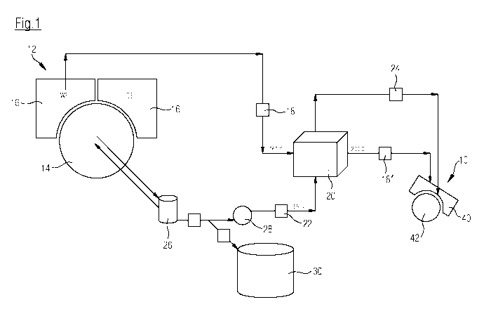
Fig. 1 shows a schematic flow diagram of a first exemplary design form of the
inventive heat recovery system of a machine for the production of a fibrous
web, in
particular a cardboard, paper or tissue web.
The moving fibrous web is hereby acted upon by steam, as well as hot, moist
air in
CA 02752172 2011-08-10
9
the region of a preceding drying zone 10. Subsequently the fibrous web is fed
into a
downstream drying zone 12.
The preceding drying zone 10 may hereby comprise in particular a suction-
equipped
device 42, preferably a suction roll over which the fibrous web is guided,
together
with a least one permeable belt, in particular a structured fabric or TAD-
fabric,
whereby steam or respectively hot, moist air flow first through the permeable
belt
and then through the fibrous web.
The fibrous web can moreover be covered by at least one additional permeable
belt,
especially a press belt, whereby in this case steam or respectively hot, moist
air first
flow through the additional permeable belt or respectively press belt, then
through
the first permeable belt or respectively structured fabric and subsequently
through
the fibrous web. When using a press belt a type of belt press is created
whereby, in
addition to the mechanical pressure, in particular combined hot air and steam
drying
is applied.
In addition, especially a dewatering belt, in particular a felt belt can be
directed over
suction equipped device 42 or respectively the suction roll, together with the
fibrous
web, whereby steam or respectively hot, moist air first flow through the
additional
permeable belt or respectively the press belt, if present, then through the
first
permeable belt or respectively the structured fabric and the fibrous web and
subsequently through the additional dewatering belt.
Downstream drying zone 12 may in particular include a drying cylinder 14,
especially a Yankee-cylinder, as well as a hood 16 allocated to same which can
in
particular be a hot air hood.
CA 02752172 2011-08-10
Hot air 18, especially exhaust air is taken from hood 16 allocated to drying
cylinder
14. To generate at least a portion of the steam for preceding drying zone 10,
condensate and/or fresh water occurring in drying cylinder 14 of the
downstream
drying zone 12 is heated by hot air 18 taken from hood 16 by means of a first
heat
exchanger 20.
To produce at least a portion of the hot, moist air' for preceding drying zone
10, hot
air 18 taken from hood 16 and directed though first heat exchanger 20 is
furnished to
preceding drying zone 10. Since hot air 18 gives off heat to condensate 22 or
respectively to fresh water, their temperature is lowered, so that moist hot
air 18'
eventually furnished to preceding drying zone 10 possesses a temperature
suitable
for the special drying process in this drying zone 10. Hot air 18 furnished to
heat
exchanger 20 can for example have a temperature in the range of 360 C and
moist
hot air 18' eventually furnished to preceding drying zone 10 can have a
temperature
in the range of 200 C. Condensate 22 supplied to heat exchanger 20 can for
example
have a temperature in the range of 165 C.
In the present example steam 24 is produced immediately from the supplied
condensate 22 and/or fresh water by means of the first heat exchanger 20 and
is then
furnished to preceding drying zone 10.
As can be seen in Fig. 1, a steam separator 26 can moreover be provided which
is
located between cylinder 14 and a pump 28, through which condensate 22 is
supplied to heat exchanger 20. In addition a steam generator 30 is also shown
in this
Fig. 1.
CA 02752172 2011-08-10
11
Heat exchanger 20 is an air/water heat exchanger.
Fig. 2 shows a schematic flow diagram of an additional design form of the heat
recovery system which differs from the design form illustrated in Fig. 1
essentially in
that fresh air 34 is heated by the hot air 18 taken from hood 16 by means of a
second
heat exchanger 32 and the thus heated fresh air 34' is furnished as combustion
air to
hood 16 which is allocated to drying cylinder 14 of downstream drying zone 12.
Second heat exchanger 32 therefore is an air/air- heat exchanger.
In the present example, hot air 18 taken from hood 16 is first directed
through second
heat exchanger 32 which is provided for heating fresh air 34 and then through
the
first heat exchanger 20 which is provided for heating condensate 22 and fresh
air,
before it is furnished to preceding drying zone 10.
In principle however, an embodiment is for example also possible where
extracted
hot air 18 is first directed through first heat exchanger 20 which is provided
for
heating condensate 22 and/or fresh water, and then through second heat
exchange 32
which is provided for heating fresh air 34, before it is furnished to
preceding drying
zone 10.
For the remainder, this embodiment is at least fundamentally of the same
design as
shown in Fig. 1, whereby corresponding components are assigned the same
reference
designations.
CA 02752172 2011-08-10
12
Fig. 3 shows a schematic flow diagram of an additional design form of the heat
recovery system which differs from the design form illustrated in Fig. 1
essentially in
that condensate 22 and/or fresh water is heated by first heat exchanger 20
under
increased pressure which, for example is in the range of approximately 3 bar
to
approximately 20 bar and in that condensate 22 and/or fresh water which is
heated
by means of this first heat exchanger 20 and which is under increased pressure
is
then furnished to a flash evaporation device. In this case therefore, steam 24
which
is generated through flash evaporation (flashing) and which, compared to the
furnished heated condensate 22 or respectively fresh water has a lower
pressure is
furnished to preceding drying zone 10.
Heat exchanger 20 can be provided with a preferably flow controlled bypass 38
for
hot air 18 taken from hood 16. This provides greater flexibility in regard to
the
volume of steam produced for preceding drying zone 10, preheating of the
combustion air (compare for example Fig. 4) or even an increase in temperature
in
dryer- or hot air hood 40 allocated to preceding drying zone 10.
As can be seen in Fig. 3, condensate 22' occurring during flashing can be
returned to
first heat exchanger 20 and can be heated in same together with condensate 22
and/fresh water occurring in drying cylinder 14 of downstream drying zone 12
by hot
air 18 taken from hood 16, 12.
For the remainder, this embodiment is at least again fundamentally of the same
design as the embodiment illustrated in Fig. 1, whereby corresponding
components
are assigned the same reference designations.
CA 02752172 2011-08-10
13
Fig. 4 shows a schematic flow diagram of an additional design form of the heat
recovery system which differs from the design form illustrated in Fig. 3
essentially in
that fresh air 34 is heated in addition by means of a second heat exchanger 32
by hot
air 18 taken from hood 16 and the thus heated fresh air 34' is furnished as
combustion air to hood 16 allocated to drying cylinder 14 of downstream drying
zone 12.
In the current example the extracted hot air 18 is first directed through
first heat
exchanger 20 which is provided for heating of condensate 22 and/or fresh
water, and
then through second heat exchanger 32 which is provided for heating fresh air
34,
before it is furnished to the preceding drying zone 10.
Second heat exchanger 32 which is an air/air-heat exchanger can also be
equipped
with a preferably flow regulated bypass 38 for hot air 18 taken from hood 16.
For the remainder, this embodiment is at least again fundamentally of the same
design as the embodiment illustrated in Fig. 3, whereby corresponding
components
are assigned the same reference designations.
Fig. 5 shows a schematic flow diagram of an additional design form of the heat
recovery system which differs from the design form illustrated in Fig. 4
essentially in
that hot air 18 taken from hood 16 is first directed through second heat
exchanger 32
which is provided for heating fresh air 34 and then through first heat
exchanger 20
which is provided for heating condensate 22 and/or fresh water, before it is
furnished
to preceding drying zone 10.
CA 02752172 2011-08-10
14
For the remainder, this embodiment is at least again fundamentally of the same
design as the embodiment illustrated in Fig. 4, whereby corresponding
components
are assigned the same reference designations.
A concrete example is given in the following chart which reproduces the
potential
for steam generation according to the energy content in the exhaust hair of
the hood
or dryer hood 16 allocated to cylinder 14 of downstream drying zone 12. The
produced steam can be utilized at least partially in a steam blow box
allocated to
preceding drying zone 10 or even in the Yankee cylinder. This assumes for
example
a heat recovery system as shown in Fig. 3 where only first heat exchanger 20
is
provided for heat recovery.
The following was assumed for this example:
- Temperature of exhaust air of Yankee-hood: 360 C
- Moisture of exhaust air of Yankee-hood: 450 g water /kg air
- Temperature of exhaust air of Yankee-hood after heat recovery (WR): 250 C
- Yankee-hood exhaust air flow: 6.45 kg/s (dry mass)
- Condensate pressure: 15 bar
- Condensate temperature before heat recovery: 110 C
- Condensate temperature after heat recovery: 183 C
- Pressure of steam produced through flashing: 3 bar.
CA 02752172 2011-08-10
Yankee-hood exhaust air - before --- > Yankee-hood exhaust air - after
WR (heat recovery) WR (heat recovery)
Temperature C 360 Temperature ['Cl 250
Moisture [g/kg] 450 ~ Heat Moisture [g/kg] 450
Enthalpy [kJ/kg] 2080 I recovery Enthalpy [kJ/kg] 1867
Dry air flow k s 6.45 Dry air flow k s 6.45
Total air flow [kg/s] 9.35 ~ (WR) Total air flow [kg/s] 9.35
to belt press hood
Condensate - before WR Condensate - after WR
Temperature loci 110 Temperature loci 183
Pressure bar 15 Pressure bar 15
Enthalpy kJ/k 462 Enthalpy [kJ/kg] 778
Flow [kg/hi 15600 Condensate flow [kg/hi 15600
Flow [kg/s] 4.33 Condensate flow [kg/s] 4.33
Flashing
Steam produced through
flashing
Final pressure bar 3
Enthalpy of saturated steam kJ/kg 2705 Liquid final temperature [ C] 118
Recovered energy kW 1517 Liquid End-enthalpy [kJ/kg] 497
Evaporation-Enthalpy [kJ/kg] 2168
Flash factor % 12.9 %
Produced steam [kg/h] 2020
Produced steam [kg/s] 0.56
The steam production potential in this example is 2020 kg/H of steam at a
pressure
of 3 bar.
CA 02752172 2011-08-10
16
Component identification
preceding drying zone
12 downstream drying zone
14 drying cylinder
16 hood, dryer hood
18 hot air
18' hot air
first heat exchanger
22 condensate
22' condensate
24 steam
26 steam separator
28 pump
steam generator
32 second heat exchanger
34 fresh air
34' fresh air
36 flash evaporation device
38 bypass
hood, dryer hood
42 suction equipped device, suction roll