Note: Descriptions are shown in the official language in which they were submitted.
CA 02752279 2011-09-14
1
Protection device, corresponding method and computer software product
1 FIELD OF THE INVENTION
The present invention pertains to the field of the securing of payment
devices.
The present invention pertains more particularly to a device enabling the
detection of an intrusion into an electronic payment terminal or an opening of
this
terminal aimed at fraudulently obtaining confidential data such as bank data.
There are many devices enabling users to pay for purchases. More
particularly, payment devices using bank cards such as smart chip cards or
smart
magnetic stripe cards have become widespread. These devices are generally
called
payment terminals and enable simple and quick payment for purchases. There are
other devices too using smart chip or magnetic stripe cards: these are for
example
bank terminals such as automated teller machines or automated cash dispensers.
Here below, all these devices, which include both an entry keypad and a memory
card reader are called payment terminals.
Owing to the data handled, payment terminals attract the attentions of
fraudulent individuals. These individuals use every possible means to try and
access the confidential data that are exchanged in the terminals.
One of the ways of accessing these pieces of data consists is to introduce a
bug into the terminal. This bug is used to retrieve data exchanged between the
terminal and the bank card to make a copy of this confidential data with the
aim of
forging false payment cards.
2 PRIOR-ART SOLUTIONS
All payment terminal providers and a certain number of third-party
providers are capable of providing anti-intrusion solutions of varying degrees
of
efficiency.
Indeed, the fraudulent individuals constantly increase their ingenuity when
trying to circumvent such and such a protection measure.
CA 02752279 2011-09-14
2
For obvious reasons of security, the opening of an electronic payment
terminal or the intrusion of a foreign element into an electronic payment
terminal
or again the assembling of a terminal are impermissible operations.
Anti-intrusion measures being proposed include the application of false
keys which are used to detect the opening of the terminal. When the terminal
is
mounted, the keypad of the terminal exerts pressure on the false keys which
are
therefore in permanent contact with the printed circuit. When the keypad is
removed, the false keys are no longer in contact with the printed circuit and
the
security processor activates the requisite protection measures. One of the
problems with these false keys is related to the fact that additional
mechanical
parts need to be provided on the keypad support to detect the dismantling of
the
keypad. These additional mechanical parts are costly.
We may also cite the use of lattices for protecting printed circuits to
prevent the insertion of probes. A probe generally takes the form of an almost
invisible thin metal wire that is inserted into the electronic payment
terminal
through the bank card insertion slot to access the contacts between the bank
card
and the card reader (these contacts are also called "pins").
There are many other existing measures. However, these measures are not
always efficient.
One protective solution that can be envisaged is that of preventing the re-
assembly of a terminal from parts belonging to other terminals. This solution
comes into play when fraudulent individuals try to fabricate or reassemble a
terminal. This is a problem complementary to that of intrusion.
To date, there is no approach by which this problem can be resolved for a
cost deemed to be reasonable. Indeed, it is theoretically possible to provide
the
components of the terminal with identification. To this end, each component
must
be provided with an identifier, for example an RFID, and a security processor
installed in the terminal has to be provided with the list of the identifiers
of the In
addition to being complex this operation also costly since the RFID tags used
to
identify the components considerably increase the cost of the terminal. Now,
it is
CA 02752279 2011-09-14
3
important to provide payment terminals that users can trust and that are not
excessively costly to produce.
3 SUMMARY OF THE INVENTION
The invention does not have the drawbacks of the prior art. Indeed, the
invention pertains to a device for protecting an electronic payment terminal
comprising at least one printed circuit and one casing, the device for
protecting
being characterized in that it comprises:
- at least one capacitive detector comprising two parts, a first part
electrically connected to said printed circuit and a second part mounted
within said casing of said electronic payment terminal without being
electrically connected to said first part, said at least one capacitive
detector
being configured to deliver a reference capacitance when it is mounted in
said electronic payment terminal;
- a capacitive measurement microprocessor electrically connected to said at
least one capacitive detector, configured to detect a variation in
capacitance of said at least one capacitive detector;
- means for transmitting a piece of information representing said variation
of
capacitance when an absolute value of a difference between said measured
capacitance and said reference capacitance exceeds a predetermined
threshold.
Thus, the invention makes it possible to sense an attempted intrusion or
dismantling of the electronic payment terminal. Indeed, any such attempt
against a
portion of the terminal protected by the device of the invention prompts a
variation in the measured capacitance beyond a predefined value and leads to
the
transmission of information on this variation to the security microprocessor
of the
terminal which takes the necessary measures (for example the erasure of the
secured memory).
This invention thus improves the security of the electronic payment
terminal and more particularly participates in an active securing of the
terminal.
CA 02752279 2011-09-14
4
According to one particular embodiment, said device for protecting further
comprises calibration means delivering said reference capacitance.
According to one particular embodiment, said capacitive detector further
comprises a third part consisting of at least one polyhedral element lined
with a
conductive surface.
According to one particular characteristic, said at least one third part is
positioned on said casing of said terminal.
According to one particular characteristic, said at least one third part
defines a unique capacitance associated with said casing of said terminal.
According to another aspect, the invention also pertains to a method for
protecting an electronic payment terminal comprising at least one printed
circuit
and one casing, said device for protecting comprising:
- at least one capacitive detector comprising two parts, a first part
electrically connected to said printed circuit and a second part mounted
within said casing of said electronic payment terminal without being
electrically connected to said first part, said at least one capacitive
detector
being configured to deliver a reference capacitance when it is mounted in
said electronic payment terminal;
a capacitive measurement microprocessor electrically connected to said at
least one capacitive detector, configured to detect a variation in
capacitance of said at least one capacitive detector;
- means for transmitting a piece of information representing said variation
of
capacitance when an absolute value of a difference between said measured
capacitance and said reference capacitance exceeds a predetermined
threshold.
According to the invention, said method for protecting comprises at least one
iteration of the following steps:
- measuring a current value of capacitance by means of said capacitive
detector;
- computing said absolute value of a difference between said measured
CA 02752279 2011-09-14
capacitance and said reference capacitance;
- transmitting said piece of information representing said variation of
capacitance when said absolute value exceeds said predetermined
threshold
5 According to the invention, said method for protecting comprises, during
a
first powering on of said electronic payment terminal, a step for calibrating
said
terminal delivering said reference capacitance.
The invention thus improves the security of the electronic payment
terminal and more particularly takes part in an active securing of the
terminal.
According to another aspect, the invention pertains to a computer software
product downloadable from a communications network and/or stored on a
computer-readable carrier and/or executable by a microprocessor. According to
the invention, such a computer software program comprises program code
instructions to execute the protection method as described here above when it
is
executed on a microprocessor.
4 LIST OF FIGURES
Other features and advantages of the invention shall appear more clearly
from the following description of a preferred embodiment, given by way of a
simple illustratory and non-exhaustive example and from the appended drawings,
of which:
- Figure 1 is a drawing of a detection device according to the invention
applied to a false key;
- Figures 2 and 3 illustrate an embodiment of the invention in which the
detection device comprises a two-part capacitive detector;
- Figure 4 illustrates an embodiment of the invention in which the
detection
device comprises a three-part capacitive detector;
- Figure 5 is a schematic view of a payment terminal according to the
invention.
5 DETAILED DESCRIPTION OF THE INVENTION
CA 02752279 2011-09-14
6
5.1 Description of an embodiment
The principle of the invention consists in providing the electronic payment
terminal with an ability to monitor its internal capacitive environment and
implement security measures based on the measurement of capacitances.
Implementing such measures is simpler than implementing a multiplicity
of protection devices and methods, generally based both on a mechanical
component and on an electronic component. On the contrary, the measurement of
capacitance by the electronic payment terminal, at the units to be protected,
is
simple and requires only the installation of a conductive element such as for
example an electrical wire or a conductive paint.
In one embodiment, the invention also enables the implementing of a
hardware identification of the terminal that is simple and costs little. The
invention also makes it possible to manage anti-intrusion devices simply and
at
low cost. The invention relies on a capacitive measurement made between one or
more capacitive detectors which are formed by at least two parts. Thus, unlike
in
classic capacitive detectors enabling a detection of a variation in
capacitance, for
example when an object is brought close to a detector, the invention proposes
capacitive detectors made up of several parts.
The invention thus proposes the detecting of a modification of the
capacitance (i.e. a modification of the electrical charge) of the detector
when one
of the parts of the detector is shifted or modified relatively to the other
part of the
detector.
To this end, the device according to the invention comprises at least one
capacitive detector comprising two parts, a first part electrically connected
to said
printed circuit and a second part mounted within said casing, said at least
one
capacitive detector being configured to deliver a reference capacitance. This
capacitive detector includes a preliminarily determined capacitance known to a
capacitive measurement microprocessor, electrically connected to the
capacitive
measurement support and configured to detect a variation in capacitance of the
capacitive measurement support. The device also comprises means for
CA 02752279 2011-09-14
7
transmitting a piece of information representing variation in capacitance when
an
absolute value of a difference between a measured capacitance at a given
instant
and the reference capacitance exceeds an also predetermined threshold.
Here below, we present embodiments of the principle of the invention.
These embodiments can of course be combined within one and the same terminal
in order that several security measures may be available.
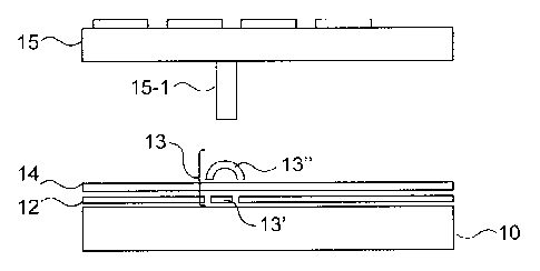
5.2 False keys
As mentioned preliminarily, the joining on of false keys enables detection
of the dismantling of the keypad. The false keys are used to set up a
permanent
connection, by pressure, between the keypad and the printed circuit. Usually,
the
false keys set up an electrical connection that is monitored to detect
opening. This
system is relatively complex to implement. On the contrary, implementing false
keys by means of a two-part capacitive detector does not require any complex
implementation as already described with reference to figure 1.
A false key according to the invention takes the form of a metal "convex
spring-operated dome" 13", constituting a second part of the two-part
capacitive
detector 13. This dome 13" is mounted on the printed circuit 10 which is
positioned in the terminal. A ground plane 12 is drawn on the printed circuit
10.
The first part 13' of the "capacitive detector" 13 is positioned beneath the
dome
13", between the conductive parts of the ground plane. The first part 13' of
the
"capacitive detector" 13 is not electrically connected to the ground plane but
electrically connected to the capacitive microprocessor (not shown). The first
part
13' of the "capacitive detector" 13 and the ground plane 12 are buried beneath
a
layer 14 of prepreg + FR-4 varnish alone well known to those skilled in the
art.
The keypad15 for its part is provided with a push button 15-1. During
assembly, this push button 15-1 crushes the dome 13". The reference
capacitance
is then recorded during the first powering on of the electronic payment
terminal.
This reference capacitance corresponds to that of the terminal when it is
assembled.
CA 02752279 2011-09-14
=
8
If the keyboard of the terminal is dismantled, the dome 13' resumes its
initial shape leading to a modification of the capacitance and therefore a
detection
of the opening. Thus, according to the invention, it is not necessary to
provide for
an electrical connection of the dome 13' with the printed circuit 10, and this
greatly simplifies the implementation.
5.3 Division of the "capacitive detector" into two parts
Referring to figures 2 and 3, a description is provided of an embodiment of
the invention in which the "capacitive detector" is formed by two parts.
In this embodiment of the invention, a first part 13' of the "capacitive
detector" 13 is directly integrated into the printed circuit 10 as a track of
this
printed circuit. In one alternative embodiment (figure 3), the first part of
the
capacitive detector 13 is shifted to a support 13-1, which is itself bonded to
the
integrated electronic circuit 10 to which the first part 13' of the capacitive
detector
13 is electrically connected (13-2).
A conductive surface, which constitutes the second part 13" of the
capacitive detector 13 is positioned on the casing 16 of the terminal. When
the
terminal is closed, this second part 13÷ is positioned against the first part
13' of
the "capacitive detector" 13.
The first part 13' and the second part 13" of the capacitive detector 13 can
be coated with an insulator material or directly poured into the plastic, and
do not
need to be in direct contact, i.e. it is not necessary that the first part 13'
and
second part 13", which are conductive parts, of the "capacitive detector" 13
should be in contact. It is also possible to consider leaving a space between
the
two.
Should the terminal be open, the value of the capacitance measured by the
"capacitive detector" 13 is greatly modified relatively to the reference
value, and
the opening of the terminal is detected. The appropriate security measures are
then
implemented (erasure of the memory of the terminal or only erasure of the
secured memory).
9
The parts of the "capacitive detector" consist of a conductive surface. A
single wire is enough to make these connected surfaces.
5.4 Anti-intrusion in a volume with single identification scheme
In this embodiment of the invention presented with reference to figure 4,
aimed firstly at preventing the opening of the electronic payment terminal and
secondly at making any attempt at snooping by conventional snooping means very
improbable, the capacitive detector 13 is also formed by several parts (13',
13"
and 13").
As in the previous embodiment, the first part 13' of the "capacitive
detector" 13 is directly integrated into the printed circuit 10 as a track of
this
printed circuit (or shifted to a support) as indicated in figures 2 and 3.
The base of the casing 16 is lined with a conductive paint (or surface)
connected to ground. This conductive surface which extends to the bottom of
the
casing is the second part of the capacitive detector. The fact that this
second part
13" of the "capacitive detector" is connected to ground offers major
advantages.
Through the Faraday cage effect, the volume defined by the conductive
paint or conductive surface is insulated from external electromagnetic
disturbances. Moreover, the variations in measurements of capacitance of the
capacitive detector are easy to identify.
This system also greatly reduces the possibilities of electromagnetic
snooping on confidential data (PIN, etc). The volume under surveillance is
therefore clearly demarcated and determined by the ground planes.
Polyhedral elements with conductive surfaces are also laid out in the
casing. These polyhedral elements are the third part 13" ' of the capacitive
detector 13. These polyhedral elements (13"-1 to 13"-4) can be an integral
part
of the casing or permanently bonded to it. These polyhedral elements are used
to
identify the casing so as to connect a casing to a single printed circuit.
This
technique is called "identification by volume pattern".
CA 2752279 2017-08-14
CA 02752279 2011-09-14
Thus, in addition to their anti-intrusive function, the third part of the
capacitive detector 13" fulfils a function of identifying the casing and
provides
an additional level of security.
Indeed, the fact of modifying these polyhedral elements (for example their
5 shape) or their locations significantly modifies the field lines and
therefore the
value of the capacitance measured by the capacitive processor. Thus, if an
attempt
is made to reassemble a terminal from several components of other terminals,
and
especially from a new casing, the reassembled terminal will not be correctly
identified.
10 To reassemble a complete terminal, an attacker cannot re-utilize any new
casing whatsoever; it would be necessary for him to use exactly the same
combination of polyhedral elements and, for this purpose, he must know this
combination. It is easy for the terminal manufacturer to vary the shape,
thickness,
location so as to obtain a large number of possible combinations and therefore
almost nullify the probability that the attacker might recreate the initial
capacitive
environment of the electronic payment terminal. Thus, even if the attacker
successfully reassembles a terminal, it will be unusable.
However, these polyhedral elements are not indispensible to the anti-
intrusion function as such. The additional polyhedral elements are used to
make
the terminal unique at a marginal cost as compared with the cost of joining on
of
RFID tag chips.
An opening or an intrusion by a very small object that is partly conductive
(or even by a dielectric component under certain conditions) is detected and
identified as a "attack" leading to the terminal being placed "attack" mode
(and
leading to an erasure of the confidential data that it contains).
The capacitive detector may consist of a single conductive track, a single
wire being enough. It may also be lined with a plastic film or cast in the
plastic
support of the shell of the terminal.
The last-named technique can apply to the complete terminal or to specific
volumes of the terminal.
CA 02752279 2011-09-14
11
Another advantage of this technique based on a three-part capacitive
detector is that it very sharply limits electromagnetic emissions from the
electronic system of the electronic payment terminal making any snooping on
confidential data very improbable and also overcomes electromagnetic
environmental disturbances through a ground plane system (using the Faraday
cage principle).
Furthermore, this system, in parallel with the environmental compensation
system (see here below), provides efficient protection against untimely and
unsuitable detection of "attacks" due to changes occurring in the surroundings
(for
example the reception of a call by a cell phone placed beside the terminal
etc)
causing the loss of secret keys of the terminal. Indeed, these losses of keys
entail a
major maintenance costs which must be avoided, especially when the payment
terminal is the only terminal installed in a sales point.
5.5 Initial parametrizing
To make it possible to provide the expected service, the device of the
invention must be parameterized in order to determine the predetermined value
of
the reference capacitance. As already explained, this reference capacitance
makes
it possible to control the variation of capacitance over time and determine
whether
this variation exceeds a predetermined value.
When the electronic payment terminal within which the device of the
invention is mounted is first powered on, a measurement of calibration and a
parameterization are performed in order to identify the reference value at
rest in a
neutral electromagnetic environment of the capacitance of the capacitive
detector.
Subsequently, this initial calibration sets up the reference capacitance. In
standard operating mode, a variation of the capacitance measured relatively to
the
reference capacitance is of course accepted, to enable normal working of the
electronic payment terminal.
A value known as "delta" sets the upper and lower bounds within which
the measured capacitances will be considered to be valid. The measurements are
CA 02752279 2011-09-14
12
made periodically, either at regular intervals or at predefined times (at
night for
example).
In the event of a cut in the mains electrical power supply, the security units
of the terminal continue to work on battery. In this case, a system for
periodically
putting the capacitive processor to sleep or reviving it enables regular
measurement of the capacitive detectors (for example every 500 milliseconds).
Indeed, since the device of the invention consumes very little electrical
current, it can be implemented without any mains electrical power supply.
Thus,
the system of the invention can provide for the security of the terminal
continuously with or without the presence of mains current.
Under certain conditions, a system of compensation for ambient conditions
can modify the reference value or base line. Such a system can be joined on to
the
device of the invention to provide for efficient operation of the electronic
payment
terminal as a function of the surroundings in which it is installed.
A software filtering is also performed to highlight events modifying field
lines that are not true operations of installing fraudulent devices (handling
of the
terminal etc).
All these measurements are driven by means of a micro-program
associated with the capacitive measurement microprocessor.
Referring to figure 5, we present an embodiment of a payment terminal
according to the invention.
Such a terminal comprises a memory 51 constituted by a buffer memory, a
processing unit 52, equipped for example with a microprocessor P, and driven
by
the computer program 53 implementing the protection method according to the
invention.
At initialization, the instructions of the computer program code 53 are for
example loaded into a RAM and then executed by the processor of the processing
unit 52. The processing unit 52 inputs at least one piece of information I
such as
identifiers of localization areas. The microprocessor of the processing unit
52
implements the steps of the protection method described here above according
to
CA 02752279 2011-09-14
13
the instructions of the computer program 53 to deliver a piece of processed
information T such as the detection of an attack leading to the elimination of
the
protected data. To this end, the terminal comprises, in addition to the buffer
memory 51:
- at least one capacitive detector comprising two parts, a first part
electrically connected to said printed circuit and a second part mounted
within said casing of said electronic payment terminal without being
electrically connected to said first part, said at least one capacitive
detector
being configured to deliver a reference capacitance when it is mounted in
said electronic payment terminal;
a capacitive measurement microprocessor electrically connected to said at
least one capacitive detector, configured to detect a variation in
capacitance of said at least one capacitive detector;
means for transmitting a piece of information representing said variation of
capacitance when an absolute value of a difference between said measured
capacitance and said reference capacitance exceeds a predetermined
threshold.
These means are driven by the microprocessor of the processing unit.