Note: Descriptions are shown in the official language in which they were submitted.
CA 02752455 2011-09-15
Mobile Monitoring Devices and Methods for Vehicles
The present invention relates to a mobile monitoring device for monitoring
vehicles. The
invention additionally relates to a method for such monitoring.
In the case of vehicle monitoring speed measurement values are often combined
with
recorded images of a vehicle so that this can be clearly identified for
enforcement of traffic
violations. If such monitoring operations are conducted from a mobile moving
monitoring
platform, this currently requires complex manual matching of the speed
measurement values
to the recorded images and vice versa, since the detection ranges of usual
speed measurement
sensors and image recording cameras never overlap precisely. Because of this
and in view of
the constantly changing relative speeds in flowing traffic, ambiguities can
result between
different recorded images and speed measurement values that make an absolute
match
impossible.
The set aim of the invention is to provide mobile monitoring devices and
methods, which
substantially enable vehicles to be monitored in an automated manner in
flowing traffic, i.e.
both with moving monitoring platforms and moving vehicles to be monitored.
This aim is achieved in a first aspect of the invention with a mobile
monitoring device with
a sensor for measuring the speed of vehicles passing through a first detection
range, said
sensor providing the speed measurement value of a passage of a vehicle with a
time stamp;
a sensor for at least indirectly measuring the geometry, preferably measuring
the length, of
vehicles passing through a second detection range, said sensor providing the
geometry
measurement value of a passage of a vehicle with a time stamp;
a camera for recording images of vehicles passing through a third detection
range, said
camera providing the image of each passage of a vehicle with a time stamp; and
an evaluation device connected to the camera and the said sensors, which is
configured for
calculating from the speed measurement value, its time stamp and the first
detection range
and also from the geometry measurement value, its time stamp and the second
detection
range, the place and time at which a passage of a vehicle is to be expected in
the third
detection range in order to determine the matching image on the basis of its
time stamp and
third detection range therefrom.
CA 02752455 2011-09-15
2
In a second aspect the invention achieves its aims with a method for
monitoring vehicles,
with the following steps in any desired sequence:
measuring the speed of a vehicle passing through a first detection range and
providing the
speed measurement value with a time stamp;
at least indirectly measuring the geometry, preferably the length, of a
vehicle passing through
a second detection range and providing the geometry measurement value with a
time stamp;
recording images of vehicles passing through a third detection range and
providing each
image with a time stamp;
additionally with the subsequent steps:
calculating from the speed measurement value, its time stamp and the first
detection range
and also from the geometry measurement value, its time stamp and the second
detection
range, the place and time at which a passage of a vehicle is to be expected in
the third
detection range, and
determining the matching image on the basis of its time stamp and third
detection range
therefrom.
The invention takes into account the different detection ranges, which the
individual sensors
and cameras of a mobile monitoring device have, and calculates expected values
for the
movements of the monitored vehicle within the detection ranges, so that
vehicle images
recorded in one detection range can be automatically linked with speed
measurement values
originating from a different detection range therefrom.
The term "detection range" used here covers every segment of surrounding area
that can be
covered by means of sensors or cameras from the current location of the mobile
monitoring
device, whether this is a conical, pyramid-shaped, prismatic, linear, plane
etc. segment of
area or the like.
The calculation can also be conducted as post-processing, i.e. the detection
ranges or time
stamps can also be assigned after all individual measurements have been
conducted and
stored.
The use of further sensors, the sensor data of which are matched to the
respective passing
vehicle by the described method, is also conceivable in principle: exhaust gas
sensors, sound
CA 02752455 2011-09-15
3
volume sensors, temperature sensors for tyre or brake inspection, video
sensors for tyre
inspection, hazardous transport load markings, badges, stickers etc.
All images mentioned here can also each be a component of a video sequence.
A particularly preferred embodiment of the invention that serves to monitor
vehicles
equipped with DSRC OBUs (dedicated short-range communication onboard units),
such as
those used as part of DSRC road toll systems, for example, is distinguished by
a DSRC
transceiver for DSRC communication with DSRC OBUs of vehicles passing through
a fourth
detection range, said DSRC transceiver providing the DSRC communication of
each passage
of a vehicle with a time stamp, wherein the evaluation device is additionally
configured to
determine the matching DSRC communication to the determined image on the basis
of its
time stamp and fourth detection range.
The corresponding preferred embodiment of the method according to the
invention is
distinguished by the additional steps of conducting DSRC communications with
the DSRC
OBUs of vehicles passing through a fourth detection range and providing each
DSRC
communication with a time stamp; and determining the matching DSRC
communication to
the determined image on the basis of its time stamp and fourth detection
range.
DSRC OBUs are used in DSRC road toll systems to conduct DSRC communications
with
roadside radio beacons (roadside equipment, RSE). The DSRC communications
ultimately
end in toll transactions in the road toll system. Mobile monitoring platforms
are also used for
monitoring vehicles with DSRC OBUs and these interrogate the DSRC OBUs of the
vehicles
in flowing traffic to retrieve data therefrom for monitoring of the toll
transactions generated
in the road toll system, or simply to check the presence of a operable DSRC
OBU in a
vehicle. This type of monitoring poses the additional problem that the
transmit-receive ranges
of the DSRC transceiver of the mobile monitoring device and the DSRC OBU of
the
monitored vehicle in its overlap range necessary for the radio communication
form a
detection range that can differ greatly from the detection ranges of the other
sensors and
cameras of the mobile monitoring device. This now results in a problem of
matching between
the DSRC radio communications, on the one hand, and the images recorded for
enforcement
purposes, on the other. The invention solves this problem by calculating
expected values for
the time and place when or where a vehicle, with which a DSRC communication
has been
CA 02752455 2011-09-15
4
conducted, is in the detection range of the camera to enable a clear match of
an image to a
DSRC communication.
It is understood that in this embodiment the determination of the speed
measurement value is
possibly only an interim result on the way to matching the DSRC communications
to the
images, i.e. does not represent an output signal or result of the monitoring
device or
monitoring method itself, but merely serves to calculate the said expected
values and thus
match the DSRC communications to the images.
The speed of the vehicles can in fact be measured on any manner known in the
art. According
to a first preferred embodiment of the invention that is intended for the DSRC
systems, the
speed is measured using the DSRC transceiver of the mobile monitoring device
itself, that is
preferably by Doppler measurement of the DSRC communications, i.e. evaluation
of the
relative speed-based Doppler effect that occurs in the radio communication.
Accordingly, in
this embodiment the first and the fourth detections areas are the same,
because the speed
measurement sensor is formed by the DSRC transceiver itself. Installation of a
separate speed
measurement sensor becomes unnecessary as .a result of this embodiment.
In an alternative preferred embodiment also suitable for vehicles that are not
equipped with
DSRC OBUs, the speed is measured with a laser scanner from the mobile
monitoring device,
or by evaluating two consecutive images of a camera.
A geometry, e.g. the number of axles, length or height of a passing vehicle,
can preferably
also be detected with such a laser scanner. For example, the laser scanner can
transmit a
scanning beam onto the vehicle in a plane located normal to or on an angle to
the direction of
travel. From a number of axles or vehicle height detected in such a manner,
for example, an
associated geometry, e.g. the length, of the vehicle can be determined on the
basis of a table
of number of axles or vehicle heights and vehicle geometries typically
associated therewith.
Alternatively, the geometry measurement sensor can be formed by the DSRC
transceiver,
which receives vehicle data from the DSRC OBU as part of a DSRC communication,
from
which data it calculates a geometry, preferably the length, of the vehicle, in
which case the
second and the fourth detection range are the same. Moreover, the data of the
geometry
sensor can also be used for further plausibility checks such as determination
of a vehicle
CA 02752455 2011-09-15
volume, a vehicle class etc., against which the recorded images, speed
measurement values
and/or DSRC communications can be counterchecked for plausibility of the
match.
Further features and advantages of the invention will be seen from the
following description
5 of a preferred exemplary embodiment with reference to the accompanying
drawings:
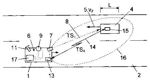
Figures 1 to 3 show a mobile monitoring device mounted on a monitoring vehicle
for
monitoring vehicles in flowing traffic in three different positions of use,
which at the same
time illustrate three phases of the method of the invention.
With reference to Figures 1 to 3, a monitoring vehicle 1 is respectively shown
therein that is
moving on a lane of a road 2 in a direction of travel 3 at a speed v1. The
monitoring vehicle 1
serves to monitor other vehicles 4 in flowing traffic on the road 2, which in
the example
shown here are moving in an opposite lane of the road 2 in an opposite
direction of travel 5 at
a speed v2 and are travelling in oncoming traffic past the monitoring vehicle
1. However, it is
understood that the monitoring vehicle 1 can also monitor vehicles 4
travelling in the same
direction, or that one or both vehicles 1, 4 can be temporarily at a
standstill in stop and go
traffic. The different directions of travel 3, 5 and speeds, VI, v2 of the
monitoring vehicle 1
and the monitored vehicle 4 create time-variable conditions that render a firm
geometric
match between the monitoring vehicle I and the vehicle 4 impossible.
For monitoring the vehicle 4 the monitoring vehicle I carries a mobile
monitoring device 6,
which comprises the following components, some of which may also coincide:
a first sensor 7 for measuring the relative speed yr = v2 - VI of the vehicle
4 in relation to the
monitoring vehicle 1 when said vehicle 4 is located in the detection range 8
of the sensor 7 or
is passing therethrough;
a second sensor 9, which at least indirectly measures the geometry, here the
length L, of the
vehicle 4 when this is located in the detection range 10 of the sensor 9;
at least one camera 11 for recording an image B of the vehicle 4 when this is
located in the
detection range 12 of the camera 11 or is passing therethrough;
an (optional) DSRC transceiver 13, which can conduct a radio communication 14
with an
(optional) DSRC OBU 15 of the vehicle 4, when this is located in the detection
range 16 of
the DSRC transceiver 13 or is passing therethrough;
CA 02752455 2011-09-15
6
the detection range 16 is the intersection from the transceiver range of the
DSRC transceiver
13 and the transceiver range of the DSRC OBU 15; and
an evaluation device 17 connected to the above components.
During operation the sensor 7 measures the (relative) speed yr of the passing
vehicles 4 and
provides each speed measurement value yr with a respective time stamp TS1 of
the time at
which it was detected. With knowledge of the inherent speed v1 of the vehicle
1, conclusions
can be made from the relative speed yr as to the inherent speed v2 of the
vehicle 4.
In the same way, the sensor 9 measures at least one geometry of the passing
vehicles 4, here
the length L, and provides each geometry measurement value L with a time stamp
TS2 of the
time at which it was detected. The camera 11 photographs the vehicles 4
passing through its
detection range 12 and provides each recorded image 11 with a time stamp TS3
of the time at
which it was detected. Optionally, the DSRC transceiver 13 conducts DSRC
communications
14 with the DSRC OBU 15 of the passing vehicles 4 and stores each conducted
DSRC
communication 15 with a time stamp TS4 of when it was conducted.
The evaluation device 17 links the speed measurement values, geometry
measurement values,
camera images and DSRC communications received from the sensors 5, 9, the
camera 11 and
the optional DSRC receiver 13 taking their respective time stamps TSI-TS4 and
detection
ranges 8, 10, 12, 16 into account, so that they can be matched to one another.
Since the
respective detection ranges 8, 10, 12 and 16 are known in relation to the
coordinate system of
the monitoring device 6, e.g. defined by spatial angle, planes, sectors etc.,
from the speed
measurement values, geometry measurement values, camera images and/or DSRC
communications occurring at the respective times 151, 152, 153, 154 expected
values can be
calculated for the place and the time, in or at which a passage of a vehicle
attributable to the
vehicle 4 occurs in the detection range 12 of the camera 11, so that the
images B recorded by
the camera 11 in the detection range 12 with their time stamps TS3 can be
compared
therewith. Thus, the respective matching image B to each speed measurement
value yr can be
determined and vice versa, even when the detection ranges 8, 12 of the speed
sensors 7 and
the camera 11 do not overlap. The vehicle geometry, in particular the number
of axles A
and/or the vehicle length L, is also evaluated therewith to exclude
ambiguities, e.g. to validate
a vehicle 4 recorded in an image B on the basis of its length detected in the
image compared
CA 02752455 2011-09-15
7
to the length L measured by the sensor 9, or to distinguish between several
vehicles 4, which
were recorded in the very same image B because of dense traffic.
In an embodiment, the speed measurement value yr or v2 of the vehicle 4
determined in this
manner can also be used only as an interim result on the way to matching a
DSRC
communication 14 to a recorded image B. Thus, with knowledge of the detection
range 16 of
the DSRC transceiver 13, the aforementioned speed and geometry measurement
values of the
sensors 7, 9, the detection ranges 8. 10 and the time stamps TSI-TS4, a DSRC
communication
with a vehicle 4 can also be matched to the respective image B of the vehicle
4. For this, the
measured or calculated speed vector v2 of the vehicle 4 and the known speed
vector yr of the
monitoring vehicle 1 are evaluated, for example, in association with the
respective time
stamps TS I -TS4 and detection ranges 8, 10, 11, 12, 16 in order to estimate
or extrapolate the
place and time in or at which the vehicle 4, with which a DSRC communication
14 took
place, should appear in the detection range 12 of the camera 11 in order to
match the image B
of the camera 11, wherein the time stamp TS3 and the position of the vehicle 4
recorded in
the image B matches these detection values.
Any sensors known in the art can be used for the speed measurement sensor 7
and the
geometry measurement sensor 9. In a first embodiment a laser scanner is used
for the
geometry measurement sensor 9 that, for example, transmits a scanning beam in
a plane
located normal to or on an angle to the direction of travel, i.e. its
detection range 10 is a
plane, and the vehicle 4 is scanned by the motion of the monitoring vehicle 1
and/or vehicle 4
in order to generate a 3D image of the vehicle 4.
The vehicle length L is frequently represented in a distorted manner in such a
3D image of
the vehicle 4 because of the vehicle speed v2. In this case, the vehicle
length L can be
determined indirectly therefrom: thus, from a correctly detected vehicle
height (or the vehicle
volume), for example, a conclusion can be drawn as to a specific class of
vehicle such as
automobile, lorry, lorry with trailer etc., for which specific typical vehicle
lengths L can be
determined. For this, the sensor 9 can contain e.g. a table of typical vehicle
heights and
associated typical vehicle lengths and can thus determine an appropriate - if
only approximate
- length L of the vehicle 4 on the basis of the measured vehicle height.
CA 02752455 2011-09-15
8
Alternatively, the sensor 9 could be a 3D laser scanner, for example, which
very quickly
provides a 3D image of a matching vehicle 4 - quasi photographically - in one
action, from
which a geometry, such as the vehicle length L, can be directly determined.
One more alternative would be, for example, that the sensor 9 determines the
number of axles
A of the vehicle 4, e.g. by laser scanning or LIDAR or radar Doppler
measurement of the
rotating wheels of the vehicle 4. The sensor 9 can then again contain a table
of vehicle
lengths L or dimensions typical for specific numbers of axles A, for example,
and thus
determine an associated - if only approximate - geometry such as the length L
of the vehicle
4.
The speed measurement sensor 7 can also be formed by a laser scanner, e.g. in
the manner of
a LIDAR speed measurement gun. Alternatively, the speed of the vehicle 4 could
also be
measured with a 2D or 3D laser scanner, e.g. by means of two measurements in
quick
succession and determination of the local displacement of the vehicle 4
between the two
measurements. Therefore, one and the same laser scanner can optionally be used
for both the
speed measurement sensor 7 and for the geometry measurement sensor 9.
In an alternative embodiment, the speed can also be measured with the aid of
the optional
DSRC transceiver 13. For this, Doppler measurements can be conducted on the
DSRC
communications 14, for example, to determine the relative speed vr.
Alternatively the speed
can be measured using a transceiver 13 with infrared transmission during the
course of the
vehicle communication.
It would also be conceivable that the DSRC OBU 15 measures its speed itself
and sends this
to the DSRC transceiver 13 as part of a DSRC communication 14, which is also
covered in
the definition here that the DSRC transceiver 13 forms a speed measurement
sensor.
If the speed is measured with the DSRC transceiver 13, it is understood that
the first and the
fourth detection range 8 and 16 coincide.
The DSRC transceiver 13 can, moreover, also form the geometry measurement
sensor 9 if as
part of a DSRC radio communication 14 it receives vehicle data from the DSRC
OBU 15,
from which it can calculate a geometry of the vehicle 4, e.g. the length L.
For example, the
CA 02752455 2011-09-15
9
DSRC OBU 15 transmits information concerning the vehicle class or number of
axles of the
vehicle 4, from which - again by way of a table of typical vehicle geometries
for typical
vehicle classes or numbers of axles - the associated vehicle geometry can be
calculated. If the
geometry measurement sensor 9 and the DSRC transceiver 13 coincide, it is
understood that
the detection ranges 10, 16 also coincide accordingly.
Alternatively, the transceiver 13 can also be configured for a short-range
transmission
technology other than DSRC, e.g. infrared or any desired microwave technology.
Consequently, the invention is not limited to the represented embodiments, but
covers all
variants and modifications that come within the framework of the attached
claims.