Note: Descriptions are shown in the official language in which they were submitted.
CA 02753379 2011-08-23
WO 2010/108279
PCT/CA2010/000460
1
Adjustable side dam for continuous casting apparatus
TECHNICAL FIELD
This invention relates to the casting of metal strip articles by means of
continuous strip casting apparatus of the kind that employ continuously moving
elongated casting surfaces and side dams that confine the molten and semi-
solid
metal to the casting cavity formed between the moving casting surfaces. More
particularly, the invention relates to the side dams themselves, and
particularly, but
not exclusively, to those intended for the casting of aluminum and alloys
thereof.
BACKGROUND ART
Metal strip articles (such as metal strip, slab and plate), particularly those
made of aluminum and aluminum alloys, are commonly produced in continuous
strip
casting apparatus. In such apparatus, molten metal is introduced between two
closely spaced (usually actively cooled) elongated moving casting surfaces
forming a
casting cavity, and is confined within the casting cavity until the metal
solidifies (at
least sufficiently to form an outer solid shell). The solidified strip
article, which may
be produced in indefinite length, is continuously ejected from the casting
cavity by
the moving casting surfaces. One form of such apparatus is a twin-belt caster
in
which two confronting belts are rotated continuously and molten metal is
introduced
by a launder or injector into a thin casting cavity or mold formed between the
confronting regions of the belts. An alternative is a rotating block caster in
which the
casting surfaces are formed by blocks that move around fixed paths and align
with
eachother within the casting cavity. In both kinds of apparatus, the molten
metal is
introduced at one end of the apparatus, conveyed by the moving belts or blocks
for a
distance effective to solidify the metal, and then the solidified strip
emerges from
between the belts or blocks at the opposite end of the apparatus.
In order to confine the molten and semi-solid metal within the casting cavity,
i.e. to prevent the metal escaping laterally from between the casting
surfaces, it is
usual to provide metal dams at each side of the apparatus. For twin-belt and
rotating
block casters, side dams of this kind can be formed by a series of metal
blocks joined
CA 02753379 2011-08-23
WO 2010/108279
PCT/CA2010/000460
2
together to form a continuous line or chain extending in the casting direction
at each
side of the casting cavity. These blocks, normally referred to as side dam
blocks, are
trapped between and move along with the casting surfaces and are recirculated
so
that blocks emerging from the casting cavity exit move around a guided circuit
and
are fed back into the entrance of the casting cavity. The blocks are guided
around
this circuit by means of a metal track, or similar guide, on which the blocks
can slide
in a loose fashion that allows for limited movement between the blocks,
especially as
they move around curved parts of the circuit outside the casting cavity.
A problem with side dams made of blocks of this kind is that it is sometimes
desired to change the through-thickness convergence of the belts, i.e. to make
the
casting cavity thinner at its exit than at its entrance (referred to as
convergent) in
order to extract more heat from the metal slab, or alternatively, to make the
casting
cavity thicker at the exit (referred to as divergent) in order to extract less
heat from
the metal slab. A requirement that the belts also drive the side dam blocks
through
the casting cavity may limit the extent to which the casting belts can be
changed in
this way.
The casting belts or blocks extract heat from the molten metal passing
through the casting cavity, but heat is also extracted at the sides of the
cavity where
the molten metal contacts the side dam blocks which are usually made of a heat
conductive material such as cast iron or mild steel. This heat extraction at
the sides
of the cavity often changes the microstructure and thickness of the slab in
those
areas, resulting in undesirable side-to-center non-uniformity of the cast
metal slab.
US patent No. 4,869,310 issued to Yanagi et al. on September 26, 1989
discloses a twin-belt casting apparatus having side dams provided by moving
side
dam blocks as explained above. For comparison with the moving side dam blocks,
however, this patent also shows the use of fixed side dams in Figs. 7 and 8 of
the
patent. These fixed side dams extend for the full length of the casting cavity
and are
said to be liable to cause seizure when the metal solidifies. Also, it is said
that a
change in the width of the cast piece is not possible when such fixed side
dams are
employed.
There is therefore a need to address the problems mentioned above.
CA 02753379 2013-04-09
3
DISCLOSURE OF THE INVENTION
According to one exemplary embodiment, there is provided a side dam for a
continuous metal casting apparatus having elongated opposed casting surfaces
advancing in a casting direction forming a casting cavity therebetween, the
side dam
comprising an upstream end and a downstream end, an elongated generally
straight
upstream part and an elongated generally straight downstream part that are
mutually laterally pivotable at a point between said upstream end and said
downstream end, at least one anchor point attachable to a fixed element of
said
casting apparatus to prevent the side dam from being dragged in said casting
direction by said advancing casting surfaces, and a smooth metal-contacting
side
surface extending continuously from said upstream end to said downstream end
of
the side dam and having regions thereof formed on said upstream part and said
downstream part, whereby mutual lateral pivoting of said upstream part and
said
downstream part of the side dam enables said regions of the smooth metal-
contacting side surface to be moved out of mutual coplanar alignment wherein
the
smooth metal contacting side surface continues to extend continuously from
said
upstream end to said downstream end of the side dam during pivoting and after
said
regions are moved out of mutual coplanar alignment.
The smooth continuous surface is preferably an outer surface of an elongated
strip of flexible refractory material extending continuously from the upstream
end to
the downstream end of the side dam, and the strip is preferably made of a
material
that has a coefficient of friction with molten metal such that the metal does
not build
up on the surface as the metal solidifies during casting. For example, the
elongated
strip may be made of flexible graphite composition. Preferably, the elongated
strip
stands proud (e.g. by a distance of up to about lmm) of the remainder of the
upstream and downstream parts of the side dam at the surfaces thereof that, in
use,
confront the casting surfaces of the continuous casting apparatus. Ideally,
the
remainder of the surfaces of the side dam that, in use, confront the casting
surfaces
CA 02753379 2013-04-09
4
have a coating of a refractory low friction wear-resistant material (e.g. a
metal nitride,
such as boron nitride).
The side dam may have a layer of heat insulating material (e.g. refractory
insulating board) adjacent to the elongated flexible strip. This reduces heat
loss from
the metal being cast into the fabric of the side dam. The side dam may also
have an
elongated backing element made of rigid material (preferably a metal such as
steel)
along a side of the upstream and/or downstream parts opposite to the metal-
contacting side surface of the side dam.
The side dam preferably also has at least one anchor point (which may be a
hold for a bolt, a region for application of adhesive, an attachment bracket,
or the
like) adjacent to the upstream end for rigid attachment of the side dam to an
element
of the continuous metal casting apparatus. This prevents the side dams from
being
dragged in the casting direction by the casting surfaces.
The side dam preferably has a hinge acting between the upstream and
downstream parts thereof, the hinge enabling and guiding the mutual pivoting
of the
parts. The hinge may be a door-type hinge made of the material of the backing
element, or it may simply be a web of flexible material adhered or otherwise
attached to each part of the side dam.
The side dam preferably has a length from the upstream end to the
downstream end that is less than the length of a casting cavity of a
continuous
casting apparatus with which the side dam is used, but greater than the
downstream
extent of molten and semi-solid metal cast in the apparatus. The side dam
therefore
merely covers the distance over which metal may leak or flow from the casting
cavity.
Another exemplary embodiment provides a continuous metal casting
apparatus comprising opposed casting surfaces advancing in a casting direction
forming a casting cavity therebetween, a metal inlet for introducing molten
metal
into said cavity, and two side dams for confining molten metal to said casting
cavity,
wherein at least one of said two side dams has at least one anchor point
attached to
a fixed element of said casting apparatus to prevent said at least one side
dam from
being dragged in a casting direction by said advancing casting surfaces, and
comprises
CA 02753379 2013-04-09
=
4a
an upstream end and a downstream end, an elongated generally straight upstream
part and an elongated generally straight downstream part that are mutually
laterally
pivotable at a point between said upstream end and said downstream end, and a
smooth metal-contacting side surface extending continuously from said upstream
end to said downstream end of the side dam and having regions thereof formed
on
said upstream part and said downstream part, whereby mutual lateral pivoting
of
said upstream part and said downstream part of the side dam enables said
regions of
the smooth metal-contacting side surface to be moved out of mutual coplanar
alignment wherein the smooth metal-contacting side surface continues to extend
continuously from said upstream end to said downstream end of the side dam
during
and after said regions are moved out of mutual coplanar alignment.
In the casting apparatus, the casting surfaces are preferably surfaces of a
pair
of opposed rotating casting belts or, alternatively, surfaces of a series of
rotating
casting blocks. The metal inlet is preferably a molten metal injector having a
nozzle
projecting between the opposed casting surfaces, and wherein at least one of
the
CA 02753379 2011-08-23
WO 2010/108279
PCT/CA2010/000460
side dams is attached to the nozzle, either to the outer surface of the nozzle
or the
inner surface thereof.
In the casting apparatus, the upstream and downstream part of the side dam
is preferably arranged at a convergent angle, or a divergent angle, and most
5 preferably the latter, relative to a casting direction of the metal. This
angle is
preferably 100 or less.
Another exemplary embodiment provides a continuous metal casting
apparatus comprising opposed rotating casting surfaces forming a casting
cavity
therebetween, a metal inlet for introducing molten metal into the cavity, and
two
side dams for confining molten metal to the casting cavity, wherein at least
one of
the two side dams comprises a flexible elongated strip of low friction
refractory
material that is resistant to attack by molten metal, the flexible elongated
strip having
a metal-contacting side and an opposed side, an elongated block of heat
insulating
material contacting the opposed side of the flexible elongated strip, the
elongated
block having a surface remote from the flexible elongated strip, and a backing
element of rigid material contacting the remote surface of the elongated
block,
wherein the flexible elongated strip, the elongated block and the backing
element fit
between the opposed casting surfaces adjacent to the metal inlet thereof in
contact
with both of the opposed casting surfaces.
While the exemplary embodiments are particularly suited for use with, or the
casting of, aluminum or aluminum alloys, it is also possible to cast other
metals in the
same way, e.g. copper, lead and zinc, and even magnesium and steel.
BRIEF DESCRIPTION OF THE DRAWINGS
Exemplary embodiments of the invention are described in detail in the
following with reference to the accompanying drawings, in which:
Fig. 1 is a top plan view of a twin-belt casting apparatus with the top belt
removed to show side dams according to an exemplary embodiment;
Fig. 2 is a simplified side view of a twin belt casting apparatus showing a
side
dam of the kind illustrated in Fig. 1;
CA 02753379 2013-04-09
6
Fig. 3 is a perspective view of a side dam, shown in isolation, according to
an
exemplary embodiment;
Fig. 4 is a vertical transverse cross-section of the side dam of Fig. 3 taken
between an upstream and a downstream end thereof;
Fig. 5 is a top plan view similar to that of Fig. 1, but illustrating an
alternative
arrangement for positioning side dams according to another exemplary
embodiment;
and
Fig. 6 (which appears on the same sheet of drawings as Fig. 4) is a vertical
cross-section of the casting machine shown in Fig. 5 (but with molten metal
omitted)
showing only the region around the tip of the nozzle 18 and an immediately
adjacent
part of the casting cavity.
BEST MODES FOR CARRYING OUT THE INVENTION
The exemplary embodiments of this invention described in the following are
directed in particular for use with twin belt casters, e.g. of the kind
disclosed in US
patent No. 4,061,178 issued to Sivilotti et al. on December 6, 1977. However,
other
exemplary embodiments may be used with casters of other kinds, e.g. rotating
block
casters. Twin belt casters have an upper flexible belt and a lower flexible
belt that
rotate about rollers and/or stationary guides. The belts confront each other
for part
of their length to form a thin casting cavity or mold having an entrance and
an exit.
Molten metal is fed into the entrance and a cast metal slab emerges from the
exit.
Cooling water sprays are directed onto the interior surfaces of the belts in
the region
of the casting cavity for the purpose of cooling the metal. The molten metal
may be
introduced into the casting cavity by means of a launder, but it is more usual
to
provide an injector that projects partially into the casting cavity between
the belts at
the entrance. Exemplary embodiments may be used most preferably with a type of
metal injector having a flexible nozzle as disclosed in US patent No.
5,671,800 issued
to Sulzer et al. on September 30, 1997.
CA 02753379 2011-08-23
WO 2010/108279
PCT/CA2010/000460
7
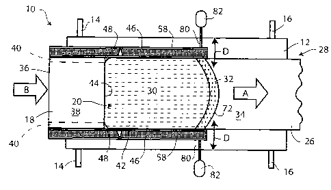
Fig. 1 of the accompanying drawings is a top plan view of a twin belt casting
apparatus 10 with a top belt removed illustrating a casting operation in
progress.
Fig. 2 is a simplified schematic side view of the same apparatus with both
rotating
casting belts 11 and 12 shown in place. The lower belt 12 is visible in Fig. 1
and it
rotates around axes 14 and 16 in the direction of arrow A (the casting
direction).
Similarly, the upper belt (not visible in Fig. 1) rotates in the opposite
sense around
axes 14' and 16'. Molten metal 42 (e.g. an aluminum alloy) is introduced into
the
apparatus at an upstream entrance as represented by arrow B and it passes
through a
molten metal injector 18 into a casting cavity 20 formed between opposing
elongated surfaces 22 and 24 (see Fig. 2) of the upper belt 11 and the lower
belt 12.
The molten metal is conveyed in the direction of arrow A by the rotating belts
and it
eventually solidifies to form a strip article 26 in the form of a cast slab of
indefinite
length that emerges from the apparatus at an exit 28 where the belts 11, 12
change
direction as they circulate around their defined paths. In the case of many
metals
(particularly aluminum alloys), the metal becomes semi-solid while
transforming from
the fully molten to the fully solid state. Consequently, the metal in the
casting cavity
has a molten region 30, a semi-solid region 32 and a fully solid region 34 as
it
proceeds from injector 18 to exit 28. The semi-solid region 32 is somewhat
curved as
shown because heat tends to be extracted more slowly at the center of the cast
slab
than at the sides.
The injector 18 has a metal-conveying channel 36 formed between upper and
lower walls 38, 39 (only the upper wall 38 is visible in Fig. 1, but both are
visible in
Fig.6) held apart by side walls 40 represented by broken lines in Fig. 1. The
molten
metal 42 emerges into the casting cavity between the belts through an end
opening
or nozzle 44 at the downstream end of the injector 18, and the molten metal is
laterally confined between a pair of stationary side dams 46 until it is fully
solid and
self-supporting. Because the side walls 40 of the injector 18 have substantial
lateral
width, the molten metal initially flows laterally (as well as forwardly) to
contact the
side dams 46 as it emerges from nozzle 44 as shown at 48.
One of the side dams 46 is shown in isolation in Fig. 3. The side dam has an
upstream end 47 and a downstream end 49, and a smooth unbroken metal-
CA 02753379 2011-08-23
WO 2010/108279
PCT/CA2010/000460
8
contacting surface 50 that extends continuously between the upstream and
downstream ends of the side dam. The other lateral side of the side dam has an
opposed outer surface 52. The metal-contacting surface 50 is formed by an
outer
surface of a flexible elongated strip 54 made of flexible preferably low
friction
refractory material that is able to resist attack by the molten metal and
resists the
build-up of solidified metal during casting. The material is preferably a
flexible
graphite composition, e.g. a material sold under the trademark Grafoil by
American
Seal and Packing (a division of Steadman & Associates, Inc.) of Orange County,
California, USA. However, other materials that have non-wetting, non-reacting,
low
heat transfer, high wear-resistant and low friction properties may be
employed, e.g.
carbon-carbon composites, refractory board having a coating of boron nitride,
and
solid boron nitride. The strip 54 is backed by an elongated block 56 of heat
insulating
material, e.g. refractory board. This may be the same kind of material from
which the
injector 18 is made, or a different material, e.g. the material available from
Carborundum of Canada Ltd. as product no. 972-H refractory sheet. This is a
felt of
refractory fibers typically comprising about equal proportions of alumina and
silica
and usually containing some form of rigidizer, e.g. colloidal silica, such as
Nalcoag 64029. The elongated block 56 is formed in two parts, i.e. an
upstream part
56A and a downstream part 56B. Thus, the side dam block is also formed in two
parts
except for the strip 54 that extends without break and bridges the junction
between
the two parts 56A and 568 of the underlying block 56. The metal-contacting
surface 50 thus has an upstream region 50A formed on part 56A of the elongated
block 56 and a downstream region 50B formed on part 56B of the elongated
block.
The block 56 is itself backed by a rigid backing element 58 made, for example,
of steel
or other metal, and it too is formed in two parts 58A and 58B joined together
by a
vertical-axis hinge 60. The hinge 60 allows the upstream and downstream parts
of
the block 56 to be mutually pivotable so that the upstream and downstream
regions
of the metal-contacting surface 50 may be moved out of the mutally coplanar
alignment that they have when the side dam is perfectly straight. This
pivoting is
accommodated by oblique surfaces formed at inner ends 61 and 62 of the parts
56A
and 56B of the insulating block 56 which together create a V-shaped opening
64, and
CA 02753379 2011-08-23
WO 2010/108279
PCT/CA2010/000460
9
also by the flexible nature of the strip 54 which allows bending of this
element in the
region of the opening 64. The flexible strip, insulating block and backing
element are
securely attached to each other, e.g. by mechanical fasteners (not shown).
Such
fasteners preferably attach the flexible strip 54 with a certain amount of
longitudinal
play relative to the adjacent insulating block 56 (either in region 56A or
region 56B or
both) so that part 46B of the side dam may be pivoted clockwise (referring to
Fig. 3)
without causing the flexible strip to stretch at the opening 64 (since
pivoting in this
direction cannot be accommodated by flexing alone, as it can be for pivoting
in the
anti-clockwise direction).
The side dams 46 remain stationary in the casting apparatus and the low
friction property of the flexible elongated strip 54 resists any tendency of
the moving
metal to stick or jam against the side dam 46 as it solidifies and is carried
forwards by
the belts. The elongated strip 54 is dimensioned to contact both of the
casting belts
and the flexible nature of the strip allows it to yield to the shape of the
belt and to
form a good seal against molten metal outflow. The low friction properties of
the
strip reduce frictional drag from the belts as they move over the side dam. To
facilitate the formation of the seal, the strip may stand proud of the
remainder of
upper and lower surfaces 66 and 68 of the side dam by a small amount (e.g. up
to
about 1 mm). This is shown in Fig. 4 of the drawings, which is a transverse
vertical
section through the side dam mid-way between its upstream and downstream ends.
The flexible strip 54 has upper and lower ends 54C and 54D that stand proud by
a
distance "X" from the remainder of the upper surface 66 and lower surface 68.
In
order to further reduce frictional drag on the side dam from the belts, the
remainder
of the upper and lower surfaces 66 and 68 of the side dam may be coated with a
low
friction material (not shown) such as a metal nitride (e.g. boron nitride).
It should be mentioned here that, although the previous description refers to
the formation of a good seal between the strip 54 and the casting belts (which
is
preferred), there may in fact be a gap of up to about 1 mm between the strip
54 (or
the highest part of surfaces 66, 68) and the adjacent surfaces of the casting
belts
without loss of metal. This is because the molten metal has a degree of
surface
tension that creates a meniscus that bridges gaps up to about 1mm without
CA 02753379 2011-08-23
WO 2010/108279
PCT/CA2010/000460
penetration through such gaps. Direct and firm contact between the side dam
and
the metal surfaces is therefore not essential. The provision of a gap in this
way
makes it possible, for example, to accommodate a convergence of the casting
belts
between the entrance and the exit. That is to say, the side dam 46 may not
quite
5 touch the casting belts in the region of the nozzle 44 but may gently
touch the belts
adjacent to the downstream end 49 due to convergence of the belts. The
flexibility of
the strip 54 may accommodate further belt convergence because the parts that
stand
proud may compress, thus decreasing the distances X. If even further
convergence of
the belts is to be accommodated, the side dam 46 may be made to taper down in
10 height from the upstream end 47 to the downstream end 49. In contrast,
it may be
desirable in some cases to arrange the casting cavity to diverge in the
casting
direction, and this can correspondingly be accommodated by providing a slight
spacing between side wall and belts at the downstream end, and/or by making
the
sidewall taper up in height from the upstream to the downstream ends.
The elongated flexible strip 54 and the insulating block 56 are preferably
made of heat insulating material and thus have low thermal mass and low
thermal
conductivity (much lower than the metal of conventional side dam blocks) so
that
very little heat is withdrawn from the metal slab at the sides allowing the
metal to
cool uniformly across the slab width to provide more uniform solid
microstructure
and thickness. Furthermore, the heat insulating property means that the metal
tends not to freeze on the elongated flexible layer 54 as little heat is
withdrawn
through this layer. Any metal that does freeze directly onto the flexible
strip is easily
carried away by the remainder of the moving slab because of the low friction
properties of the strip. Therefore, solid metal tends not to build up on the
stationary
side dams.
The rigid backing element 58 serves to protect and support the other
elements of the side dam since these other parts may be rather delicate and
easily
damaged. This element 58 also forms a solid base that allows the side dam to
be
anchored rigidly in place on the casting apparatus and, due to its relatively
high heat
capacity, serves to freeze and contain molten metal in the event of failure of
the
remainder of the side dam.
CA 02753379 2011-08-23
WO 2010/108279
PCT/CA2010/000460
11
In the embodiment of Figs. 1 and 2, the side dams 46 are anchored to the side
walls of the molten metal injector 18, e.g. by means of bolts 70 (Fig. 2) or
by other
means. Holes for the bolts may be pre-drilled into the side dam to provide
anchor
points, or other means of attachment may be provided. This attachment prevents
the side dams from being moved in the casting direction by contact with the
rotating
casting belts. The side dams preferably extend from the injector 18 to a
position just
downstream of the points where the metal slab becomes fully solid at the side
edges
of the slab (i.e. just beyond solidus line 72 of Fig. 1). The side dams may be
made to
extend further along the casting cavity, if desired, but there is no advantage
in doing
so because the solid metal requires no further lateral confinement beyond the
solidus
line 72 and side dams of greater length merely generate more friction with the
belts
and are more expensive to manufacture. Moreover, as will be appreciated from
the
comments above regarding cavity convergence and divergence, an advantage of
the
illustrated embodiment is that the termination of the side dams short of the
end of
the casting cavity makes it possible to vary the depth (i.e. the through-
thickness) of
the casting cavity towards the exit 28 more extensively without interference
from the
side dams. This makes it possible to vary heat removal from the metal slab for
greater or lesser cooling by the cooled casting belts. For example, by moving
the
downstream end of the upper casting belt 11 as shown by arrow C in Fig. 2, the
casting cavity can be made to converge towards the exit 28. Greater amounts of
such
variation may be accommodated in the illustrated embodiment than in a
conventional casting apparatus because (a) termination of the side dam short
of the
cavity exit permits greater variation of the angle between upper and lower
casting
surfaces, and (b) small variations in the height of the casting surface even
at positions
where the side dam is present may be accommodated because of the possibility
of
providing a small gap and also because of the flexible and compressible nature
of the
elongated strip 54 which extends slightly upwardly from the upper surface 66
of the
remainder of the side dam 46, as previously explained.
The distance along the casting cavity that the side dams 46 are required to
extend beyond the injector 18 depends on the length of the region 30 of molten
metal and the region 32 of semi-solid metal (referred to, in combination, as
the
CA 02753379 2011-08-23
WO 2010/108279
PCT/CA2010/000460
12
molten metal "sump"). This, in turn, depends on the characteristics of the
alloy being
cast, the casting speed and the thickness of the slab being cast. Table 1
below
provides typical working and preferred ranges for common aluminum alloys.
TABLE 1
Working Preferred Most
Range Range Preferred
Slab Thickness (mm) 5 ¨ 100 8 ¨ 25
Casting Speed (m/min) 0.5 ¨ 20 2 ¨ 10
% Protrusion along Cavity 5 ¨ 100 20 ¨ 75 35 ¨ 75
As noted above, the side dams 46 are each provided with a hinge 60 that
permits articulation between an upstream part 46A of the side dam and a
downstream part 46B. The upstream parts 46A are securely attached to the
(normally parallel) sides of the injector 18 and are thus parallel and extend
in the
casting direction without sideways divergence or convergence. However, the
downstream parts 46B can be rotated about hinge 60 as shown by arrows D in
Fig. 1.
It is therefore possible to accommodate any misalignment of the upstream part
and/or to make the casting cavity slightly convergent or slightly divergent.
The angle
of the downstream parts of the side dams relative to the casting direction
(arrow A)
should preferably not be made too convergent or the moving solidified slab
will bear
too firmly against the flexible strip 54 and possibly damage it. On the other
hand, the
angle should preferably not be made too divergent or the molten metal may
escape
from the casting cavity by leaking between the flexible strip 54 and the slab
along the
casting direction. However, the angle can be made optimal to accommodate the
flow
of metal. For example, it is normally found that a slight outward flare
(divergence)
reduces drag on the flexible strip from the solidifying slab, particularly
around the
semi-solid region 32. In general, the working range of movement of the lower
part
46B of the side dam is 100 or less (i.e. 5' or less on each side of the
casting direction).
In practice, a range of up to 2 ¨ 3' on each side of the casting direction is
usual which,
for a side dam of normal length, may mean a movement of downstream end 49 by
approximately up to 2 ¨5mm to each side of the casting direction. For example,
for a
CA 02753379 2011-08-23
WO 2010/108279
PCT/CA2010/000460
13
side dam having a downstream part of 0.5m in length, a rotation of 3mm at the
downstream end 49 corresponds to an angle (from the straight line casting
direction)
of 0.34', and for a downstream part 0.25m in length, 3mm of motion corresponds
to
an angle of 0.5'. The hinge 60 may be positioned at any point between the
nozzle 18
and the end of the molten region 30 at the side of the slab, but is normally
positioned
part way or about mid-way, as shown in Figs 1 and 4.
The angle of the downstream part 46B of the side dam 46 relative to the
casting direction may be set before casting commences or may be adjusted
during
casting when the effect of the adjustment or the need for it (e.g. molten
metal
leakage around the slab) can be observed. The low friction characteristics of
the
elongated strip 54 and the low friction coating (if any) provided on the
remainder of
the upper and lower surfaces 66, 68 of the side dam allow the downstream part
to be
moved as the casting apparatus is in operation. This can be done in a precise
manner
by means of rods 80 attached to the backing elements 58 near the downstream
ends
thereof. The rods are precisely moved axially forwards or backwards by desired
amounts either manually or by electric or hydraulic/pneumatic motors 82 (which
may
be under computer control).
In the arrangement of Fig. 1, the molten metal flows from the nozzle 18
laterally to the side dams 46 at positions 48 as previously mentioned. This is
necessary since the aperture at the nozzle 44 is narrower than the width of
the
casting cavity because of the thickness of the inside walls 40 of the injector
18. This
lateral movement can give rise to eddy currents in the molten metal that may
restrict
smooth flow and have other consequences. To avoid this, the side dams 46 may
be
positioned partly within the injector as shown in Fig. 5. In this embodiment,
the
upstream parts 46A of the side dams are attached to the inner surfaces of the
side
walls 40, or other internal parts, of the injector 18 and preferably extend
for the full
distance from the injector inlet to the tip of nozzle 44, thereby providing a
continuous
smooth side wall extending within the injector and from there to and through
the
casting cavity, thereby providing a continuous smooth metal contacting surface
50
and eliminating any obstructions that may cause eddy currents or the like.
Such an
arrangement means that the width of the casting cavity exactly matches the
width of
CA 02753379 2011-08-23
WO 2010/108279
PCT/CA2010/000460
14
the nozzle 44 so that there is no lateral movement of molten metal. Of course,
in this
embodiment, the lateral width of the injector 18 must be made larger than that
of
the injector of Fig. 1 to produce a casting a slab of the same width. However,
this
illustrates how the exemplary embodiments can be used to change the casting
In the embodiment of Fig. 5, and as represented more clearly in Fig. 6, the
height of the part of the side dam within the injector 18 may be less than the
height
of the side dam within the casting cavity by an amount that accommodates the
thickness of the top wall 38 and bottom wall 39 of the injector. In other
words, there
In the above embodiments, the side dams comprise three elements, namely
the flexible strip 54, the insulating block 56 and the backing element 58.
However, it
is not always necessary to provide all these elements. The metal-contacting
surface
of the side dam should preferably be made of or coated with a material that
has low
enough to prevent solid metal build up on the side dam and wear that reduces
the
operational life of the side dam. The metal-contacting surface should also
preferably
be capable of flexing or bending to allow the downstream part of the side dam
to be
pivoted laterally relative to the upstream part without causing a break that
could
CA 02753379 2011-08-23
WO 2010/108279
PCT/CA2010/000460
of the casting cavity. The degree of heat insulation should preferably be
sufficient to
avoid the formation of problematic micro-structural defects in the cast strip
article
and significant variations of thickness across the cast article. This heat
insulation may
be provided by an insulating block or by the material of the flexible strip
itself (or
5 both). The backing element 58 may be omitted if the other elements are
sufficiently
structurally rigid and durable to avoid undue damage during use and to allow
secure
attachment to the injector or other parts of the apparatus. The hinge 60 may
be
replaced by a flexible web of material attached to the upstream and downstream
elements of the side wall, or may be omitted entirely if the flexible member
is
10 sufficiently strong to prevent tearing or fracture at the junction.
The illustrated embodiments provide logitudinally fixed but bendable
(pivotable) side dams at both sides of the casting cavity. This is preferred
to ensure
that both sides of the cast slab are subjected to the same casting conditions.
However, if desired, one of the fixed side dams may be non-bendable or,
alternatively,
15 one side of the cavity may be closed by movable blocks of the
conventional kind,
although then the benefits of convergence/divergence of the casting cavity
would be
unavailable because the moving blocks must necessarily extend for the full
length of
the casting cavity.
It is also to be noted that some casting machines do not have a molten metal
injector 18 but are instead fed with molten metal via a launder (metal feeding
trough)
or similar no-tip, drag-out style metal feeding arrangement. In such a case,
the
stationary side dam is fixed to the caster frame or to the metal feeding
trough as
there can be no anchorage to the injector itself.