Note: Descriptions are shown in the official language in which they were submitted.
CA 02753740 2011-08-25
WO 2010/103172 PCT/F12010/050157
IMPELLER FOR MIXING SLURRY IN METALLURGICAL PROCESSES
FIELD OF INVENTION
The invention relates to a turbine-type high-power impeller to be used for
mixing slurry in hydrometallurgical process reactors.
BACKGROUND OF INVENTION
The invention relates to an impeller that is generally used in reactors in
hydrometallurgical processes.
The impeller of the invention is meant to be used for the same purpose as
the straight-bladed impeller conventionally used in the field, and certain
other
energy-efficient impellers known in the field. The impeller of the invention
can
be used for example in large-scale applications, instead of the old
conventional impellers.
The reactor is a mixing tank, in which the process solution is fed for the
desired procedure. In addition to the impeller, the reactor generally includes
flow tumblers attached to the walls.
The impeller is mainly used in arrangements where the process solution is
solid substance, for example created as a result of precipitation. In this
kind
of operational environment, it is important that the mixing pattern is
sufficiently strong throughout the whole reactor area, in order to agitate the
solids so that they are not accumulated on the bottom, for instance.
In addition, it is necessary to create turbulence in the process, in order to
make the reactions required by the process happen. In certain application
environments, it is necessary to avoid excessive agitation power in the solids
CA 02753740 2011-08-25
WO 2010/103172 PCT/F12010/050157
2
mixture, in order to prevent the breaking up of process elements, such as
flocculants.
For example, the breaking up of solid particles created in precipitation, and
of flocculants possibly used in the process, would strongly reduce the
efficiency of the precipitation. When the precipitation efficiency is reduced,
more and more flocculants must be added in the process in order to increase
the efficiency, which further increases the expenses. The process solution is
composed of for example an aqueous solution containing acid and
substances dissolved therein. In addition, it is possible that gas is blown
into
the reactor, in case it is necessary for the reactions.
As possible process environments, there are suggested the precipitation of
cobalt and nickel, production of lime milk, solution processes and large-scale
sewage treatments. In a precipitation process, the metal is brought in the
process solution for example by means of bulk leaching.
In a precipitation reactor, the metal is attempted to be precipitated in a
process solution for example by blowing therein a gas, such as hydrogen
sulphide. Now the metal contained in the solution begins to nucleate. When
nuclei are created in the solution, they start to grow, and after surpassing a
certain size, they can be separated from the process solution in thickening
devices.
Generally known state of the art is represented by the patent publication
US 5,052,892 by Chemineer Inc. The described impeller element includes 2-
4 blades, generally 3. The aim of the impeller is to minimize the power used
for creating axial flow, so that the micromixing needed by the reactions need
not be observed, and the aim is achieved by a smaller number of blades.
The total edge of the impeller blades is small, i.e. 25-30 degrees, and the
impeller blade blanks are rectangular in shape, i.e. the front and rear edges
of the blades are in parallel.
CA 02753740 2011-08-25
WO 2010/103172 PCT/F12010/050157
3
According to the reference publication, the axial efficiency of the impeller
is
based on radial concavity, which is achieved by means of a diagonal fold.
According to said reference publication, the blades are not attached to the
impeller axis, but the blades are fastened by a bolt joint to a hub
surrounding
the axis, in which case the hub must be provided with protrusions to which
the blades are attached to.
In an impeller according to the publication US 5,052,892, the blade is
provided with a bend line that is made in parallel with the blade edges, which
bend line extends from the blade root to the tip and divides the blade in a
front portion and a rear portion. The front portion of the blade is further
provided with another bend line that extends diagonally from the tip of the
first bend line to the front edge of the blade and ends at a distance that is
roughly three quarters of the blade length, so that the end point of the bend
line is at the distance of/4 of the blade length from the hub. The angle of
the
first bend line is of the order 10 - 25 , and the angle of the second bend
line
is of the order 5 - 15 . In material, the blades are not uniformly thick
throughout, but both their front and rear edges are chamfered in order to
reduce the resistance. In the front edge of the blade, the chamfering is made
on the upward side, and in the rear edge on the side underneath.
One of the drawbacks of the impeller described in the publication US
5,052,892 is that it creates a powerful energy peak at the tip of the blades,
i.e. agitation at the blade tips is very powerful. Thus the mixing effect is
not
distributed evenly in the reactor surrounding the impeller. The structure of
the
blades provided with chamfering requires several successive production
steps.
OBJECT OF INVENTION
CA 02753740 2011-08-25
WO 2010/103172 PCT/F12010/050157
4
By using the novel impeller according to the invention, there is achieved a
more even energy distribution and a larger wake area with turbulence, i.e.
the energy distribution caused by the impeller in the reactor is more even
than with the impeller described in the prior art. Thus there is created a
gentle agitation, but at the same time one that is sufficiently efficient with
respect to the reactions and the agitation of the solids.
In addition to good agitation properties, the design of the impeller according
to the invention aims at realizing as good strength-technical properties as
possible. In this way, there are achieved several benefits both as regards
expenses and manufacture.
The object of an impeller according to the invention is to eliminate drawbacks
of the impellers described in the prior art and of those already known in the
field, and to introduce an impeller, to be used in hydrometallurgical
processes, that is better, more energy efficient and more cost efficient.
SUMMARY OF INVENTION
The essential characteristics of the invention are apparent from the
appended claims.
The invention relates to an impeller for agitating slurry created in a
hydrometallurgical process in a reactor, which impeller is formed of at least
five blades, each comprising the blade front edge, trailing edge, root and
tip,
so that the blade roots are permanently fastened by a joint to a hub or axis,
and that the front edge of the impeller blade is straight, and the trailing
edge
is chamfered, in which case the blade is narrowed towards the tip, and the
blade is provided with two longitudinal folds in parallel with the front edge
of
the blade.
CA 02753740 2011-08-25
WO 2010/103172 PCT/F12010/050157
According to a preferred embodiment of the invention, the folds that are in
parallel with the front edge of the impeller blade are essentially at the same
distance from each other and extend from the blade root to the blade tip.
5 According to a preferred embodiment of the invention, the folds that are in
parallel with the front edge of the impeller blade divide the blade into three
equally wide blade profiles, the area of which is reduced in the rotary
direction of the blade.
According to a preferred embodiment of the invention, the impeller blade
profiles are mutually different in surface area. According to a preferred
embodiment of the invention, the front edge of the impeller blade is
horizontal.
According to a preferred embodiment of the invention, the angle of the first
fold of the impeller with respect to the horizontal plane is 15 - 25 .
According
to a preferred embodiment of the invention, the angle of the first fold of the
impeller with respect to the horizontal plane is preferably 20 . According to
a
preferred embodiment of the invention, the angle of the second fold of the
impeller with respect to the horizontal plane is 35 - 45 . According to a
preferred embodiment of the invention, the angle of the second fold of the
impeller with respect to the horizontal plane is preferably 40 .
According to a preferred embodiment of the invention, the angle a of the
trailing edge of the impeller blade with respect to the blade front edge is 15
-
25 . According to a preferred embodiment of the invention, the angle a of the
trailing edge of the impeller blade with respect to the blade front edge is
preferably 20 .
According to a preferred embodiment of the invention, the front edge of the
impeller blade is upwardly inclined. According to a preferred embodiment of
the invention, the front edge of the impeller blade is downwardly inclined.
CA 02753740 2011-08-25
WO 2010/103172 PCT/F12010/050157
6
According to a preferred embodiment of the invention, the number of the
impeller blades is 5-7. According to a preferred embodiment of the invention,
the number of the impeller blades is preferably 5.
According to a preferred embodiment of the invention, the impeller blade is
made of a plane with a homogeneous structure. According to a preferred
embodiment of the invention, at least two impellers are arranged on the
impeller axis.
According to a preferred embodiment of the invention, the impeller joint is a
welded joint. According to a preferred embodiment of the invention, the
impeller joint is made directly in the hub or the axis.
LIST OF DRAWINGS
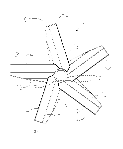
Figure 1 is a top-view illustration of an impeller according to the invention.
Figure 2 is a three-dimensional side-view illustration of an impeller
according
to the invention.
Figure 3 is a top-view illustration of the blades of an impeller according to
the
invention, seen in an exploded view and in a horizontal cross-section.
Figure 4 is a graphical illustration of the impulse (agitation energy) of a
prior
art impeller and an impeller according to the invention with different
distances from the impeller axis.
DETAILED DESCRIPTION OF INVENTION
The impeller of the invention is meant to be used for the same purpose as
the conventionally known straight-bladed impellers of the field, and other
CA 02753740 2011-08-25
WO 2010/103172 PCT/F12010/050157
7
known energy-efficient impellers of the field. The impeller according to the
invention can be used for example in large arrangements, instead of the old
conventional impellers.
With respect to the reactions taking place in a reactor, it is important that
the
impeller according to the invention forms a so-called wake area. In that way
there is achieved a larger area for metallurgical reactions, which often
require turbulence in order to take place.
It has been detected that by means of an impeller according to the invention,
there is achieved, with respect to the prior art, a more even energy
distribution and a larger wake area with turbulence, i.e. the energy
distribution created by the impeller in the reactor is more even. The result
is
a gentle, but at the same time sufficiently efficient agitation for the
reactions
and the mixing of the solids.
In a basic impeller, represented for example by a so-called A-model impeller,
provided with four straight blades, the agitation energy is strongly bound in
the energy peaks created around the impeller blade. The Gaussian curve of
the energy distribution of an impeller according to the invention has a
remarkably lower gradient, because the aim has been to avoid the peaks.
An impeller according to the invention can be compared to an A-model
impeller, where the angle of the impeller blades is 45 degrees. In the
development of the new impeller, the aim has been to observe the
phenomena taking place in a reactor as a whole, so that the object is a
process result as good as possible. In addition to the amount of agitation
created by the impeller, attention has been paid to the effects of the
agitation
in the reactions required by the ongoing process.
The total agitation of the process solution in the reactor, caused by the
impeller, can be estimated by means of the degree of pumping caused by
CA 02753740 2011-08-25
WO 2010/103172 PCT/F12010/050157
8
the impeller. Pumping here means the mobile liquid volume in the reactor at
various height levels. When comparing an impeller according to the invention
for example with a basic axial turbine known in the field, provided with four
straight blades with an inclination of 45 degrees, a better pumping rate is
achieved by an impeller according to the invention, by applying the same
speed of rotation. The difference in the pumping rate of said impellers, with
advantage to the impeller according to the invention, is largest in the bottom
region, which is particularly important in the agitation of solids.
The impeller according to the invention is also suited for gas dispersion in a
process solution, up to a certain limit, but it is not particularly designed
for
this purpose of usage. Here the term `dispersion' means breaking up the gas
to be fed in the reactor, in as small bubbles as possible, and distributing
them as evenly as possible along the whole area of the reactor.
In addition to good mixing properties, the design of an impeller according to
the invention also aims at strength-technical properties that are as good as
possible. In this way, there are achieved advantages both with respect to
expenses and to the manufacturing process.
The profile of an impeller according to the invention is realized by two
parallel folds, which technique differs from the generally applied system of
one fold, or a continuously changing profile (hydrofoil). In the impeller
according to the invention, the impeller profile extends as long as the axis,
and owing to this feature, there is achieved a natural rigidity.
The structural rigidity of an impeller according to the invention is about
twenty times as high as that of a straight-bladed impeller. Even if the
structure of a straight-bladed impeller is reinforced, the fatigue durability
of
the joint between the blade and the hub in a straight-bladed impeller always
remains lower than that of an impeller according to the invention. Said joint
is
the most universal factor for defining the working life of the impeller. The
CA 02753740 2011-08-25
WO 2010/103172 PCT/F12010/050157
9
rigidity of the structure reduces the extension of each stress cycle, which
naturally prevents fatigue breakdown.
When comparing a straight-bladed impeller and an impeller according to the
invention on different levels of the reactor, it was detected that by means of
an impeller according to the invention, there is achieved the same pumping
efficiency with a power consumption that is even 50% lower. This can be
directly calculated as savings in operation expenses for the customer using
the impeller. A more durable structure of the impeller also enables a longer
working life and a lesser need for maintenance.
By using an impeller according to the invention, there are achieved savings
in the manufacturing expenses. A lesser need of power enables the use of a
smaller motor, and consequently perhaps the use of a lighter gearbox and a
lighter structure for the impeller axis. It is also possible to arrange
several
new impellers according to the invention simultaneously on the same axis,
because the impellers render an even agitation and enable a smooth flow.
The manufacture of an impeller according to the invention is cheaper than for
example the manufacture of the impeller described in the prior art, because
there is no need for a separate bracketed hub for the impeller axis.
As is apparent from Figures 1, 2 and 3, the impeller 1 according to the
invention is formed of blades 2, which are fastened to the axis 3, or possibly
by means of a hub (not illustrated in more detail). The joint 13 of the blades
is made directly either in the axis or in the hub, without any brackets or a
bolt
joint. A typical way for realizing the junction is welding. Thus, the most
generally applied ways for realizing said joint in the field are welding
directly
to the hub or axis, or a bolt joint to a bracket welded in the axis or hub.
Basically an impeller according to the invention comprises as many blades
as can be fastened to the axis, i.e. 5 - 7, preferably 5.
CA 02753740 2011-08-25
WO 2010/103172 PCT/F12010/050157
In an impeller according to the invention, the blade 2 is provided with two
folds that are in parallel with the longitudinal direction on the blade, i.e.
with
the blade front edge 4, a first fold 5 and a second fold 6, which are located
at
essentially the same distance from each other and extend from the blade
5 root 7 to the blade tip 8. The rounder the blade fold is, the better and
more
efficiently it functions in practice. The profile to be formed in the blade is
made by these two folds, which divide the impeller blade into three profiles
that are equal in width, the surface area of said blades, however, being
reduced in the rotary direction of the blade. In a normal case, the blade
front
10 edge 4 is horizontal, and by means of folds, the blade is made to bend
downwardly. The angle of each fold with respect to the horizontal plane is 15
- 25 , preferably 20 . When the blade front edge 4 is horizontal, the
inclination of the first blade profile 9 of the blade is 15 - 25 from the
front
edge, the central inclination is approximately 20 , the inclination of the
centermost blade profile 10 is of the order 35 - 45 , the central inclination
being preferably 40 , and the inclination of the third blade profile 11 being
of
the order 55 - 65 , the central inclination being preferably 60 from the
blade
front edge. Now the whole central inclination of the blade is of the order 40
.
The blade front edge 4 can also be inclined by a maximum of 10 degrees
upwardly or downwardly, in which case the whole central inclination of the
impeller, with respect to the horizontal plane, is of the order 30 - 50 , but
with respect to the impeller front edge still of the order 40 .
From Figure 3 it can be seen that the blade 2 of an impeller according to the
invention is made of a plate with a homogeneous structure, and the front
edge 4 of said plate, when viewed in the rotary direction, is straight, but
the
trailing edge, i.e. the rear edge 12, is chamfered so that the blade is
narrowed towards the tip 8. The angle of the trailing edge with respect to the
straight front edge is a, which is of the order 15 - 25 , i.e. the blade is
trapezoid-shaped.
CA 02753740 2011-08-25
WO 2010/103172 PCT/F12010/050157
11
The tip of the blade is at right angles to the front edge, i.e. it is
straight. The
same applies to the blade root, but when necessary, it can be shaped in
order to suitably fasten it to the axis 3. A homogeneous structure here
means that the blade is not chamfered or otherwise shaped in the direction
of the thickness. Because the trailing edge 12 is chamfered, it means that all
blade profiles 9, 10 and 11 are different in size. The surface area of the
first
blade profile 9 is largest, and the surface area of the third profile 11 is
smallest.
The fairly large total angle provided in the blade according to the invention
essentially improves the structural rigidity of the impeller. Moreover, the
blade is narrowed when proceeding from the axis 3, from the blade root 7
towards the blade tip 8. With a narrowing structure, energy is distributed
more evenly, because the face area is reduced as the pitch line velocity
increases.
In an impeller according to the invention, the characteristic features are not
based on radial concavity. When both folds in an impeller according to the
invention extend as far as the impeller axis, the structure becomes more rigid
than in an impeller where the blades are fastened by means of bolts.
In an impeller according to the invention, the wear-resistance of the blade
structure is based on blades that are permanently attached to an axis or a
detachable hub. The natural rigidity is based on the fact that the center
point
of so-called inertia is shifted further from the fastening line, and the load
per
each blade is reduced, as the number of blades is increased.
An impeller 1 according to the invention aims at minimizing the power
consumed for creating the axial flow, so that the micromixing needed by the
reactions need not be taken into account, and thus the object of an impeller
1 according to the invention is also to ensure a sufficient reaction rate,
i.e. it
CA 02753740 2011-08-25
WO 2010/103172 PCT/F12010/050157
12
aims at securing the functional efficiency of the whole process, not only of
the agitation step.
By means of an impeller 1 according to the invention, the Gaussian curve of
the energy distribution has a remarkably lower gradient, because the aim
has been to avoid the peaks. This is also described below and explained
with reference to a separate example 1.
In processes where energy peaks break up flocculants, agglomerates or
drops, the capacity for recovery of the product or waste to be separated from
the process solution is essentially weakened. On the other hand, in
processes where the reaction rate is proportional to the agitation energy up
to a certain saturation point, energy is saved by using an impeller 1
according to the invention, because unnecessary energy peaks are not
generated in the process, but the agitation energy is distributed as evenly as
possible throughout the whole reactor volume.
EXAMPLES
Example 1
In Figure 4, the impulse distribution, i.e. agitation energy distribution, of
an
impeller according to the invention is compared with that of an impeller
according to the prior art (US 5,052,892) by means of graphic diagrams. In
the diagrams, there is calculated the impulse given by the impeller blade with
different distances from the impeller axis, when the maximum length of the
blade is 85 mm.
In the diagrams, the employed surface area of the impeller blades has been
one and the same in each case. From the diagrams it can be seen that the
impulse given by a prior art impeller blade is very strong at the blade tip,
whereas in an impeller according to the invention, the impulse is remarkably
CA 02753740 2011-08-25
WO 2010/103172 PCT/F12010/050157
13
more even along the whole length of the blade. When there is desired an
even agitation into the reactor, the model of the impeller blade according to
the invention is clearly more advantageous than the one described in the
prior art.