Language selection

Search

Patent 2753764 Summary

Third-party information liability

Some of the information on this Web page has been provided by external sources. The Government of Canada is not responsible for the accuracy, reliability or currency of the information supplied by external sources. Users wishing to rely upon this information should consult directly with the source of the information. Content provided by external sources is not subject to official languages, privacy and accessibility requirements.

Claims and Abstract availability

Any discrepancies in the text and image of the Claims and Abstract are due to differing posting times. Text of the Claims and Abstract are posted:

  • At the time the application is open to public inspection;
  • At the time of issue of the patent (grant).
(12) Patent Application: (11) CA 2753764
(54) English Title: PRESSURIZED LIQUID DISPENSING SYSTEM
(54) French Title: SYSTEME DE DISTRIBUTION DE LIQUIDE SOUS PRESSION
Status: Deemed Abandoned and Beyond the Period of Reinstatement - Pending Response to Notice of Disregarded Communication
Bibliographic Data
Abstracts

Sorry, the abstracts for patent document number 2753764 were not found.

Claims

Note: Claims are shown in the official language in which they were submitted.
Sorry, the claims for patent document number 2753764 were not found.
Text is not available for all patent documents. The current dates of coverage are on the Currency of Information  page

Description

Note: Descriptions are shown in the official language in which they were submitted.


CA 02753764 2011-09-30
PRESSURIZED LIQUID DISPENSING SYSTEM
This invention is in the field of liquid dispensing systems and in particular
a dispensing
system for dispensing liquid from a container under pressure.
BACKGROUND
A wide range of liquids, for example lubricating liquid, paint, insect
repellant, personal
hygiene products such as deodorant, and the like are sold in dispensing
containers which
include some means for expelling the liquid from the container under some
pressure. A
manual pump can be provided for example, but the pump must be constantly
operated by
a linger to maintain a spray.
Aerosol spray cans contain a propellant gas, usually the vapor of a liquid
with boiling
point slightly lower than room temperature. Inside the pressurized can, the
vapor can
exist in equilibrium with its bulk liquid at a pressure that is higher than
atmospheric
pressure (and able to expel the liquid product), but not dangerously high. As
gas escapes,
it is immediately replaced by evaporating liquid. A valve at the top of the
can is
connected to a tube extending down to the bottom of the can. Pressure in the
top of the
can forces the liquid up through the tube when the valve is opened.
Such aerosol cans will not spray when turned upside down, the discharge is
generally
cold, and the propellant gases are often flammable, creating a risk of fire
and injury or
damage.
Alternatively, the bag-on-valve system separates the liquid product from the
propellant
gas inside a sealed pouch which is connected to the valve. The pressure
squeezes the
pouch so that only pure liquid product is dispensed. The bag-on-valve has the
benefits of
benefits upside down spraying, and is the discharge is quiet and non-chilling.
1

CA 02753764 2011-09-30
SUMMARY OF THE INVENTION
It is an object of the present invention to provide a liquid dispensing system
that
overcomes problems in the prior art.
The present invention provides a liquid dispensing system comprising a
housing, and a
collapsible liquid container mounted inside the housing. The container is
connected to a
valve and nozzle at the top of the housing, and a bias element exerts a bias
force on the
container that urges the container toward a collapsed configuration, such that
liquid in the
container is under pressure. When the valve is opened the liquid is forced out
through the
nozzle.
DESCRIPTION OF THE DRAWINGS
While the invention is claimed in the concluding portions hereof, preferred
embodiments
are provided in the accompanying detailed description which may be best
understood in
conjunction with the accompanying diagrams where like parts in each of the
several
diagrams are labeled with like numbers, and where:
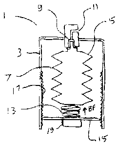
Fig. I is a schematic sectional side view of an embodiment of a liquid
dispensing
apparatus of the present invention shown with the collapsible container full
of liquid
and in an expanded position;
Fig. 2 is a schematic sectional side view of the embodiment of Fig. I shown
with the
collapsible container with a substantially quantity of liquid expelled
therefrom, and in
a collapsed position.
DETAILED DESCRIPTION OF THE ILLUSTRATED EMBODIMENTS
2

CA 02753764 2011-09-30
Figs. I and 2 illustrate schematic sectional side views of an embodiment of a
liquid
dispensing apparatus 1 of the present invention. The apparatus I comprises a
cylindrical
housing 3, and a collapsible liquid container 5 mounted inside the housing 3.
The
illustrated container 5 is collapsible in the vertical direction. The
accordion ridges 7
move together when a force is exerted between the top and bottom ends of the
container
5. The container is typically made from semi-rigid plastic and would of course
be
collapsible in any direction given sufficient force, but the container 5 is
designed to
collapse vertically as described.
The container 5 is connected to a valve 9 and nozzle I I at the top of the
housing 3,
substantially as is known in the prior art. A bias element, illustrated as
compression
spring 13, exerts a vertical bias force BF on the container 5 that urges the
container 5
from the expanded position of Fig.1 toward the collapsed position of Fig. 2.
The bias force BF exerted on the collapsible container 5 puts the liquid in
the container
under pressure, such that when the valve 9 is opened the liquid is forced out
through the
nozzle 11.
It is contemplated that other configurations of collapsible container with a
bias element
pushing the container toward whatever the collapsed position might be, could
be used as
well.
The housing 3 of the illustrated apparatus 1 also has a movable circular floor
IS with an
outer edge engaging threads 17 in the inner surface of the vertical wall of
the housing 3.
As the spring 13 extends as liquid is drawn off and the container 5 collapses,
the bias
force, and therefore the pressure under which the liquid is expelled, may be
reduced. To
maintain the pressure the floor 15 can be rotated with knob 19 to move the
floor 15 up
and compress the spring 13. It is further contemplated that a coil spring
could be
provided to automatically rotate the floor to maintain pressure for a longer
time without
adjusting the floor manually with the knob 19
3

CA 02753764 2011-09-30
To reduce waste and cost it is further contemplated that when the container is
empty, the
floor 15 could be removed and a new "refill" container which is full of the
desired liquid
could be inserted into a seal 21 at the top of the housing 3 at the valve 9.
The apparatus requires no gas propellant, and will dispense liquid from the
container in
any orientation such as upside down. Only the desired liquid is dispensed from
the
nozzle, and at room temperature, with no flammable gas or the like mixed with
the liquid.
The foregoing is considered as illustrative only of the principles of the
invention.
Further, since numerous changes and modifications will readily occur to those
skilled in
the art, it is not desired to limit the invention to the exact construction
and operation
shown and described, and accordingly, all such suitable changes or
modifications in
structure or operation which may be resorted to are intended to fall within
the scope of
the claimed invention.
4

Representative Drawing
A single figure which represents the drawing illustrating the invention.
Administrative Status

2024-08-01:As part of the Next Generation Patents (NGP) transition, the Canadian Patents Database (CPD) now contains a more detailed Event History, which replicates the Event Log of our new back-office solution.

Please note that "Inactive:" events refers to events no longer in use in our new back-office solution.

For a clearer understanding of the status of the application/patent presented on this page, the site Disclaimer , as well as the definitions for Patent , Event History , Maintenance Fee  and Payment History  should be consulted.

Event History

Description Date
Application Not Reinstated by Deadline 2014-04-22
Inactive: Dead - Application incomplete 2014-04-22
Deemed Abandoned - Failure to Respond to Maintenance Fee Notice 2013-09-30
Deemed Abandoned - Failure to Respond to Notice Requiring a Translation 2013-04-22
Inactive: Cover page published 2013-04-11
Application Published (Open to Public Inspection) 2013-03-30
Inactive: Incomplete 2013-01-22
Inactive: First IPC assigned 2012-05-28
Inactive: IPC assigned 2012-05-28
Filing Requirements Determined Compliant 2011-10-14
Reinstatement Requirements Deemed Compliant for All Abandonment Reasons 2011-10-14
Inactive: Filing certificate - No RFE (English) 2011-10-14
Application Received - Regular National 2011-10-14
Small Entity Declaration Determined Compliant 2011-09-30

Abandonment History

Abandonment Date Reason Reinstatement Date
2013-09-30
2013-04-22

Fee History

Fee Type Anniversary Year Due Date Paid Date
Application fee - small 2011-09-30
Owners on Record

Note: Records showing the ownership history in alphabetical order.

Current Owners on Record
BRANT FRIESEN
Past Owners on Record
None
Past Owners that do not appear in the "Owners on Record" listing will appear in other documentation within the application.
Documents

To view selected files, please enter reCAPTCHA code :


To view images, click a link in the Document Description column. To download the documents, select one or more checkboxes in the first column and then click the "Download Selected in PDF format (Zip Archive)" or the "Download Selected as Single PDF" button.

List of published and non-published patent-specific documents on the CPD .

If you have any difficulty accessing content, you can call the Client Service Centre at 1-866-997-1936 or send them an e-mail at CIPO Client Service Centre.


Document
Description 
Date
(yyyy-mm-dd) 
Number of pages   Size of Image (KB) 
Claims 2013-03-29 1 3
Abstract 2013-03-29 1 3
Description 2011-09-29 4 119
Drawings 2011-09-29 1 10
Representative drawing 2012-09-20 1 7
Filing Certificate (English) 2011-10-13 1 156
Reminder of maintenance fee due 2013-06-02 1 114
Courtesy - Abandonment Letter (incomplete) 2013-06-16 1 165
Courtesy - Abandonment Letter (Maintenance Fee) 2013-11-24 1 172
Correspondence 2011-10-13 1 27
Correspondence 2013-01-21 1 28