Language selection

Search

Patent 2753819 Summary

Third-party information liability

Some of the information on this Web page has been provided by external sources. The Government of Canada is not responsible for the accuracy, reliability or currency of the information supplied by external sources. Users wishing to rely upon this information should consult directly with the source of the information. Content provided by external sources is not subject to official languages, privacy and accessibility requirements.

Claims and Abstract availability

Any discrepancies in the text and image of the Claims and Abstract are due to differing posting times. Text of the Claims and Abstract are posted:

  • At the time the application is open to public inspection;
  • At the time of issue of the patent (grant).
(12) Patent: (11) CA 2753819
(54) English Title: THERMALLY DECOUPLED BEARING ARRANGEMENT
(54) French Title: AGENCEMENT DE PALIER DECOUPLE THERMIQUEMENT
Status: Expired and beyond the Period of Reversal
Bibliographic Data
(51) International Patent Classification (IPC):
  • F16C 17/22 (2006.01)
  • F04D 29/046 (2006.01)
  • F16C 33/04 (2006.01)
  • F16J 15/34 (2006.01)
(72) Inventors :
  • PFEIL, DIETER (Germany)
  • SCHERER, HANS-GEORG (Germany)
  • RAUH, GISELA (Germany)
(73) Owners :
  • EAGLEBURGMANN GERMANY GMBH & CO. KG
(71) Applicants :
  • EAGLEBURGMANN GERMANY GMBH & CO. KG (Germany)
(74) Agent: MILLMAN IP INC.
(74) Associate agent:
(45) Issued: 2014-12-30
(86) PCT Filing Date: 2010-03-11
(87) Open to Public Inspection: 2010-09-30
Examination requested: 2011-08-26
Availability of licence: N/A
Dedicated to the Public: N/A
(25) Language of filing: English

Patent Cooperation Treaty (PCT): Yes
(86) PCT Filing Number: PCT/EP2010/001541
(87) International Publication Number: EP2010001541
(85) National Entry: 2011-08-26

(30) Application Priority Data:
Application No. Country/Territory Date
20 2009 004 160.3 (Germany) 2009-03-25

Abstracts

English Abstract


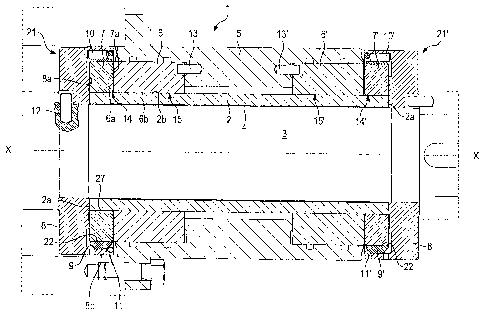
The invention relates to a bearing arrangement for supporting a shaft (3),
comprising
a bushing (2) in which the shaft (3) is received, a circumferential ring gap
(4) being present
between the bushing (2) and the shaft (3), and the bushing (2) and the shaft
(3) being
made of materials having different thermal expansion coefficients, a
connection
arrangement (21) comprising a retaining element (8; 32, 33, 34) connected to
the shaft (3)
and a rotating bearing ring (7) in order to provide a centering support of the
bushing (2) at
the outer circumference (2b) thereof relative to the shaft (3), a stationary
bearing ring (6, 6')
that is disposed radially outside of the bushing (2) and forms an axial
sliding bearing (14)
with the rotating bearing ring (7, 7'), and is characterized in that the
connection
arrangement (21) comprises a circumferential annular band element (9, 9'),
wherein the
annular band element (9, 9') is connected to the rotating bearing ring (7, 7')
by means of a
shrinkage connection in order to form an interconnected element (23), wherein
the
interconnected element (23) is inserted in a recess (8a; 32a) of the retaining
element (8;
32) with a centering snug fit, and the annular band element (9, 9') is
connected to the
retaining element (8; 32) in the axial direction (X-X) of the shaft (3).


French Abstract

L'invention concerne un agencement de palier destiné à recevoir un arbre (3), avec un coussinet (2) dans lequel l'arbre (3) est reçu, une fente annulaire (4) se situant entre le coussinet (2) et l'arbre (3) et le coussinet (2) et l'arbre (3) étant fabriqués dans des matériaux ayant des coefficients de dilatation thermique différents, avec un agencement de liaison (21) qui comprend un élément de maintien (8 ; 32, 33, 34) relié à l'arbre (3) et une bague de palier (7) rotative, afin de réaliser un appui centré du coussinet (2) sur sa circonférence extérieure (2b) par rapport à l'arbre (3), avec une bague de palier stationnaire (6, 6') qui est disposée radialement en dehors du coussinet (2) et qui, avec la bague de palier rotative (7, 7'), forme un palier lisse axial (14). L'agencement de palier selon l'invention est caractérisé en ce que l'agencement de liaison (21) comprend un élément annulaire (9, 9'). L'élément annulaire (9, 9') est relié à la bague de palier rotative (7, 7') par un assemblage fretté (22) afin de former un élément composite (23). L'élément composite (23) est inséré par un montage ajusté dans un logement (8a ; 32a) de l'élément de maintien (8 ; 32) et l'élément annulaire (9, 9') est relié avec l'élément de maintien (8 ; 32) dans la direction axiale (X-X) de l'arbre (3).

Claims

Note: Claims are shown in the official language in which they were submitted.


9
Claims
1. A bearing arrangement for supporting a shaft, comprising
- a bushing in which the shaft is received, a circumferential ring gap being
present between the bushing and the shaft, and the bushing and the shaft
being made of materials having different thermal expansion coefficients,
- a connection arrangement comprising a retaining element connected to the
shaft and a rotating bearing ring in order to provide a centering support of
the
bushing at the outer circumference thereof relative to the shaft,
- a stationary bearing ring that is disposed radially outside of the
bushing and
forms an axial sliding bearing with the rotating bearing ring,
- the connection arrangement comprising a circumferential annular band
element that is connected to the rotating bearing ring by a shrinkage
connection to form an interconnected element, the interconnected element
inserted in a recess of the retaining element with a centering snug fit having
no
tolerance or a slight tolerance on the order of pm, the annular band element
connected to the retaining element in the axial direction of the shaft, the
annular band element, the retaining element and the shaft made of a material
having the same or a similar thermal expansion coefficient, and the bushing,
the rotating bearing ring and the stationary bearing ring made of a material
having the same or a similar thermal expansion coefficient.

10
2. The bearing arrangement of claim 1, wherein the annular band element is
symmetric with an axis that is arranged perpendicular to the axial direction
of the
shaft.
3. The
bearing arrangement of claim 1 or 2, wherein the bushing, the rotating bearing
ring and the stationary bearing ring are made of SiC.
4. The bearing arrangement of any one of claims 1 to 3, wherein the retaining
element, the shaft and the annular band element are made of steel.
5. The bearing arrangement of any one of claims 1 to 4, wherein the stationary
bearing ring has a radial sliding surface and forms a radial sliding bearing
together
with a radial sliding surface of the bushing.
6. The bearing arrangement of any one of claims 1 to 5, wherein two stationary
bearing rings and two rotating bearing rings form a twin bearing arrangement.

11
7. The bearing arrangement of claim 6, wherein the rotating bearing rings are
arranged at stationary bearing ring sides facing each other in the axial
direction of
the shaft.
8. The bearing arrangement of claim 6, wherein the rotating bearing rings are
arranged at stationary bearing ring sides facing away from each other in the
axial
direction (X-X) of the shaft.
9. A
magnetic coupling comprising a bearing arrangement of any one of claims 1 to
8.

Description

Note: Descriptions are shown in the official language in which they were submitted.


CA 02753819 2011-08-26
THERMALLY DECOUPLED BEARING ARRANGEMENT
Specification
[0001]The invention refers to a bearing arrangement for supporting a shaft,
which is made
of components having different thermal expansion coefficients, wherein the
bearing
arrangement comprises a thermal decoupling.
[0002]Bearing arrangements of different kinds are known from the state of the
art. In
particular in case of sliding bearings, it is often desired that a bearing
insert of the sliding
bearing is made of a wear-resistant material, e.g. a ceramic material, for
reducing wear.
When such a bearing insert co-operates with a shaft which is e.g. made of a
steel material,
problems may occur due to the thermal expansion coefficient of steel, which is
much higher
compared to that of the ceramic material. This may result in damages at the
bearing
arrangement.
[0003]From EP 0 563 437 A2, a bearing arrangement is known, in which a ceramic
bushing is supported in a centering manner opposite to a shaft at an outer
periphery of the
bushing by means of a counter-bearing arrangement. This bearing arrangement
basically
has proven of value and is e.g. used for rotary pumps. Currently, however,
increased
requirements concerning the load capacity arose, and in particular the
diameters of the
shafts are made larger due to the high demand for larger equipment. Further,
speed-
controlled machines are more and more used, such that different duty points
with different
heat generation occur due to the speed control. Therewith, it is not possible
to adapt the
bearing arrangement for just one duty point.

CA 02753819 2011-08-26
2
[0004]lt is therefore an object underlying the present invention to provide a
bearing
arrangement which secures a safe operation also upon regular speed changes of
a shaft
while having a simple structure and being manufactured easily and at low
costs.
[0005]This object is solved by a bearing arrangement having the features of
claim 1. The
sub-claims comprise advantageous further developments of the invention.
[0006]The inventive bearing arrangement having the features of claim 1 has the
advantage
that it enables a thermal decoupling at the bearing, such that the individual
components of
the bearing arrangement can be made of materials having different thermal
expansion
coefficients. Therewith, the materials for the individual components can be
adapted
optimally to the respective requirements. According to the invention, a
structure of the
bearing arrangement can be very simple and cost-effective. According to the
invention, this
is achieved by shrink-fitting a band element onto an outer periphery of a
rotating bearing
ring such that a shrinkage connection is provided between the band element and
the
rotating bearing ring. Thus, the rotating bearing ring together with the
shrink-fitted band
element forms an interconnected element which is inserted into a recess of a
retaining ring
with a centering snug-fit. According to the invention, a centering snug-fit is
a fit having no
tolerance or a slight tolerance in the order of m. Therewith, no press-fit
may be present.
The interconnected element may thus be inserted into and removed from the
recess of the
retaining ring manually. The band element is connected to the retaining ring
by means of
an axial connection. Herein, the interconnected element is at least partially
surrounded by
the retaining element in the radial direction, wherein the thermal decoupling
between the
interconnected element and the retaining element is enabled due the insertion
of the
interconnected element into the retaining element with a centering snug-fit. A
stationary
bearing ring and a rotating bearing ring form an axial sliding bearing.
Therewith, undesired

CA 02753819 2011-08-26
3
alterations of the running surface . positions at the axial sliding bearing
due to thermal
alterations can be compensated according to the invention. Therewith, a damage
of the
running surfaces by a so-called edge loading can be prevented.
[0007] Particularly preferred, the stationary bearing ring additionally has a
sliding surface
that is directed radially inwardly, in order to form a radial sliding bearing
together with the
bushing that surrounds the shaft. Therewith, a radial sliding bearing and an
axial sliding
bearing can simultaneously be provided at the stationary bearing ring. Due to
this multiple
surface support at the stationary bearing ring, in particular the number of
components can
be reduced and a compact bearing arrangement can be provided.
[0008] Particularly preferred, the band element is formed symmetrically with
respect to an
axis disposed perpendicular with respect to a center axis of the shaft.
Therewith, it is
guaranteed that a constant alteration of the dimensions occur upon temperature
changes
at the band element. In this context, the band element preferably comprises a
large bevel
at the two edge portions directed radially outwardly.
[0009] Particularly preferred, the bearing arrangement is formed as a twin
bearing
arrangement and therewith comprises two rotating bearing rings and two
stationary bearing
rings. Therewith, the shaft can be supported at two mutually spaced regions.
Preferably,
the rotating bearing rings are arranged at stationary bearing ring sides
facing each other in
the axial direction for this purpose. In other words: In the axial direction,
the rotating
bearing rings are arranged between the stationary bearing rings. As an
alternative, the
rotating bearing rings are arranged at stationary bearing ring sides facing
away from each
other in the axial direction. In other words: In the axial direction, the
stationary bearing rings
are arranged between the rotating bearing rings.

CA 02753819 2011-08-26
4
[0010]Further, the present invention relates to a magnetic coupling including
the inventive
bearing arrangement. Magnetic couplings are preferably used in speed-
controlled
machines, in particular in pumps.
[0011]ln the following, the present invention is described in detail on the
basis of preferred
embodiments in connection with the accompanying drawing, in which:
Fig. 1 shows a schematic sectional view of a bearing arrangement according to
a
first embodiment of the invention,
Fig. 2 shows a schematic sectional view of a connection arrangement of Fig. 1,
Fig. 3 shows a schematic sectional view of a rotary pump which uses a bearing
arrangement according to Fig. 1, and
Fig. 4 shows a schematic sectional view of a bearing arrangement according to
a
second embodiment of the invention.
[0012]ln the following, a bearing arrangement 1 according to a first
embodiment of the
invention is described in detail with reference to Figs. 1 to 3. As is
discernible from Fig. 1,
the bearing arrangement 1 comprises a cylindrical bushing 2 in which a shaft 3
is arranged.
A ring gap 4 is provided between the bushing 2 and the shaft 3, such that a
radial distance
is present between the bushing 2 and the shaft 3. The dimension of the ring
gap 4 is
selected such that a thermal expansion behaviour of the shaft 3 is considered,
since the
shaft 3 and the bushing 2 are made of different materials. In the present
embodiment, the
shaft is made of a steel material and the bushing is made of a ceramic
material (SiC).
[0013]The bearing arrangement 1 of the shown embodiment serves to
simultaneously
support the shaft 3 axially as well as radially. In this case, the bearing
arrangement 1 is
provided as a twin bearing for supporting the shaft 3 at two mutually spaced
regions. For
this purpose, the bearing arrangement comprises a pair of axial sliding
bearings 14, 14'

CA 02753819 2011-08-26
and a pair of radial sliding bearings 15, 15'. The axial sliding bearings 14,
14' respectively
comprise a rotating bearing ring 7, 7' as well as a stationary bearing ring 6,
6'. The radial
sliding bearings 15, 15' are formed in the radial direction of the shaft
between the
stationary bearing ring 6, 6' and an outer boundary 2b of the bushing 2. As is
discernible
5 from Fig. 1, the two stationary bearing rings 6, 6' are attached to a
housing part 5 by
means of pins 13, 13'.
[0014]The shaft 3 is connected to the bushing 2 at the two opposing ends of
the bushing 2
by means of connection or centering arrangements 21, 21'. The connection
arrangements
21, 21' serve to concentrically position the bushing 2 relative to the shaft
3. Each of the
connection arrangements 21, 21' comprises an annular retaining element 8, 8'
which is
connected to the shaft 3 by means of pins 12. Further, also the rotating
bearing rings 7, 7'
are part of the connection arrangements 21, 21'. As is in particular
discernible from Fig. 2,
the connection arrangements 21, 21' further comprise an additional annular
band element
9, 9'. The annular band element 9, 9' is formed symmetrically with respect to
an axis A,
wherein the axis A is perpendicular to a center axis or rotation axis X-X of
the shaft 3. The
annular band element 9, 9' is made of a metallic material and is respectively
shrunk-fit onto
the rotating bearing rings 7, 7' by means of a shrinkage connection 22, 22',
which bearing
rings are made of a ceramic material. Therewith, the rotating bearing rings 7,
7' and the
annular band elements 9, 9' respectively form an interconnected element 23
(Fig. 2). The
annular band element 9, 9' is connected to the annular retaining element 8, 8'
in the axial
direction through a fixing pin 10, 10'. As is shown in Fig. 2, the annular
retaining element 8
has a recess 8a which is delimited by an annular rim portion 8b in a radially
outward
direction. Herein, the interconnected element 23, comprising the rotating
bearing ring 7 and
the annular band element 9, is inserted into the recess 8a with a centering
snug-fit, and is

CA 02753819 2011-08-26
6
connected to the annular retaining element 8 in the axial direction only by
the fixing pin 10.
Therewith, the rotation of the shaft 3 is transmitted through the annular
retaining element 8,
the fixing pin 10 and the annular band element 9 to the rotating bearing ring
7. The rotating
bearing ring 7, at the inner periphery thereof, is still connected to the
bushing 2 through a
connection 27, in particular a centering snug-fit, wherein the bushing 2 is
preferably
clamped in an axial direction between the retaining elements 8, 8'. Therewith,
the bushing
2 is centered at the shaft 3 by means of the connection arrangement 21, such
that the shaft
3 and the bushing 2 can be made of materials having different thermal
expansion
coefficients without any problem.
[0015] The annular band element 9 further comprises large bevels 9a, 9b at its
edge
portions directed radially outwardly, wherein these bevels are also formed
symmetrically
with respect to the axis A. For attaching the interconnected element 23, a
snap ring 11 is
provided at the bevel 9b of the annular band element 9, which snap ring is
retained in a
recess in the rim portion 8b.
[0016] Therewith, a thermal decoupling between the components having different
thermal
expansion coefficients can be achieved according to the invention. Besides the
shaft 3,
also the annular retaining element 8 as well as the annular band element 9 are
made of a
metallic material. Contrary thereto, the rotating bearing ring 7 and the
bushing 2 are made
of a ceramic material. Consequently, the rotating bearing 7 does not react
with a tipping
when the temperature changes, which can result in the wear occurring in the
state of the
art at the axial sliding surfaces 7a, 6a of the axial sliding bearings 14,
14'. Changes of the
tension profile in the shrinkage connection 22 between the annular band
element 9 and the
rotating bearing ring 7 can be compensated by the interconnected element 23
being
inserted with the centering snug-fit. Due to the symmetric design of the
annular band

CA 02753819 2011-08-26
7
element 9 with respect to the axis A, in particular, no tipping of the
rotating bearing ring 7
occurs upon different thermal expansions of the individual components.
[0017]Fig. 3 shows the use of the inventive bearing arrangement 1 in a pump.
The pump
comprises a magnetic coupling 16 including driving magnets 17 and driven
magnets 18. A
split cup 19 is provided between the driving magnets 17 and the driven magnets
18. The
driven magnets 18 are herein connected to the shaft 3. A pump wheel is
designated with
reference numeral 20. The inventive bearing arrangement 1 assumes the axial as
well as
the radial support of the shaft 3, wherein two bearing surfaces, i. e. one
bearing surface in
the axial direction and one bearing surface in the radial direction, are
provided at the
stationary bearing rings 6, 6'.
[0018]Fig. 4 shows a bearing arrangement 1 according to a second embodiment of
the
invention, wherein identical or functionally identical components have the
same reference
numerals as in the first embodiment. The bearing arrangement 1 of the second
embodiment substantially corresponds to that of the first embodiment, wherein
the
arrangement of the stationary bearing rings 6, 6' with respect to the rotating
bearing rings
7, 7' is reversed compared to the first embodiment. In the second embodiment,
the rotating
bearing rings 7, 7' are arranged at sides of the stationary bearing rings 6,
6' facing away
from each other in the axial direction. Further, no continuous bushing is
provided in the
second embodiment, but two separate bushings 30, 31. The two bushings 30, 31
are
connected to each other through an intermediate element 32. Further, the first
bushing 30
is connected to the shaft 3 through a retaining element 33 and the second
bushing 31 is
connected to the shaft 3 through a retaining element 34. The annular band
elements 9, 9'
are again shrunk-fitted onto the rotating bearing rings 7, 7' and fixedly
connected to the
intermediate element 32 in the axial direction by means of fixing pins 10,
10'. The rotating

CA 02753819 2011-08-26
8
bearing rings 7, 7' as well as the two bushings 30, 31 are again made of a
ceramic
material, and the intermediate element 32 and the two retaining elements 33,
34 as well as
the shaft 3 are made of a metallic material, such that these components again
have
different thermal expansion coefficients. Also in this embodiment, the
rotating bearing rings
7, 7' and the annular band elements 9, 9' again form an interconnected element
23 by
means of shrinkage connections, which interconnected element is inserted into
the
intermediate element 32 with a centering snug-fit. A fixation of the
interconnected element
23 in the axial direction for transmitting the torque occurs only through the
fixing pins 10,
10'. Apart from this, the present embodiment corresponds to the preceding
embodiment,
such that reference can be made to the description given therein.

Representative Drawing
A single figure which represents the drawing illustrating the invention.
Administrative Status

2024-08-01:As part of the Next Generation Patents (NGP) transition, the Canadian Patents Database (CPD) now contains a more detailed Event History, which replicates the Event Log of our new back-office solution.

Please note that "Inactive:" events refers to events no longer in use in our new back-office solution.

For a clearer understanding of the status of the application/patent presented on this page, the site Disclaimer , as well as the definitions for Patent , Event History , Maintenance Fee  and Payment History  should be consulted.

Event History

Description Date
Inactive: Associate patent agent added 2023-01-27
Revocation of Agent Requirements Determined Compliant 2022-11-23
Appointment of Agent Requirements Determined Compliant 2022-11-23
Time Limit for Reversal Expired 2021-09-13
Letter Sent 2021-03-11
Letter Sent 2020-09-11
Letter Sent 2020-03-11
Common Representative Appointed 2019-10-30
Grant by Issuance 2014-12-30
Inactive: Cover page published 2014-12-29
Pre-grant 2014-10-08
Inactive: Final fee received 2014-10-08
Notice of Allowance is Issued 2014-06-17
Letter Sent 2014-06-17
Notice of Allowance is Issued 2014-06-17
Inactive: Received pages at allowance 2014-06-04
Inactive: Office letter 2014-05-08
Inactive: Approved for allowance (AFA) 2014-04-28
Inactive: Q2 passed 2014-04-28
Maintenance Request Received 2014-02-06
Amendment Received - Voluntary Amendment 2013-12-24
Inactive: S.30(2) Rules - Examiner requisition 2013-06-28
Maintenance Request Received 2013-01-15
Inactive: Cover page published 2011-10-21
Inactive: IPC assigned 2011-10-17
Application Received - PCT 2011-10-17
Inactive: First IPC assigned 2011-10-17
Letter Sent 2011-10-17
Inactive: Acknowledgment of national entry - RFE 2011-10-17
Inactive: IPC assigned 2011-10-17
National Entry Requirements Determined Compliant 2011-08-26
Request for Examination Requirements Determined Compliant 2011-08-26
All Requirements for Examination Determined Compliant 2011-08-26
Application Published (Open to Public Inspection) 2010-09-30

Abandonment History

There is no abandonment history.

Maintenance Fee

The last payment was received on 2014-02-06

Note : If the full payment has not been received on or before the date indicated, a further fee may be required which may be one of the following

  • the reinstatement fee;
  • the late payment fee; or
  • additional fee to reverse deemed expiry.

Patent fees are adjusted on the 1st of January every year. The amounts above are the current amounts if received by December 31 of the current year.
Please refer to the CIPO Patent Fees web page to see all current fee amounts.

Owners on Record

Note: Records showing the ownership history in alphabetical order.

Current Owners on Record
EAGLEBURGMANN GERMANY GMBH & CO. KG
Past Owners on Record
DIETER PFEIL
GISELA RAUH
HANS-GEORG SCHERER
Past Owners that do not appear in the "Owners on Record" listing will appear in other documentation within the application.
Documents

To view selected files, please enter reCAPTCHA code :


To view images, click a link in the Document Description column. To download the documents, select one or more checkboxes in the first column and then click the "Download Selected in PDF format (Zip Archive)" or the "Download Selected as Single PDF" button.

List of published and non-published patent-specific documents on the CPD .

If you have any difficulty accessing content, you can call the Client Service Centre at 1-866-997-1936 or send them an e-mail at CIPO Client Service Centre.


Document
Description 
Date
(yyyy-mm-dd) 
Number of pages   Size of Image (KB) 
Drawings 2011-08-25 4 125
Description 2011-08-25 8 349
Claims 2011-08-25 3 70
Representative drawing 2011-08-25 1 41
Abstract 2011-08-25 1 32
Claims 2013-12-23 2 80
Claims 2014-06-03 3 74
Representative drawing 2014-12-08 1 29
Acknowledgement of Request for Examination 2011-10-16 1 176
Notice of National Entry 2011-10-16 1 202
Courtesy - Certificate of registration (related document(s)) 2011-10-16 1 104
Reminder of maintenance fee due 2011-11-14 1 112
Commissioner's Notice - Application Found Allowable 2014-06-16 1 161
Commissioner's Notice - Maintenance Fee for a Patent Not Paid 2020-04-21 1 545
Courtesy - Patent Term Deemed Expired 2020-10-01 1 548
Commissioner's Notice - Maintenance Fee for a Patent Not Paid 2021-04-26 1 536
Maintenance fee payment 2018-12-03 1 25
PCT 2011-08-25 5 207
Fees 2012-01-24 2 78
Fees 2013-01-14 2 92
Fees 2014-02-05 2 62
Correspondence 2014-05-07 1 22
Correspondence 2014-06-03 4 113
Correspondence 2014-10-07 2 90
Fees 2015-01-06 1 25
Fees 2016-01-26 1 25
Maintenance fee payment 2017-02-12 1 25
Maintenance fee payment 2018-01-31 1 25