Note: Descriptions are shown in the official language in which they were submitted.
CA 02753951 2011-09-29
241679
METHOD OF OPERATING A REFRIGERATOR
BACKGROUND OF THE INVENTION
The current disclosure relates generally to refrigerators, and more
specifically to a
method of operating refrigerators to facilitate removal of the ice storage
bins from the
refrigerators.
A refrigerator usually has an ice storage bin for storing ice. The ice storage
bins typically
can be removed from the refrigerator if desired, without the removal of a
motor which
drives auger and/or ice crusher within the ice storage bin. The ice storage
bin is typically
coupled to the motor in a dual fork coupling arrangement with one fork being
affixed to
the motor and the other fork being affixed to a generally horizontally
disposed shaft of
the ice storage bin. This ice storage bin is typically secured to the
refrigerator by tabs or
latches. To remove the ice storage bin from the refrigeration, a user needs to
first release
the tab/latch connection by lifting the ice storage bin vertically. Typically,
the fork
affixed to the motor rotates in either direction based on input from a user,
and can stop
rotation whenever the input from the user ends. This stop in operation allows
the forks to
orient themselves in any random point along 360 of rotation. Once the forks
have
stopped rotating, if a portion of one fork is vertically above a portion of
the other fork,
removal of the ice storage bin by a user will be very difficult.
In other words, removal of a typical ice storage bin can be difficult if the
coupling forks
orient themselves in certain positions.
Therefore, a method for removal of an ice storage bin with a dual fork
coupling
arrangement is desired.
1
CA 02753951 2011-09-29
241679
BRIEF DESCRIPTION OF THE INVENTION
As described herein, the exemplary embodiments of the current invention
overcome one
or more of the above or other disadvantages known in the art.
One exemplary aspect of the present invention relates to a method of operating
a
refrigerator including a driving assembly and an ice storage bin. The driving
assembly
has a motor fork. The ice storage bin supports an axle, to which a coupler is
secured.
The method includes engaging the motor fork with the coupler, rotating the
motor fork in
a first direction in response to a user's input, and rotating the motor fork
in a second
direction opposite to the first direction for a predetermined time or angle
after an end of
the user's input.
These and other aspects and advantages of the current invention will become
apparent
from the following detailed description considered in conjunction with the
accompanying
drawings. It is to be understood, however, that the drawings are designed
solely for
purposes of illustration and not as a definition of the limits of the
invention, for which
reference should be made to the appended claims. Moreover, the drawings are
not
necessarily drawn to scale and, unless otherwise indicated, they are merely
intended to
conceptually illustrate the structures and procedures described herein.
BRIEF DESCRIPTION OF THE DRAWINGS
FIG. 1 is a perspective view of a refrigerator in accordance with an exemplary
embodiment of the invention;
FIG. 2 is a perspective view of the refrigerator of FIG. 1 with the
refrigerator doors being
in an open position and the freezer door being removed for clarity;
FIG. 3 is a partial exploded view of an exemplary door for the fresh food
compartment of
the refrigerator, the door including an ice storage bin;
FIG. 4 is a perspective view of the ice storage bin;
2
CA 02753951 2011-09-29
241679
FIG. 5 is another perspective view of the ice storage bin;
FIG. 6 is a partial perspective view of an ice clumps breaking apparatus of
the ice storage
bin;
FIGs. 7A-7C are partial perspective views of an exemplary guide member of the
apparatus;
FIG. 8A is an exploded view of a driving assembly of the refrigerator, and
FIG. 8B is a
perspective view of part of the driving assembly;
FIG. 9 is a partial perspective view of the refrigerator, showing assembly and
removal of
the ice storage bin with respect to the door;
FIGs. 10A and 10B are schematic views, showing the interaction between a
coupler of
the ice storage bin and a motor fork of the driving assembly in both
directions of rotation;
FIG. 11 is a graphical representation of the coupler and the motor fork; and
FIG. 12 is a block diagram of an exemplary ice dispenser control system.
DETAILED DESCRIPTION OF THE EXEMPLARY EMBODIMENTS OF THE
INVENTION
FIG. 1 illustrates an exemplary refrigerator 10. While the embodiments are
described
herein in the context of a specific refrigerator 10, it is contemplated that
the embodiments
may be practiced in other types of refrigerators. Therefore, as the benefits
of the herein
described embodiments accrue generally to ice dispensing from the
refrigerator, the
description herein is for exemplary purposes only and is not intended to limit
practice of
the invention to a particular type of refrigeration appliance or machine, such
as
refrigerator 10.
On the exterior of the refrigerator 10, there is disposed an external access
area 49 to
receive ice cubes and/or drinking water. In response to a user's input, such
as a stimulus
3
CA 02753951 2011-09-29
241679
for dispensing water, a water dispenser 50 allows an outflow of drinking water
into a
user's receptacle. In response to a user's input, such as a stimulus for
dispensing ice, an
ice dispenser outlet 53 of an ice making, storage and dispensing compartment
30 (shown
in FIGs. 2 and 3) allows an outflow of whole ice cubes into a user's
receptacle. In
response to a user's input, such as another stimulus for dispensing ice, the
ice dispenser
outlet 53 can allow an outflow of crushed ice cubes or shaved ice into a
user's receptacle.
There are two access doors, 32 and 34, to the fresh food compartment 12, and
one access
door 33 to the freezer compartment 14. Refrigerator 10 is contained within an
outer case
16.
As shown in FIG. 2, refrigerator 10 includes food storage compartments such as
a fresh
food compartment 12 and a freezer compartment 14. As shown, fresh food
compartment
12 and freezer compartment 14 are arranged in a bottom mount refrigerator-
freezer
configuration. Refrigerator 10 includes outer case 16 and inner liners 18 and
20. A space
between outer case 16 and liners 18 and 20, and between liners 18 and 20, is
filled with
foamed-in-place insulation. Outer case 16 normally is formed by folding a
sheet of a
suitable material, such as pre-painted steel, into an inverted U-shape to form
top and side
walls of the case. A bottom wall of outer case 16 normally is formed
separately and
attached to the case side walls and to a bottom frame that provides support
for refrigerator
10. Inner liners 18 and 20 are molded from a suitable plastic material to form
fresh food
compartment 12 and freezer compartment 14, respectively. Alternatively, liners
18, 20
may be formed by bending and welding a sheet of a suitable metal, such as
steel. The
illustrative embodiment includes two separate liners 18, 20 as it is a
relatively large
capacity unit and separate liners add strength and are easier to maintain
within
manufacturing tolerances.
The insulation in the space between liners 18, 20 is covered by another strip
of suitable
material, which is also commonly referred to as a mullion 22. Mullion 22 in
one
embodiment is formed of an extruded ABS material.
4
CA 02753951 2011-09-29
241679
Shelf 24 and slide-out drawer 26 can be provided in fresh food compartment 12
to
support items being stored therein. A combination of shelves, such as shelf
28, is
provided in freezer compartment 14.
Left side fresh food compartment door 32, right side fresh food compartment
door 34,
and a freezer door 33 close access openings to fresh food compartment 12 and
freezer
compartment 14, respectively. In one embodiment, each of the doors 32, 34 are
mounted
by a top hinge assembly 36 and a bottom hinge assembly 37 to rotate about its
outer
vertical edge between a closed position, as shown in FIG. 1, and an open
position, as
shown in FIG. 2. The ice making, storage and dispensing compartment 30 can be
seen on
the interior of left side fresh food compartment door 32.
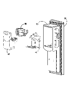
As shown in FIG. 3, the exemplary ice making, storage and dispensing
compartment 30 is
disposed on the interior of left side fresh food compartment door 32. An
apparatus 40 for
breaking ice clumps can be mounted into the compartment 30. A driving assembly
41,
also disposed within the compartment 30, is drivingly engageable with the
apparatus 40.
For example, the driving assembly 41 has a motor for rotatably driving the
apparatus 40.
An electronic ice maker 38 can he disposed above the apparatus 40. The
apparatus 40
can be removed and replaced into the ice making, storage and dispensing
compartment 30
by a user for cleaning or other purposes.
As shown in FIG. 4, the exemplary apparatus 40 includes an ice storage bin 42,
an axle
44 rotatably supported by the ice storage bin 42, an actuator 45 (shown in
FIGs. 6-7C)
operatively coupled to the axle 44 to rotate upon the driving of the axle 44,
and an ice
breaker 46 operatively coupled to the actuator 45 and disposed within the ice
storage bin
42. The ice breaker 46 is configured to move in a reciprocal manner upon
rotation of the
actuator 45, to break ice clumps formed by the ice cubes in the ice storage
bin 42.
The apparatus 40 further includes a housing 60 disposed within the ice storage
bin 42.
The housing 60 includes a front wall 56, a first opening 66 in the front wall
56, and a
second opening (not shown) downstream of the first opening 66 such that ice
can move
from the first opening 66 to the second opening under gravity or action. Ice
cubes of
CA 02753951 2011-09-29
241679
suitable sizes can pass through the first opening 66 ad move into an ice
crushing area
within the housing 60, where the ice cubes can be crushed or shaved by a set
of blades
driven by the axle 44, under a user's input. The second opening is in
communication
with the outlet 53 of the compartment 30 to allow the crushed or shaved ice be
dispensed
through the outlet 53.
As illustrated in FIG. 5, the apparatus 40 can further include an agitator 48
disposed
within the storage bin 42 substantially opposite to the first opening 66 of
the housing 60.
The agitator 48 is operatively coupled to the axle 44 and configured to rotate
upon
driving of the axle 44. For example, the agitator 48 can include at least one
extension 49a
with curved profile, for propelling ice cubes present in the ice storage bin
42 into the
housing 60 through the first opening 66.
Ice cubes stored in the storage bin 42 may clump together if exposed
repeatedly to
warming and freezing cycles. In this case, the ice clumps formed from the ice
cubes may
stick to the ice storage bin 42 and/or become too big to enter the first
opening 66. Thus,
no ice can be delivered under a user's input. The ice breaker 46, according to
the
exemplary embodiment of the present invention, serves to break the ice clumps
into ice
pieces sufficiently small to pass through the first opening 66.
As shown in FIG. 5, the apparatus 40 further includes structures for
mechanically
engaging the driving assembly 41. For example, the apparatus 40 includes a
pair of
mating tabs 58a and 58b and a coupler 74, disposed externally of the ice
storage bin 42.
The mating tabs 58a and 58b are configured to releasably engage complementary
mating
structures of the driving assembly 41, which will be described later. The
coupler 74 is
secured to the axle 42 and configured to transfer the rotation of a motor of
the driving
assembly 41 to the axle 44 of the apparatus 40. For example, the coupler 74
can have
two extensions 80 and 81 extending away from the surface of the coupler 74,
which are
configured to engage complementary structures of the motor so as to transfer
the rotation
of the motor to the axle 44.
6
CA 02753951 2011-09-29
241679
FIG. 6 is a partial perspective view showing the apparatus 40 having the ice
breaker 46
for breaking ice clumps. The ice breaker 46 is operatively coupled to the
actuator 45. In
the shown embodiment, the actuator 45 includes an eccentric cam affixed to the
axle 44,
so that as the axle 44 rotates in either direction, the off-center placement
of the eccentric
cam causes the ice breaker 46 to move reciprocally. As the axle 44 rotates,
the ice
breaker 46, with its reciprocal movement, exerts a force on clumps of ice
which are
present in the ice storage bin 42.
In this exemplary embodiment, the ice breaker 46 is disposed adjacent to the
front wall
56 of the housing 60, and includes an elongated body 110 having a first end
112 and a
second end 114 connected by a middle portion 116. The first end 112 is
operatively
connected to the actuator 45, and the second end 114 is disposed to extend
beyond the
housing 60. Optionally, the ice breaker 46 may further include a tip 118
extending
angularly from the second end 114 and preferably above the housing 60. For
example,
the tip 118 of ice breaker 46 is shown as taking a 90 angle from the
elongated body 110
of the ice breaker 46, but the tip 118 could be arranged in any suitable
direction. The tip
118 is provided to enhance the ice breaking ability of the ice breaker 46.
However, a
person of ordinary skill in the art understands that any part of the ice
breaker 46 can break
clumps of ice present in the ice storage bin 42.
The apparatus 40 further includes an ice breaker guide 47a for guiding the ice
breaker
46's movement. For example, the ice breaker guide 47a, in cooperation with the
actuator
45 such as the eccentric cam, guides ice breaker 46 to move reciprocally in a
desirable
manner. FIGs. 7A-7C illustrates three exemplary embodiments of how the ice
breaker 46
is guided and operated.
As shown in FIG. 7A, the ice breaker 46 includes a cavity 113, for example, a
substantially rectangular cavity, disposed in the first end 112 of the
elongated body 110.
The eccentric cam 45 is operatively accommodated in the cavity 113. The ice
breaker
guide 47a is in the form of a band straddling over the middle portion 116 of
the elongated
body 110, so that the ice breaker 46 can translates upwardly and downwardly in
a
7
CA 02753951 2011-09-29
241679
reciprocal manner under the guidance of the guide 47a, as represented by
exemplary
directional arrow 51. However, a person of ordinary skill in the art
understands that the
ice breaker guide 47a can also include other configurations for guiding the
reciprocal
translation of the ice breaker 46 along other directions.
FIG. 7B shows another exemplary embodiment of the ice breaker guide,
identified by
numeral reference 47b. The guide 47b is in the form of a pin fixed to the
front wall 56 of
the housing 60. The pin 47b extends through the middle portion 116 of the
elongated
body 117, to allow the second end 114 to pivot reciprocally upon rotation of
the eccentric
cam 45, along the direction represented by exemplary directional arrow 52.
FIG. 7C shows another exemplary embodiment of the ice breaker guide,
identified by
numeral reference 47c. The guide 47c is in the form of a pair of brackets
secured to the
front wall 56 of the housing 60. The brackets 47c are disposed at either side
of the
middle portion 116 of the elongated body 110, respectively. In this
embodiment, the ice
breaker 46 includes a cavity 115, provided in the first end 112 of the
elongated body 110,
which has an inner profile substantially complementary to the outer profile of
the
eccentric cam 45. When the eccentric cam 45 rotates under the driving of the
axle 44, the
pair of brackets 47c cooperatively engage the middle portion 116 of the ice
breaker 46, to
allow the second end 114 of the ice breaker 46 to move in a substantially
circular fashion,
as represented by exemplary directional arrow 54.
If large clumps of ice are formed within the ice storage bin 42, clumps which
may be too
large to fit through the first housing opening 66 or too large to be dispensed
to a user,
typically stop all flow of ice. Referring again to FIG. 4, when a user inputs
a stimulus
requesting ice, the axle 44 rotates and facilitates the movement of whole ice
cubes within
the ice storage bin 42, through the first housing opening 66 and into a user's
receptacle.
At the same time, the ice breaker 46 also is moved as the axle 44 rotates as
described in
the examples above and shown in FIGs. 7A-7C. As the ice breaker 46 is moved,
it
contacts clumps of ice and breaks up the clumps of ice to a sufficiently small
size, so that
8
CA 02753951 2011-09-29
241679
the broken clumps of ice can pass through the first housing opening 66 and can
be
dispensed to a user.
The driving assembly 41 drives the ice breaker 46 as well as the set of blades
in the ice
crushing area of the housing 60. As shown in FIG. 8A, the driving assembly 41
includes
a base member 43 and a motor 69 which can be mounted to the base member 43.
The
motor 69 includes a motor axle 65 extending from the motor 69 and through an
opening
of the base member 43. The driving assembly 41 further includes a motor fork
70, which
is disposes on the opposite side of the base member 43, with respect to the
motor 69. The
motor fork 70 is fixedly secured to the motor axle 65 through a securer 67. In
this
embodiment, the motor securer 67 is shown as a threaded nut but could be any
means for
securing motor fork 70 to motor axle 65. The motor fork 70 is configured to
engage the
coupler 74 of the apparatus 40, thereby transferring the drive torque of the
motor axle 65
to the axle 44 of the apparatus 40. The motor fork 70 can include a pair of
extensions 82
and 83, which engage the pair of extensions 80 and 81 (shown in FIG. 5) of the
coupler
74, respectively. The driving assembly 41 further includes a pair of mating
latches 59a
and 59b, which are configured to releasably engage the mating tabs 58a and 58b
(shown
in FIG. 5) of the apparatus 40.
During operation, the driving assembly 41 is first installed in the
compartment 30, for
example, on the interior of left side fresh food compartment door 32.
Subsequently, the
apparatus 40 is mechanically attached to the driving assembly 41 through the
engagement
between the mating tabs 58a and 58b of the apparatus 40 and the mating latches
59a and
59b of the driving assembly 41. At the same time, the apparatus 40 is drivenly
connected
to the driving assembly 41 through the engagement between the extensions 80
and 81 of
the coupler 74 and the extensions 82 and 83 of the motor fork 70. Once the
apparatus 40
and the driving assembly 41 are mechanically and operatively connected to each
other,
sealing material can be applied to place them in the compartment 30 in a
sealed manner.
FIG. 9 shows the process for attaching the ice clumps breaking apparatus 40 to
the
driving assembly 41 and removing the apparatus 40 from the driving assembly
41. As
9
CA 02753951 2011-09-29
241679
shown, for a user to attach the apparatus 40, the user slides the ice storage
bin 42 into the
compartment 30 and vertically down so that the tabs 58a and 58b catch the
latches 59a
and 59b respectively. The movement to attach the apparatus 40 is represented
by an ice
storage bin insertion arrow 72. For a user to remove the apparatus 40, the
user lifts the
ice storage bin 42 vertically upwards, and subsequently slides the ice storage
bin 42 out
of the compartment 30 so that the tabs 58a and 58b move above the edge of the
tab
latches 59a and 59b. The movement to remove the apparatus 40 is represented by
an ice
storage bin removal arrow 71.
Attachment and removal of the apparatus 40 with respect to the driving
assembly 41 can
occur, as long as the coupler 74 of the apparatus 40 and the motor fork 70 of
the driving
assembly 41 are properly aligned to each other. FIGs. 10A and lOB are views of
the
interaction between the coupler 74 of the apparatus 40 and motor fork 70 of
the driving
assembly 41 as viewed from the motor 69, looking at the exterior of the ice
storage bin
42. FIGs. IOA and I OB show the interaction of ice storage bin coupler 74 and
motor fork
70, such that they contact each other upon rotation.
The motor fork extensions 82 and 83 of the motor fork 70 interact with the
extensions 80
and 81 of the coupler 74 respectively, so that when the motor 69 rotates,
motor fork
extensions 82 and 83 contact and cause the coupler extensions 80 and 81 to
rotate
accordingly.
In the orientation shown in FIG. 1OA, if a user were to remove ice storage bin
42, the
coupler 74 could vertically pass the motor fork 70, as shown by an exemplary
removal
direction arrow 75, without either of the sections of the coupler 74 and motor
fork 70
getting stuck and/or obstructing each other. In the orientation shown in FIG.
IOB, if a
user were to attempt to remove the ice storage bin 42, in. the direction of
the exemplary
removal direction arrow 75, the motor fork extension 82 would interfere the
coupler
extension 80, preventing the removal of ice storage bin 42.
During operation, the coupler 74 and the motor fork 70 may end their rotation
at any
orientation in reference to each other, depending on the random time a user
causes the
CA 02753951 2011-09-29
241679
motor 69 to stop rotating. The orientations shown in FIGs. 10A and l0B are two
examples of the orientation of the coupler 74 and the motor fork 70 after they
stop
rotating. The motor 69 can cause the coupler 74 and the motor fork 70 to
rotate in either
a clockwise or counter-clockwise direction based on an input by a user.
According to another exemplary aspect of the present invention, a method of
operating a
refrigerator is provided. The exemplary method ensures that the removal of the
ice
storage bin 40 can occur by ensuring that the extensions 80 and 81 of the ice
storage bin
coupler 74 and the extensions 82 and 83 of the motor fork 70 do not stop
rotation at an
orientation where the extensions would interfere with each other, such as the
one shown
in FIG. I OB.
The exemplary method includes engaging the motor fork 70 of the driving
assembly 41
of the refrigerator with the coupler 74 of the ice clumps breaking apparatus
40 of the
refrigerator; rotating the motor fork 70 in a first direction based on a
user's input; and
rotating the motor fork 70 in a second direction, opposite to the first
direction, for a
predetermined time or by a predetermined angle after at the end of the user's
input.
FIG. 11 is a graphical representation of the coupler 74, the coupler
extensions 80 and 81,
the motor fork 70, and the motor fork extensions 82 and 83. In this graphical
representation, the coupler extensions 80 and 81 would be extending out of the
page
towards the motor fork 70 while the motor fork extensions 82 and 83 would be
extending
into the page, towards the coupler 74. The motor fork 70 rotates in either
direction, based
on input by a user. For example, if a user wants whole ice cubes, the motor
fork 70
rotates in a first, clockwise direction, and if a user wants shaved or crushed
ice cubes, the
motor fork 70 rotates in a second, counter-clockwise direction.
In order to ensure that the extensions of the coupler 74 and the motor fork 70
do not stop
rotation vertically above each other and removal of the ice storage bin 42 can
be
achieved, the motor 69 rotates in a direction opposite to the direction it was
rotating to
dispense ice for a predetermined time or by a predetermined angle.
11
CA 02753951 2011-09-29
241679
For example, if the motor fork 70 stops rotation in position 90, as shown by
the solid
lines in FIG. 11, and the motor fork 70 has been rotating in a clockwise
direction, the
motor 69 will rotate the motor fork 70 in a second, counter-clockwise
direction for a
predetermined time or by a predetermined angle so that the motor fork will
rest in
position 91, as shown by the dashed lines in FIG. 11. In another example, if
the motor
fork 70 is being rotated in a counter-clockwise direction to dispense ice, the
motor 69 will
rotate the motor fork 70 in the clockwise direction for a predetermined time
or by a
predetermined angle after the user ends his or her input to dispense ice.
The predetermined time or angle is sufficient to provide a clearance between
the coupler
extensions 80 and 81 and the motor fork extensions 82 and 83, so as to allow
the ice
storage bin 42 to be lifted along the removal direction arrow 75 shown in FIG.
10A. The
predetermined time or angle would be set to allow the motor fork 70 to rotate
counter
wise so that it would not contact the coupler extensions 80, 81. As shown in
FIG. 11, the
motor fork 70 extends substantially along a first axis I-I and the coupler 74
extends
substantially alone a second axis II-II. For example, the predetermined time
or angle can
be set to allow the motor fork 70 to rotate counter wise so that the first
axis I-I of the
motor fork 70 and the second axis II-II of the coupler 74 would form an angle
in the
range between 45 and 135 . Preferably, the motor fork 70 rotates counter wise
to allow
the first axis I-I and the second axis II-II to be substantially perpendicular
to each other.
In this way, at the end of the rotation, the motor fork 70 would be halfway to
contacting
the opposite coupler extensions 80, 81. In the example shown in FIG. 11, at
the end of
rotation to dispense ice, the motor fork extension 83 is contacting the
coupler extension
80. The motor fork 70 would then rotate in the counter-clockwise direction to
position
91, which would be roughly halfway to the position where the motor fork
extension 83
contacts the coupler extension 81. This method ensures that whichever
orientation the
motor fork 70 and the coupler 74 obtain after rotation to dispense ice, the
extensions of
the motor fork 70 and the coupler 74 will not block the removal of the ice
storage bin 42.
In the exemplary embodiment shown in FIG. 11, the rotational radius R1 of the
motor
fork 70 is 0.75", and the angle a between the a first prong 85 and a second
prong 87 of
12
CA 02753951 2011-09-29
241679
the extension 80 or 81 of the coupler 74 is about 88 . Furthermore, the motor
fork 70 and
the coupler 74 are dimensioned so that, when the motor fork 70 rotates halfway
between
the extensions 80 and 81 of the coupler 74 to allow the first axis I-I to be
substantially
perpendicular to the second axis II-II, a clearance of 0.25" is provided
between the motor
fork 70 and the coupler 74, which is sufficient to lift the ice storage bin 42
along the
removal direction arrow 75 shown in FIG. 10A to remove the ice storage bin 42.
Accordingly, in this exemplary embodiment, a predetermined angle 0 for
rotating the
motor fork 70 counter clockwise can be determined by the following equation:
(3=(90 - a
/2). Thus, the predetermined angle (3 is about 46 , so that the first axis I-I
and the second
axis 11-II would be substantially perpendicular to each other to place the
motor fork 70
halfway to contacting the opposite coupler extensions 80, 81. Since the motor
69 rotates
25 RPM at no load, a predetermined time for rotating the motor fork 70 can be
about 0.31
seconds. In another embodiment, the predetermined angle 0 is in the range from
16 to
76 .
However, a person of ordinary skill in the art understands that the
predetermined time or
angle for rotating the motor fork changes as the angle a and/or the rotating
speed of the
motor change. In addition, the necessary clearance for lifting the ice storage
bin 42
changes as the dimensions of the motor fork and the coupler change.
Accordingly,
without departing from the spirit of the above aspect of the present
invention, the person
is able to make necessary adjustments to the predetermined time or angle
considering the
above factors, to ensure that the coupler and the motor fork do not interfere
with each
other.
FIG. 12 is a block diagram of an exemplary ice dispenser control system 100.
The ice
dispenser control system 100 includes the motor 69, a controller 102 and a
user stimulus
101. The method of controlling the motor 69 based on the user stimulus 101 is
inputted
into the controller 102, for example, by programming into memory of an
application
specific integrated circuit (ASIC) or other programmable memory device. Both
predetermined time and angle, which the motor 69 rotates in the direction
opposite to the
direction it was rotating to dispense ice, can be programmed into the
controller 102.
13
CA 02753951 2011-09-29
241679
The controller 102 controls the operation of the motor 69 based on the user
stimulus 101.
If a user stimulus 101 occurs, causing the motor 69 to rotate either clockwise
or counter-
clockwise, the controller 102 will then cause the motor 69 to rotate in the
opposite
direction for a predetermined time or angle after the user stimulus 101 ends.
This
predetermined time or angle can be programmed into the memory of the
controller 102.
An ice dispenser assembly is provided which provides for the dispensing of ice
and the
removal of an ice storage bin in an efficient and reliable manner. Ice
dispensing
efficiency is increased through the breaking of ice clumps by the ice breaker.
Ice storage
bin removal is also enhanced and provides a method which ensures that removal
can
occur easily and the ice storage bin coupler and motor fork will not hinder
removal of the
ice storage bin.
The fundamental novel features of the invention as applied to various specific
embodiments thereof have been shown, described and pointed out, it will also
be
understood that various omissions, substitutions and changes in the form and
details of
the devices illustrated and in their operation, may be made by those skilled
in the art
without departing from the spirit of the invention. For example, it is
expressly intended
that all combinations of those elements and/or method steps which perform
substantially
the same function in substantially the same way to achieve the same results
are within the
scope of the invention. Moreover, it should be recognized that structures
and/or elements
and/or method steps shown and/or described in connection with any disclosed
form or
embodiment of the invention may be incorporated in any other disclosed or
described or
suggested form or embodiment as a general matter of design choice. It is the
intention,
therefore, to be limited only as indicated by the scope of the claims appended
hereto.
14