Language selection

Search

Patent 2753983 Summary

Third-party information liability

Some of the information on this Web page has been provided by external sources. The Government of Canada is not responsible for the accuracy, reliability or currency of the information supplied by external sources. Users wishing to rely upon this information should consult directly with the source of the information. Content provided by external sources is not subject to official languages, privacy and accessibility requirements.

Claims and Abstract availability

Any discrepancies in the text and image of the Claims and Abstract are due to differing posting times. Text of the Claims and Abstract are posted:

  • At the time the application is open to public inspection;
  • At the time of issue of the patent (grant).
(12) Patent: (11) CA 2753983
(54) English Title: FIBER MANAGEMENT SPOOL
(54) French Title: BOBINE DE GESTION DE FIBRES
Status: Granted
Bibliographic Data
(51) International Patent Classification (IPC):
  • B65H 75/18 (2006.01)
  • B65H 49/36 (2006.01)
  • B65H 75/12 (2006.01)
(72) Inventors :
  • KIMBRELL, EDDIE (United States of America)
  • COURCHAINE, WILFRED (United States of America)
(73) Owners :
  • AFL TELECOMMUNICATIONS LLC (United States of America)
(71) Applicants :
  • AFL TELECOMMUNICATIONS LLC (United States of America)
(74) Agent: SMART & BIGGAR LP
(74) Associate agent:
(45) Issued: 2017-05-23
(86) PCT Filing Date: 2010-09-14
(87) Open to Public Inspection: 2011-03-17
Examination requested: 2015-06-29
Availability of licence: N/A
(25) Language of filing: English

Patent Cooperation Treaty (PCT): Yes
(86) PCT Filing Number: PCT/US2010/048690
(87) International Publication Number: WO2011/032118
(85) National Entry: 2011-08-30

(30) Application Priority Data:
Application No. Country/Territory Date
61/242,001 United States of America 2009-09-14

Abstracts

English Abstract


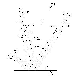
Provided is a fiber management spool, the
spool including a barrel extending up from a bottom portion.
The spool further includes at least one outer fiber retaining
arm extending up from an annular portion of the
bottom portion and the annular portion extends radially
away from an outer circumferential surface of the barrel.
The at least one snap finger extends downward from a
central portion of the bottom portion, wherein the snap
finger is configured to engage a panel to releasably secure
the spool to the panel.


French Abstract

La présente invention se rapporte à une bobine de gestion de fibres, la bobine comprenant un cylindre s'étendant vers le haut depuis une partie inférieure. La bobine comprend en outre au moins un bras extérieur de retenue de fibres s'étendant vers le haut depuis une partie annulaire de la partie inférieure et la partie annulaire s'étend radialement en s'éloignant d'une surface circonférentielle extérieure du cylindre. La ou les doigts d'encliquetage s'étendent vers le bas depuis une partie centrale de la partie inférieure, les doigts d'encliquetage étant conçus pour mettre en prise un panneau afin de fixer de manière amovible la bobine au panneau.

Claims

Note: Claims are shown in the official language in which they were submitted.


What is claimed is:

1. A fiber management spool, the spool comprising:
a barrel extending up from a bottom portion;
a plurality of outer fiber retaining arms extending up from an annular portion
of the
bottom portion, the annular portion extending radially away from an outer
circumferential
surface of the barrel; and
a plurality of snap fingers extending downward from a central portion of the
bottom
portion; and
an extension member that extends upward from each of the snap fingers, the
extension member configured as a lever that moves an engaging part of the snap
finger,
wherein the snap fingers are configured to flex when engaging complementary
recessions in a panel to releasably secure the spool to the panel.
2. The fiber management spool according to claim 1, further comprising:
a plurality of tab members disposed on a top portion of the barrel that are
configured
to releasably couple with a second fiber management spool.
3. The fiber management spool according to claim 2, further comprising:
a plurality of openings in the bottom portion each configured to receive a tab
member
from another spool.
4. The fiber management spool according to claim 2, further comprising:
a plurality of inner retaining arms extending radially from the top of the
barrel.

9

5. The fiber management spool according to claim 4, further comprising:
an alignment member configured to engage with the second fiber management
spool
when the second fiber management spool is coupled to the spool.
6. The fiber management spool according to claim 4, further comprising:
inward extensions at a top of the outer retaining arms,
wherein the inward extensions are disposed closer to the annular portion.
7. A fiber management system, the system comprising:
a panel;
a spool that comprises:
a barrel extending up from a bottom portion;
a plurality of fiber retaining arms extending up from an annular portion of
the
bottom portion, the annular portion extending radially away from an outer
circumferential surface of the barrel;
a plurality of snap fingers extending downward from a central portion of the
bottom portion; and
an extension member that extends upward from each of the snap fingers, the
extension member configured as a lever that moves an engaging part of the snap

finger;
wherein the snap fingers are configured to flex when engaging complementary
recessions in the panel to releasably secure the spool to the panel.


8. The fiber management system according to claim 7, further comprising:
a plurality of tab members disposed on a top portion of the barrel that are
configured
to releasably couple with a second fiber management spool disposed on a side
of the spool
that is distant from the panel.
9. The fiber management system according to claim 8, further comprising:
a plurality of openings in the bottom portion each configured to receive a tab
member
from another spool.
10. The fiber management system according to claim 8, further comprising:
a plurality of barrel arms extending radially from the top of the barrel.
11. The fiber management system according to claim 10, further comprising:
an alignment member configured to engage with the second fiber management
spool
when the second fiber management spool is coupled to the spool.
12. The fiber management system according to claim 10, wherein the spool
includes a recessed portion in bottom portion that corresponds to a raised
portion in the
panel.
13. A method for managing optical fibers, the method comprising:
attaching the spool of claim 1 to a panel using the snap fingers; and
wrapping an optical fiber around the barrel.

11

14. The method according to claim 13, wherein the spool is attached to the
panel
before the optical fiber is wrapped around the barrel.
15. The method according to claim 13, wherein the spool is attached to the
panel
after the optical fiber is wrapped around the barrel.
16. A fiber management spool, the spool comprising:
a barrel extending up from a bottom portion;
at least one outer fiber retaining arm extending up from an annular portion of
the
bottom portion, the annular portion extending radially away from an outer
circumferential
surface of the barrel;
at least one snap finger extending downward from a central portion of the
bottom
portion; and
an extension member that extends upward from each of the snap fingers, the
extension member configured as a lever that moves an engaging part of the snap
finger;
wherein the snap finger is configured to flex when engaging a complementary
recession in a panel to releasably secure the spool to the panel.
12

Description

Note: Descriptions are shown in the official language in which they were submitted.


CA 02753983 2016-12-01
FIBER MANAGEMENT SPOOL
BACKGROUND OF THE INVENTION
1. Field of the Invention
[02] Methods and apparatuses consistent with aspects of the present
invention
relate to a fiber management system including a spool for holding fiber optic
cables and a
panel for securing the spool.
2. Background of the Invention
[03] Panels, shelves, enclosures commonly use spools to store and control
the bend
radius of optical fibers and optical fiber cables to prevent attenuation due
to excessive
bending. In the related art, spools are attached using screws, PEM studs, etc.
To be
connected in this fashion requires additional hardware which adds to the cost
and usage
limitations of existing panels, shelves, etc. Thus, there is a need for a
spool apparatus that
does not require additional hardware to be secured to a panel.

CA 02753983 2011-08-30
WO 2011/032118
PCT/US2010/048690
SUMMARY OF THE INVENTION
[04] An aspect of the invention is to provide a fiber management
system including a fiber management spool and a panel for securing the same.
[05] In accordance with an aspect of the present invention, a fiber
management spool is provided and includes a barrel extending up from a bottom
portion and a plurality of fiber retaining arms extending up from an annular
portion of the bottom portion, the annular portion extending radially away
from
an outer circumferential surface of the barrel. The spool also includes a
plurality
of snap fingers extending downward from a central portion of the bottom
portion
that are configured to engage a panel to releasably secure the spool to the
panel.
The spool may also include a plurality of barrel arms extending radially from
the
top of the barrel.
[06] The fiber management spool may also include an extension
member that extends upward from each of the snap fingers; the extension member

is configured as a lever that moves an engaging part of the snap finger. A
plurality of tab members may be disposed on a top portion of the barrel and
are
configured to releasably couple with a second fiber management spool to enable

the stacking of multiple spools. A plurality of openings may also be formed in
the
bottom portion of the spool and configured to receive a tab member from
another
spool.
2

CA 02753983 2011-08-30
WO 2011/032118
PCT/US2010/048690
[07] According to another aspect, the spool may also include an
alignment member configured to engage with a second fiber management spool
when the second fiber management spool is coupled to the spool.
[08] According to another aspect, a fiber management system is
provided. The system includes a panel configured to receive a spool.
The spool includes a barrel extending up from a bottom portion and a plurality
of
fiber retaining arms extending up from an annular portion of the bottom
portion,
the annular portion extending radially away from an outer circumferential
surface
of the barrel. The spool also includes a plurality of snap fingers extending
downward from a central portion of the bottom portion that are configured to
engage a panel to releasably secure the spool to the panel. The spool may also

include a plurality of barrel arms extending radially from the top of the
barrel.
[09] According to another aspect, the system may also include an
extension member that extends upward from each of the snap fingers, the
extension member is configured as a lever that moves an engaging part of the
snap finger to release the snap finger from engagement with the panel. The
spool
may include a plurality of tab members disposed on a top portion of the
cylindrical barrel that are configured to releasably couple with a second
fiber
management spool disposed on a side of the spool that is distant from the
panel.
[10] According to another aspect, the spool includes a recessed portion
in bottom portion that corresponds to a raised portion in the panel.
3

CA 02753983 2011-08-30
WO 2011/032118
PCT/US2010/048690
[11] According to another aspect, a method is provided wherein the
spool is attached to a panel using the snap fingers and an optical fiber is
wrapped
around the barrel of the spool. The optical fiber may be wrapped around the
spool
either before or after the spool is attached to the panel.
BRIEF DESCRIPTION OF THE DRAWINGS
[12] The above and/or other aspects of the invention will become
apparent and more readily appreciated from the following description of the
exemplary embodiments, taken in conjunction with the accompanying drawings
in which:
[13] FIG. 1 is a perspective view showing a spool according to a first
exemplary embodiment;
[14] FIG. 2 is a perspective view showing stacked spools;
[15] FIG. 3 is a perspective view showing the bottom of the spool
according to the first exemplary embodiment;
[16] FIG. 4 is a perspective view showing a spool according to a second
exemplary embodiment;
[17] FIG. 5 is a cross-sectional view showing a spool according to the
second embodiment;
[18] FIG. 6 is a perspective view showing a panel configured to secure
a spool of either the first or second embodiments.
DETAILED DESCRIPTION OF THE EXEMPLARY EMBODIMENTS
4

CA 02753983 2011-08-30
WO 2011/032118
PCT/US2010/048690
[19] Hereinafter the non-limiting exemplary embodiments of the
present invention will be described in detail with reference to the
accompanying
drawings.
[20] The first exemplary embodiment is shown in FIGS. 1-3. FIG. 1
shows a spool 10 configured to hold and retain fiber optic cables. The spool
10
includes various components for holding a fiber optic cable. Specifically, the

spool 10 includes a cylindrical shaped barrel 20 extending away from a bottom
portion 30. Inner fiber retaining arms 140 extend radially outward from the
top of
the barrel 20. The spool 10 also includes an annular portion 150 that is
provided
around the periphery of the bottom of the barrel 20. A plurality of outer
fiber
retaining arms 140 extend upward from an outer peripheral portion of the
annular
portion 150. These outer fiber retaining arms 140 include inward extensions
160
that are provided at a top of each outer fiber retaining arm 140. The inward
extensions 160 extend inward toward the barrel 20. Further, as shown in FIG.
1,
to facilitate the installation or removal of fiber optic cables from the spool
10, the
inner fiber retaining arms 40 and the outer fiber retaining arms 140 are
alternately
disposed around the circumference of the spool 10. The barrel 20, the inner
retaining arms 40 and the outer retaining arms 140 define the optical fiber
storage
= area of the spool 10.
[21] The spool 10 also includes snap fingers 50 that are configured
to
releasably attach the spool 10 to a panel 180. The spool 10 may also include a

CA 02753983 2011-08-30
WO 2011/032118
PCT/US2010/048690
center hole 120 for securing the spool 10 to a panel 180 using a screw, bolt,
etc.
As shown in FIGS. 1, 3 and 5, the snap fingers 50 have a U-shape so that the
snap
fingers may flex when inserted into a receiving hole, such as snap finger
receiving
portions 160 shown in FIG. 6. An engaging part 90 of the snap finger 50 is
configured to releasably secure the spool 10 to a panel 180. Panel as used
herein
includes, but is not limited to a flat panel. A panel refers to any structure
upon
which the spool 10 may be mounted, e.g., a shelf, wall, curved surface, etc.
[22] Additionally, to facilitate the alignment and attachment to a panel
180, the spool 10 may also include a recessed portion 60 that is configured to

mate with a raised portion 170 on a panel 180. Further, the spool 10 may also
include pins 110 disposed on the lower side of the bottom portion 30. These
pins
30 are configured to engage with corresponding alignment holes 100 on a panel
180.
[23] As shown in FIG. 2, the spool 10 may be configured so as to
releasably engage another spool 10 to form a spool stack. To enable this
stacking,
the spool 10 includes tabs 70 disposed on an upper portion that are configured
to
engage tab receiving portions 80 (openings) disposed on a lower portion of
another spool 10. In the embodiment depicted in FIG. 1, the tabs 70 are
disposed
on an upper portion of the barrel 20 and extend upward from the bottom portion

30 and inward toward a center of the spool 10. The tab receiving portions 80
are
6

CA 02753983 2011-08-30
WO 2011/032118
PCT/US2010/048690
disposed on a bottom portion 30 of the spool 10 at a position inside of the
barrel
20.
[24] Further, to aid in alignment of the stacked spool configuration, the
alignment holes 100 may be included on an upper surface of the spool 10 so as
to
engage with pins 110 disposed on the bottom surface of another spool 10. In
the
embodiment of FIG. 1, these alignment holes 100 are provided on the inner
fiber
retaining arms 40. However, the present invention is not limited to this
configuration and the alignment hole may be placed on any portion of the upper

surface of the spool 10.
[25] Also, the inner and outer fiber retaining arms 40, 140 may be set at
a different height. In particular, as shown in FIG. 2, the height of the
extensions
160 is set lower than the inner fiber retaining arms 40 so that the optical
fiber may
be placed on the lower of the stacked spools 10 after the upper spool 10 is
placed
on the lower spool.
[26] A second embodiment of the present invention is shown in FIGS. 4
and 5, and may include any of the features described above with respect to the

first embodiment. In this embodiment, the snap fingers 50 of the spool 10
further
include extensions 130 that extend upward from the snap fingers 50. These
extensions 130 are configured to function as a level to aid in securing and
releasing the snap fingers 50 from a panel 180. In this particular
configuration,
the extensions 130 are provided on snap fingers 50 disposed on opposite sides
of
7

CA 02753983 2011-08-30
WO 2011/032118
PCT/US2010/048690
the center of the spool 10 such that they can be pressed toward one another to

release or secure the spool 10 to a panel 180.
[27] A fiber management system is provided by using the spool 10 of
either the first or second embodiment in combination with the panel of FIG. 6.

The panel 180 may be a wall mountable device or may comprise an internal
component or external wall of a fiber optic cabinet.
[28] The spool 10 may be utilized according to the following method.
Spools 10 may be fitted with fiber optic cable before being attached to a
panel
180. When additional fiber optic cables are required, additional spools may be

added by merely attaching a spool directly to a panel 180, or by stacking an
additional spool 10 onto an already attached spool 10.
[29] Although a few exemplary embodiments of the present invention
have been shown and described, it would be appreciated by those skilled in the
art
that changes may be made in this embodiment without departing from the
principles and spirit of the invention, the scope of which is defined in the
claims
and their equivalents. Additionally, while the spools are described above for
use
with fiber optic cables, the invention is not so limited. Rather, the spools
may be
used with wires or any other type of flexible cable.
8

Representative Drawing
A single figure which represents the drawing illustrating the invention.
Administrative Status

For a clearer understanding of the status of the application/patent presented on this page, the site Disclaimer , as well as the definitions for Patent , Administrative Status , Maintenance Fee  and Payment History  should be consulted.

Administrative Status

Title Date
Forecasted Issue Date 2017-05-23
(86) PCT Filing Date 2010-09-14
(87) PCT Publication Date 2011-03-17
(85) National Entry 2011-08-30
Examination Requested 2015-06-29
(45) Issued 2017-05-23

Abandonment History

There is no abandonment history.

Maintenance Fee

Last Payment of $263.14 was received on 2023-09-08


 Upcoming maintenance fee amounts

Description Date Amount
Next Payment if small entity fee 2024-09-16 $125.00
Next Payment if standard fee 2024-09-16 $347.00

Note : If the full payment has not been received on or before the date indicated, a further fee may be required which may be one of the following

  • the reinstatement fee;
  • the late payment fee; or
  • additional fee to reverse deemed expiry.

Patent fees are adjusted on the 1st of January every year. The amounts above are the current amounts if received by December 31 of the current year.
Please refer to the CIPO Patent Fees web page to see all current fee amounts.

Payment History

Fee Type Anniversary Year Due Date Amount Paid Paid Date
Registration of a document - section 124 $100.00 2011-08-30
Application Fee $400.00 2011-08-30
Maintenance Fee - Application - New Act 2 2012-09-14 $100.00 2012-08-20
Maintenance Fee - Application - New Act 3 2013-09-16 $100.00 2013-08-20
Maintenance Fee - Application - New Act 4 2014-09-15 $100.00 2014-08-20
Request for Examination $800.00 2015-06-29
Maintenance Fee - Application - New Act 5 2015-09-14 $200.00 2015-08-20
Maintenance Fee - Application - New Act 6 2016-09-14 $200.00 2016-08-19
Final Fee $300.00 2017-04-04
Maintenance Fee - Patent - New Act 7 2017-09-14 $200.00 2017-09-11
Maintenance Fee - Patent - New Act 8 2018-09-14 $200.00 2018-09-10
Maintenance Fee - Patent - New Act 9 2019-09-16 $200.00 2019-09-06
Maintenance Fee - Patent - New Act 10 2020-09-14 $250.00 2020-09-04
Maintenance Fee - Patent - New Act 11 2021-09-14 $255.00 2021-09-10
Maintenance Fee - Patent - New Act 12 2022-09-14 $254.49 2022-09-09
Maintenance Fee - Patent - New Act 13 2023-09-14 $263.14 2023-09-08
Owners on Record

Note: Records showing the ownership history in alphabetical order.

Current Owners on Record
AFL TELECOMMUNICATIONS LLC
Past Owners on Record
None
Past Owners that do not appear in the "Owners on Record" listing will appear in other documentation within the application.
Documents

To view selected files, please enter reCAPTCHA code :


To view images, click a link in the Document Description column. To download the documents, select one or more checkboxes in the first column and then click the "Download Selected in PDF format (Zip Archive)" or the "Download Selected as Single PDF" button.

List of published and non-published patent-specific documents on the CPD .

If you have any difficulty accessing content, you can call the Client Service Centre at 1-866-997-1936 or send them an e-mail at CIPO Client Service Centre.


Document
Description 
Date
(yyyy-mm-dd) 
Number of pages   Size of Image (KB) 
Abstract 2011-08-30 2 69
Claims 2011-08-30 6 120
Drawings 2011-08-30 6 137
Description 2011-08-30 8 278
Representative Drawing 2011-10-25 1 15
Cover Page 2011-10-25 1 43
Description 2016-12-01 8 267
Claims 2016-12-01 4 96
PCT 2011-08-30 2 71
Assignment 2011-08-30 8 218
Request for Examination 2015-06-29 1 33
Examiner Requisition 2016-06-02 4 287
Amendment 2016-12-01 10 255
Final Fee 2017-04-04 1 48
Representative Drawing 2017-04-24 1 8
Cover Page 2017-04-24 1 48