Note: Descriptions are shown in the official language in which they were submitted.
CA 02754074 2011-08-31
WO 2010/125555 PCT/IL2010/000296
-1-
CUTTING TOOL AND A PROCESS FOR MAKING SUCH A CUTTING
TOOL
FIELD OF THE INVENTION
The present invention relates to the field of cutting tools that are made
by a continuous and uninterrupted injection and extrusion process, and more
specifically, to the field of drills that are made by such an injection and
extrusion
process.
BACKGROUND OF THE INVENTION
The use of an extrusion process for the production of cutting tools made
of cemented carbide is known. There are several types of cutting tools that
may be
produced by such a process, e.g., drills, end mills, reamers, taps, as well as
countersinking and counterboring tools. The required cutting tool may be
extruded
to the desired diameter and length, and then, the necessary chip evacuation
flutes
are produced.
In some cases, the chip evacuation flutes may be parallel to a longitudinal
axis
of the cutting tool, as required, for example, in some kinds of reamers. In
other
cases, the chip evacuation flutes may extend spirally around the longitudinal
axis,
as required, for example, in other kinds of reamers, and in end mills and
drills.
Each of the cutting tools may be provided with a cooling channel that extends
from its rear portion to its front portion in order to supply cooling liquid
to the
CA 02754074 2011-08-31
WO 2010/125555 PCT/IL2010/000296
-2-
cutting area. When the cutting tool is provided with helical chip evacuation
flutes
then, typically, also the cooling channels extend spirally around the
longitudinal
axis, following the helix of the flutes.
Each of the above described cutting tools comprises a shank portion, in a rear
portion thereof, and, a fluted portion extending forwardly from the shank
portion.
The shank portion is typically in the form of a round rod and serves for
holding the
cutting tool by a cutting machine or by an adapter.
There are known various methods for the production of the helical flutes and
for the production of the spiral cooling channels.
US Pat. No. 6,669,414 to Puide teaches how to manufacture a helix drill by
extruding a blank and then sintering the blank. During the extrusion, a
mixture is
passed through a die which provides a cylindrical shape to the outer
peripheral
surface of the mixture. A plurality of jaws are disposed downstream of the die
for
conducting the mixture. Each jaw includes a helical ridge for engaging the
outer
surface of the extruded material to cause a helical groove to be formed
therein
which constitutes a chip flute in the tool. During the extrusion, the jaws are
moved
away from the mixture to terminate formation of the chip groove, whereby a
shank
portion of the tool is formed. In order to transfer flushing medium from the
spindle
to the tip of the drill, two flush channels extend through the entire drill.
A disadvantage of such a construction is the difficulty of connecting the
coolant supply to the thin flush channels. Furthermore, the massive
construction of
the shank portion encounters an unnecessary waste of cemented carbide.
Another method for producing a drill blank is disclosed in US 7,296,497 to
Kugelberg et al. The method comprising extruding a first blank portion (B 1)
having a free end and external flutes, allowing the extrusion to continue to
supply
further extruding mass into a cavity (6), the supply completely fills out the
external
flutes of the first blank portion (B 1) to produce a second blank portion (B2)
integral
with the first blank portion (B I), allowing the extrusion to continue to
produce a
CA 02754074 2011-08-31
WO 2010/125555 PCT/IL2010/000296
-3-
desired length of the first blank portion (B 1), and cutting off the first
blank portion
(B 1) at the end facing away from the second blank portion (B2).
Such a method suffers from the same disadvantages as described above.
Another method for producing a drill blank is disclosed in US 7,340,978 to
Kugelberg et al. The method comprising extruding a mixture in a feed direction
by
means of a die to form the diameter of the mixture body. The mixture body
passes
against a chisel which forms a chip flute in the outer periphery of the
mixture body
by chip-removing machining. When the chisel is displaced away from the mixture
body, a non-fluted shaft portion is formed. By rotating the mixture body while
contacted by the chisel, a helical chip flute can be formed. Alternatively,
the body
could be twisted after a straight flute has been formed, whereupon the flute
becomes helical.
Also in this case, the method suffers from the same disadvantages as
described above.
In some cases, it is beneficial to produce a cutting tool from regions having
a
different structure. Regions having different structures means that they
differ by
their qualities, for example, one region, typically a peripheral one, may be
more
wear resistant, whilst another region, typically an inner one, may be tougher
and
less brittle.
The properties of the cemented carbide materials are determined by, for
example, the chemical composition of the ceramic component, the particle size
of
the ceramic component, the chemical composition of the binder, and the ratio
of
binder to ceramic component. The different characteristics of the different
regions
may be differences in; modulus of elasticity, hardness, wear resistance,
fracture
toughness, tensile strength, corrosion resistance, coefficient of thermal
expansion,
and coefficient of thermal conductivity.
Methods for producing cutting tools having regions of a different structure
are
known in the art. Such methods are disclosed, for example, in US 6,511,265 to
CA 02754074 2011-08-31
WO 2010/125555 PCT/IL2010/000296
-4-
Mirchandani et al., in US 6,450,739 to Puide et al. and in US 6,274,082 to
Nagahora et al. However, in a co-extrusion method, which is a composite
technique for a molten metal material, an entire surface of a first material
is
covered with a second material. Thus, even unnecessary parts are covered, and
the
characteristics of the first material cannot sufficiently be exhibited. This
may be
disadvantageous from the standpoint of costs.
It is the object of the present invention to provide a cutting tool and a
process
for making such a cutting tool that reduces or overcomes the aforementioned
disadvantages.
It is a further object of the present invention to provide a cutting tool that
is
made by a continuous and uninterrupted injection and extrusion process.
It is still a further object of the present invention to provide a drill that
is made
by such a combined injection and extrusion process.
It is yet a further object of the present invention to provide a cutting tool
and a
process for making such a cutting tool, wherein the cutting tool is provided
with
cooling channels in the fluted portion thereof and with a large cooling bore
and an
economical shank construction in the shank portion thereof.
It is still yet a further object of the present invention to provide a cutting
tool
and a process for making such a cutting tool, wherein the cutting tool is made
of
regions having a different structure, and the inner material is only partially
covered
by the outer material.
SUMMARY OF THE INVENTION
In accordance with the present invention there is provided a cutting tool
comprising:
an injection molded shank, and
an extruded fluted portion extending from the injection molded shank,
wherein the injection molded shank and the extruded fluted portion have a
monolithic construction.
CA 02754074 2011-08-31
WO 2010/125555 PCT/IL2010/000296
-5-
In accordance with preferred embodiments, the shank comprises a bore
extending forwardly from a rear end of the shank.
In accordance with some embodiments, the bore is cylindrical and
symmetrical with respect to a longitudinal axis of the cutting tool.
In accordance with other embodiments, the bore has a non-round cross-
section taken in a plane perpendicular to a longitudinal axis of the cutting
tool.
In accordance with some embodiments, the shank has a shank diameter D3;
the bore has a bore diameter D4; and
a diameter ratio E between the bore diameter D4 and the shank diameter D3 is
in
the range of 0.6 to 0.9.
If desired, the fluted portion comprises at least one internal cooling channel
that extends forwardly from a front end of the bore.
In some embodiments, the bore is straight; and
at least one internal cooling channel extends forwardly from a front end of
the bore.
In some embodiments, the bore is twisted; and
at least one twisted cooling channel extends forwardly from a front end of the
bore.
In some embodiments, the fluted portion comprises at least one internal
cooling channel having a non-round cross-section taken in a plane
perpendicular to
a longitudinal axis C of the cutting tool.
Advantageously, the fluted portion comprises at least one flute peripheral
portion having a flute leading edge at a leading end of the flute peripheral
portion,
and a flute trailing edge at a trailing end of the flute peripheral portion;
and
the fluted portion comprises at least one internal cooling channel that is
closer to
the flute leading edge than to the flute trailing edge, as seen in a cross-
section taken
in a plane perpendicular to a longitudinal axis C of the cutting tool.
Further advantageously, the fluted portion comprises at least one flute
peripheral portion having a flute leading edge at a leading end of the flute
peripheral portion, and a flute trailing edge at a trailing end of the flute
peripheral
portion; and
the tool material of the fluted portion adjacent the flute peripheral portion
has
CA 02754074 2011-08-31
WO 2010/125555 PCT/IL2010/000296
-6-
different properties with respect to the tool material of the fluted portion
remote
from the flute peripheral portion.
Still further advantageously, the fluted portion comprises at least one flute
peripheral portion having a flute leading edge, at a leading end of the flute
peripheral portion, and, a flute trailing edge, at a trailing end of the flute
peripheral
portion; and
the tool material of the fluted portion adjacent the flute leading edge has
different
properties with respect to the tool material of the fluted portion remote from
the
flute leading edge.
If desired, the shank is made of a first material having first material
properties; and
at least a portion of the fluted portion is made of a second material having
second
material properties that differ from the first material properties.
In some embodiments, the fluted portion comprises a cutting head; and
at least the cutting head is made of the second material.
In some embodiments, at least a portion of a length of the fluted portion is
made of a harder material than a remaining portion of the length of the fluted
portion.
If desired, the shank has a shank diameter D3;
the fluted portion has a fluted portion diameter D5; and
the shank diameter D3 differs from the fluted portion diameter D5.
In some embodiments, the cutting tool comprises a cutting portion in a front
portion of the cutting tool; and
the cutting portion extends radially outwardly from the fluted portion.
There is also provided in accordance with the present invention a process for
making a cutting tool having a shank and a fluted portion comprising the steps
of:
forming a cutting tool green body by:
injection molding a shank of the green body; and
extruding a fluted portion of the green body such that the shank
and the fluted portion have a monolithic construction; and
CA 02754074 2011-08-31
WO 2010/125555 PCT/IL2010/000296
-7-
sintering the green body.
The process may include:
prior to forming the cutting tool body, providing an injection and extrusion
system (10) comprising:
a fixed portion; and
a movable portion that contacts the fixed portion and is capable of
moving away from the fixed portion along a bidirectional movement
direction; wherein:
one of the fixed and movable portions comprises a die
having a die bore with a longitudinal axis, the die bore facing
along the movement direction; and
the other of the fixed and movable portions comprises a
cavity insert having a longitudinal axis and an insert bore that
faces the die bore;
and wherein:
forming the cutting tool green body comprises:
(i) injecting molten tool material through the die bore and into the insert
bore, thus forming a shank of the cutting tool green body;
(ii) moving the movable portion away from the fixed portion, and,
simultaneously, extruding molten tool material through the die bore, thus
forming a desired length of a fluted portion of the cutting tool green body,
such that the shank and the fluted portion have a monolithic construction; and
(iii) cutting the fluted portion by a blade.
The blade may cut in a direction perpendicular to the movement direction.
The process may comprise the further step of ejecting the shank from the
insert bore prior to sintering the cutting tool green body.
Typically, the insert bore comprises a core that extends rearwardly from an
insert bore bottom.
Generally, the core has a core diameter D 1;
the insert bore has a cavity diameter D2; and
CA 02754074 2011-08-31
WO 2010/125555 PCT/IL2010/000296
-8-
a diameter ratio E between the core diameter D 1 and the cavity diameter D2 is
in
the range of 0.6 to 0.9.
In some embodiments, the die bore comprises die bore portions that are
twisted along the die bore; and
the cavity insert is rotatable around its longitudinal axis B, with respect to
whichever of the fixed portion and the movable portion it belongs.
If desired, the cavity insert is forcibly rotatable.
In some embodiments, the die bore comprises at least one pin that extends
rearwardly from a forward portion of the die bore.
If desired, the at least one pin is twisted at least along a front portion
thereof.
Advantageously, a cross-section of the at least one pin, taken in a plane
perpendicular to the longitudinal axis A of the die bore, is not round.
In some embodiments, the die bore comprises a die bore peripheral portion
associated with the at least one pin;
the. die bore peripheral portion merges with a first die bore convex portion
at a first
bore edge and with a second die bore convex portion at a second bore edge; and
the at least one pin is closer to the first bore edge than to the second bore
edge.
Advantageously, the die bore comprises a die bore peripheral portion
associated with the at least one pin;
the die bore peripheral portion merges with a first die bore convex portion at
a first
bore edge and with a second die bore convex portion at a second bore edge;
a first chamber is defined between the die bore peripheral portion and a
separation
plate;
a second chamber is defined between the separation plate and the longitudinal
axis
A of the die bore; and
the first chamber is connected to an intake of a first tool material and the
second
chamber is connected to an intake of a second tool material.
If desired, the first tool material is different from the second tool
material.
Further if desired, the first tool material is harder than the second tool
material; and
CA 02754074 2011-08-31
WO 2010/125555 PCT/IL2010/000296
-9-
the second tool material is tougher than the first tool material.
In some embodiments, at least a portion of a length of the fluted portion is
made from the first tool material and a remaining portion of the length of the
fluted
portion is made from the second tool material.
Advantageously, the separation plate is connected to the at least one pin.
In some embodiments, the first chamber comprises the first bore edge and the
second bore edge.
In some embodiments, the first chamber comprises the first bore edge; and
the second chamber comprises the second bore edge.
If desired, the first chamber comprises the at least one pin.
Further if desired, the second chamber comprises the at least one pin.
Typically, the insert bore has a cavity bore diameter D2;
the die bore has a die bore diameter D6; and
the cavity bore diameter D2 equals the die bore diameter D6.
In some embodiments, the insert bore has a cavity bore diameter D2;
the die bore has a die bore diameter D6; and
the cavity bore diameter D2 differs from the die bore diameter D6.
In some embodiments, the fixed portion comprises the die and the movable
portion comprises the cavity insert. In other embodiments, the fixed portion
comprises the cavity insert and the movable portion comprises the die.
There is also provided in accordance with the present invention a process for
making a cutting tool green body having a shank and a fluted portion
comprising
the steps of:
injection molding a shank of the green body; and
extruding a fluted portion of the green body such that the shank and the
fluted
portion have a monolithic construction.
BRIEF DESCRIPTION OF THE DRAWINGS
For a better understanding of the present invention and to show how the same
may be carried out in practice, reference will now be made to the accompanying
CA 02754074 2011-08-31
WO 2010/125555 PCT/IL2010/000296
-10-
drawings, in which:
Fig. 1 is a schematical cross-sectional view of an injection and extruding
system in accordance with the present invention during the injection process;
Fig. 2 is a schematical cross-sectional view of an injection and extruding
system in accordance with the present invention during the extrusion process;
Fig. 3 is a schematical cross-sectional view of an injection and extruding
system in accordance with the present invention during the injection process
of
producing a cutting tool having cooling channels and a shank bore;
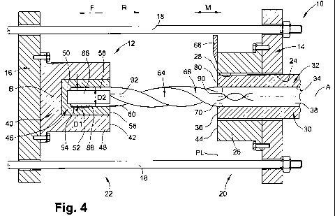
Fig. 4 is a schematical cross-sectional view of an injection and extruding
system in accordance with the present invention during the extrusion process
of
producing a cutting tool having cooling channels and a shank bore;
Fig. 5 is a side view of a cutting tool produced by the injection and
extrusion
system according to the present invention;
Fig. 6 is a longitudinal cross-section of the cutting tool of Fig. 5;
Fig. 7 is a cross-sectional view of a die according to the present invention
that
enables forming a cutting tool having different material properties adjacent a
flute
peripheral portion;
Fig. 8 is a cross-sectional view of a die according to the present invention
that
enables forming a cutting tool having different material properties adjacent a
leading edge of a flute peripheral portion;
Fig. 9 is a cross-sectional view of a die having a non-round pin;
Fig. 10 is a cross-sectional view of a die having a pin that is not
symmetrical
with respect to the die bore convex portions; and
Fig. 11 is a cross-sectional view of the cutting tool taken along line XI-XI
in
Fig. 5.
DETAILED DESCRIPTION OF THE INVENTION
Attention is first drawn to Fig. 1, showing an injection and extruding system
10 in accordance with the present invention. The injection and extruding
system 10
(hereinafter referred to as the "system") comprises basic components of an
injection
CA 02754074 2011-08-31
WO 2010/125555 PCT/IL2010/000296
-11-
machine 12 as known in the art. However, the system 10 provides a process of
manufacturing a product that combines both an injection molding process and an
extrusion process as will be later described. For the sake of clarity, it
should be
understood that the term an "injection machine" is also known as an "injection
molding machine" where molten material is injected into a cavity of a mold.
The system 10 comprises a fixed plate 14 that is connected to a movable plate
16 by means of tie bars 18. Typically, the system 10 comprises four tie bars
18 that
are parallel to each other and enable sliding of the movable plate 16 along a
bidirectional movement direction M that is perpendicular to the fixed plate
14.
The system 10 is not limited to comprise four tie bars 18 and other numbers
of tie bars may be used. Thus, in some embodiments, the system 10 may comprise
two tie bars. Furthermore, according to other embodiments, the injection
machine
12 may operate in a different manner, and, without tie bars.
The fixed plate 14 serves as a base for various parts that form a fixed
portion
of the system 10. Likewise, the movable plate 16 serves as a base for various
parts that form a movable portion 22 of the system 10. When the movable
portion
22 joins the fixed portion 20, they join at a parting line PL. The parting
line PL
lies in a plane that is perpendicular to the movement direction M. The
direction
20 from the fixed plate 14 toward the movable plate 16 forms a forward
direction F of
the system 10, wherein an opposite direction forms a rearward direction R of
the
system 10.
The fixed plate 14 is provided with a centrally located fixed plate bore 24. A
mold fixed portion 26, forming a part of the fixed portion 20, is connected to
the
fixed plate 14 and extends forwardly therefrom. The mold fixed portion 26 is
provided with a centrally located fixed mold bore 28 that extends coaxially
with the
fixed plate bore 24.
A die 30 is located, and may have a sliding contact, within the fixed mold
bore 28 and the fixed plate bore 24. The die 30 has a die body 32 and a
centrally
CA 02754074 2011-08-31
WO 2010/125555 PCT/IL2010/000296
-12-
located die bore 34, having a longitudinal axis A, that extends rearwardly
from a
die front end 36. The die 30 extends from the die front end 36, that reaches
the
parting line PL, and rearwardly beyond the fixed plate 14. It is understood by
a
person skilled in the art that, when the injection machine 12 comprises an
injection
unit having a cylinder (not shown), the die 30 may be connected to the
cylinder of
the injection unit of the injection machine 12. Alternatively, the die 30 may
form a
part of the mold fixed portion 26.
The die 30 is provided with a plurality of heating elements (not shown). The
heating elements may be located within the die body 32 or outwardly therefrom.
The heating elements heat tool material 38 located in the die bore 34 up to an
extrusion temperature T1.
According to the present invention, the tool material 38 comprises cemented
carbides with the addition of a binder as known in the art. However, the
present
invention is not limited to the use of cemented carbides only and other tool
materials may be used for producing cutting tools. Such materials may be, for
example, ceramic, steel, HSS or the like.
As is known to those skilled in the art, the tool material may be feeded into
a
hopper (not shown) and pressed towards the die bore 34 by means of a single or
twin screw auger (not shown), powered by an electric or hydraulic motor (not
shown), or a ram (not shown), driven by hydraulic pressure or electrical
means.
A mold moving portion 40, forming a part of the movable portion 22, is
connected to the movable plate 16 and extends rearwardly therefrom. At the
position shown in Fig. 1, the mold moving portion 40 extends rearwardly up to
the
parting line PL and a moving portion rear end 42 abuts the die front end 36
and a
fixed mold front end 44 of the mold fixed portion 26.
A cavity insert 46, having a longitudinal axis B, is located in a moving
portion
rear section 48 of the mold moving portion 40. The cavity insert 46 has an
insert
body 50 and a centrally located insert bore 52 having an insert bore bottom
54. The
CA 02754074 2011-08-31
WO 2010/125555 PCT/IL2010/000296
-13-
insert bore 52 extends rearwardly from the insert bore bottom 54 and opens to
an
insert rear face 56 that, at the position shown in Fig. 1, abuts the die front
end 36 at
the parting line PL. The longitudinal axis B of the cavity insert 46 is
coaxial with
the longitudinal axis A of the die bore 34. The cavity insert 46 is held at a
cavity
temperature T2 and it serves as a mold 58 into which the shank 60 of the
cutting
tool 62, having a longitudinal axis C, is injected and formed.
The cavity insert 46 is rotatable with respect to the mold moving portion 40
around the longitudinal axis B of the cavity insert 46. The cavity insert 46
may be
freely rotated, or, forcibly rotated by means of an electric motor, hydraulic
motor,
and the like (not shown in the figures).
In one embodiment, a continuous and uninterrupted process for making a
cutting tool according to the present invention involves both an injection
stage and
an extrusion stage. The process for making a cutting tool may comprise the
following steps:
At the first step, molten tool material 38 is injected through the die 30 and
into the cavity insert 46 in an injection process (sometimes referred to as
"injection
molding") as known in the art. At this stage, as shown in Fig. 1, the mold
moving
portion 40 is forcibly held against the die 30 and the mold fixed portion 26
along
the parting line PL. The cavity insert 46 is maintained at the cavity
temperature T2
that is lower than the extrusion temperature T1 by which the tool material 38
is
held within the die bore 34.
The molten tool material 38, being pressed with high pressure and
temperature, fills the insert bore 52 and thus is formed in the shape of the
desired
shank 60 of the cutting tool 62. At this stage, the shank 60 cools down to the
cavity
temperature T2 and starts to solidify wherein the system 10 is ready for the
next
step, namely, the extrusion of the fluted portion 64.
At this stage, as shown in Fig. 2, two simultaneous actions take place. First,
CA 02754074 2011-08-31
WO 2010/125555 PCT/IL2010/000296
-14-
the movable plate 16 is moved forwardly so that the movable portion 22 is
separated from the fixed portion 20 at the parting line PL and away from the
die
30. Second, molten tool material 38 is extruded through the die 30.
When a desired length L of the fluted portion 64 has been reached, the
extrusion of the molten tool material 38 through the die 30 is stopped, the
forward
movement of the movable plate 16 is stopped, and a blade 66 cuts the green
body
68 of the cutting tool 62 along the parting line PL, in a direction
perpendicular to
the longitudinal axis A of the die bore 34.
In accordance with some embodiments, the fluted portion 64 may be straight.
In accordance with other embodiments, the fluted portion 64 may be twisted as
shown in Fig. 2.
When straight flutes are required, the die bore 34 has the shape of the cross
section of the fluted portion 64, at least along a forward portion 70 of the
die bore
34. This shape may be constant along a given length of the die bore 34.
When twisted flutes are required, as shown for example in Fig. 2, the die bore
34 has the shape of the cross section of the fluted portion. This shape is
twisted
along a given length of the die bore 34, at least along a forward portion 70
of the
die bore 34.
Thus, in the example shown in Fig. 2, the fluted portion 64 is extruded from
the die 30 in a twisted manner. The movable portion 22 is moved forwardly at a
speed that corresponds to the rate of extrusion of the molten tool material 38
through the die 30.
Since the fluted portion is extruded in a twisted manner, the shank 60 also
has
to be rotated in order not to break the green body 68 of the cutting tool 62.
Therefore, the cavity insert 46 may be freely rotated, or, it may be
constrained to
rotate at the desired speed by means of an electric motor, hydraulic means, or
the
like.
Clearly, if the cutting tool 62 is produced with straight flutes, then, the
shank
60 does not have to be rotated with the fluted portion, and, therefore, also
the cavity
CA 02754074 2011-08-31
WO 2010/125555 PCT/IL2010/000296
-15-
insert 46 does not have to be rotated with respect to the mold moving portion
40.
At the final step of the process for the production of a green body, the green
body 68 of the cutting tool 62 is ejected from the cavity insert 46, and, the
movable
portion 22 is moved rearwardly to lie against the fixed portion 20 to be ready
for
the next cycle of injection and extrusion for producing another green body 68
of a
cutting tool 62.
As a final production stage of the cutting tool 62, the green body 68 may be
sintered and the final shape and size of the shank 60, the fluted portion 64,
and a
cutting head 72 in a front portion 74 of the cutting tool 62 may be produced
by, for
example, a grinding process.
Thus, the resulting cutting tool 62 comprises an injection molded shank 60
and an extruded fluted portion 64 having a monolithic construction, the term
"monolithic" referring to the fact that the shank and the fluted portion of
the cutting
tool have unitary, one-piece construction and were not formed as discrete
members
which later were joined together. Similarly, in the green body, the shank and
the
fluted portion also have a monolithic construction, the green body being
formed as
one piece in a single continuous and uninterrupted production process.
Throughout the specification and claims reference is made to the phrase
"sintering" with regard to the green body. However, it is understood by a
person
skilled in the art that the process of forming a green body, which is
typically soft
and brittle, into a solid hard body may comprise other stages like, for
example,
chemical debinding and thermal debinding.
In the described embodiment, reference is made to directions as "forwardly"
and "rearwardly" which relate to a process that takes place in a horizontal
direction.
However, the process for making a cutting tool according to the present
invention
is not limited to a horizontal direction only and other spatial directions may
be
chosen. For example, the injection and extrusion may take place in a vertical
direction, i.e., in a direction that is perpendicular to ground.
CA 02754074 2011-08-31
WO 2010/125555 PCT/IL2010/000296
-16-
Furthermore, care must be taken with regards to the forward and rear
directions as defined for the process (Figs. 1 to 4) which are oppositely
defined
with relation to the cutting tool (Figs. 5 and 6). Hence, in the injection and
extrusion system 10, the cavity insert 46, for producing the shank 60, is
located
forwardly to the die 30, for producing the fluted portion 64, whereas, at the
cutting
tool 62, the fluted portion 64 extends forwardly from the shank 60.
After the injection of the shank 60, the fluted portion 64 may be extruded to
any desired length and is limited, practically, only by the length of the
machine,
namely, the length in which the movable portion 22 can be distanced from the
fixed
portion 20.
The die 30 is formed in a shape that corresponds to the shape of a cross-
section of the fluted portion 64 of the cutting tool 62. The size of the
fluted portion
64 of the green body, as obtained through the extrusion, is such that after
sintering
of the green body, it may be similar to the final size of the fluted portion
64 of the
cutting tool 62, or, if desired, slightly larger therefrom in order to enable
grinding
of the flutes 76 to the exact desired shape and size. Thus, by having the
flutes 76
made in, or almost in, their final shape and size after the sintering stage, a
considerable amount of time and money is saved by this process.
The process for making a cutting tool as described above may be
implemented to cutting tools having straight flutes, for example, some kinds
of
reamers or deep hole drills, or, to cutting tools having twisted flutes, like
drills and
end mills.
In some cases, when the cutting tool 62 has to be provided with internal
cooling channels 78 (see Figs. 5 and 6), the die 30 is further provided with
pins 80
that extend along the die bore 34 and rearwardly from the forward portion 70
thereof (see Figs. 3 and 4). The pins 80 are fixed within the die bore 34 and
reach
the parting line PL.
CA 02754074 2011-08-31
WO 2010/125555 PCT/IL2010/000296
-17-
If the cooling channels are to be straight, then, the pins 80 are also
straight. If
the cooling channels are to be helically twisted, then, a front portion of the
pins 80
is also helically twisted within the die bore 34, as shown in Fig. 3. The pins
80 are
connected to the die body 32, typically at a rear portion of the pins 80, by
methods
known in the art.
In a case when it is desired to produce a shank 60 having a bore 82 that opens
to a rear end 84 of the shank 60, then, the cavity insert 46 is further
provided with a
suitable core 86 that is connected to the insert bore bottom 54.
An advantage of an injection and extrusion process according to the present
invention may be particularly implemented when it is desired to form an
economical shank construction that may have a large bore 82 at its rear end 84
thus
saving a substantial amount of tool material 38. The large bore 82 may be used
also for the passage of a cooling medium therethrough toward the cutting
portion
124 of the cutting tool 62, by means of internal cooling channels 78 that
extend
forwardly from a front end 112 of the bore 82. A further advantage of the
large
bore 82 arises from the fact that the connection therewith with the cooling
medium
supply becomes much easier instead of having to connect the cooling supply to
much thinner internal cooling channels 78.
In such a case, when the cavity insert 46 is provided with a core 86 (see
Figs.
3 and 4), the core 86 extends rearwardly from the insert bore bottom 54. The
core
has a core diameter D1 that is smaller than a cavity diameter D2 of the cavity
insert
46. Thus, during the injection process, the tool material 38 fills the space
between
the core 86, the walls 88 of the cavity insert 46 and the insert bore bottom
54.
In this manner, and advantageously over the prior art, the shank 60 is formed,
wherein in this case the shank 60 has a large bore 82 and a relatively thin
wall
thickness L1. The green body of the shank 60 has a shank diameter D3, and, the
CA 02754074 2011-08-31
WO 2010/125555 PCT/IL2010/000296
-18-
bore 82 has a bore diameter D4. The shank diameter D3 may be equal to the
cavity
diameter D2, and, the bore diameter D4 may be equal to the core diameter D1.
The
meaning of the term "large" with respect to the bore 82 means that a diameter
ratio
E between the bore diameter D4 and the shank diameter D3 is relatively large.
Typically, the diameter ratio E may be in the range of 0.6 to 0.9. For
example, a
drill having a shank diameter D3 of 3 mm may be provided with a bore 82 having
a
bore diameter D4 of 2 mm, whereas, a drill having a shank diameter D3 of 20 mm
may be provided with a bore 82 having a bore diameter D4 of 16 or 18 mm,
corresponding to a wall thickness L1 of 2 mm or 1 mm.
The diameter ratio E is not defined with respect to the cutting tool only and
it
may be equally defined with respect to the cavity insert. Hence, the diameter
ratio
E is also the ratio between the core diameter DI and the cavity diameter D2.
Despite the above examples, it is understood that a cutting tool or a process
for making such a cutting tool according to the present invention is not
limited to
the dimensions described above and other dimensions may be chosen. For
example, the shank diameter D3 of the cutting tool may be also smaller than 3
mm
or larger than 20 mm. Furthermore, the diameter ratio E is not limited to the
range
of 0.6 to 0.9, and higher or lower ratios may be chosen.
The large bore 82 introduces several advantages. First, it enables much easier
connection of a cooling supply at the rear end 84 of the shank 60. Second, it
enables to save a large amount of cemented carbide, and hence, money, compared
to prior art cutting tools. Furthermore, these advantages are obtained through
a
continuous and uninterrupted process without necessity of further production
processing, such as, for example, wire cutting of the cemented carbide in
order to
produce a large bore at the rear end of the shank.
In embodiments in which the fluted portion 64 is provided with an internal
cooling channel or channels 78, the die 30 is provided, as described above,
with a
pin or pins 80 that extend rearwardly from the forward portion 70 of the die
bore
CA 02754074 2011-08-31
WO 2010/125555 PCT/IL2010/000296
-19-
34. In such embodiments, in the first step of the process, when the movable
plate
16 is forcibly held against the fixed plate 14 along the parting line PL, a
forward
end 90 of the pin or pins 80 is held in contact with a rear end 92 of the core
86.
This is done in order to ensure that at the end of the injection and extrusion
process
a continuous path for a cooling medium is formed from the rear end 84 of the
shank
60 to a front portion 74 of the cutting tool 62 (see Fig. 5).
In the embodiment shown in Figs. 5 and 6, the shank 60 of the cutting tool 62
has a shank diameter D3 and the fluted portion 64 has a fluted portion
diameter D5,
that is slightly smaller than the shank diameter D3. However, the fluted
portion
diameter D5 does not have to be smaller than the shank diameter D3 and it may
be
equal to, or larger than, the shank diameter D3.
When it is desired to produce the shank diameter D3 larger than the fluted
portion diameter D5, then, the cavity diameter D2 is larger than a die bore
diameter
D6. Alternatively, when it is desired to produce the shank diameter D3 smaller
than the fluted portion diameter D5, then, the cavity diameter D2 is smaller
than the
die bore diameter D6.
The injection and extrusion process according to the present invention may be
particularly useful for the production of cemented carbide drills having,
typically
two, helical flutes 76, and internal cooling channels 78. In such a case, the
die will
be provided with two spiral pins 80. However, according to the present
invention,
the cutting tools produced according to the injection and extrusion process
may
equally have other number of helical flutes, for example, three or four, by
changing
the cross-section of the die bore 34. In such a case, if the cutting tool is
provided
with internal cooling channels that correspond to the number of the flutes,
then, the
die is provided with pins in a number that corresponds to the number of the
internal
cooling channels.
CA 02754074 2011-08-31
WO 2010/125555 PCT/IL2010/000296
-20-
The process for making a cutting tool according to the present invention may
be beneficial when it is required to make the cutting tool with regions having
a
different structure. Specifically, the present invention teaches how to make a
cutting tool with two different regions, wherein an inner region is only
partially
covered by an outer region.
Fig. 7 shows a cross-section of one embodiment of a die 30 according to the
present invention. The die 30 comprises a die bore 34 formed within a die body
32.
Two pins 80 extend along the die bore 34 up to a forward portion 70 of the die
bore
34.
The die 30 may be used for making a twist drill 94 having internal cooling
channels 78, as shown in Fig. 5. The die bore 34 has two opposed die bore
peripheral portions 96, and two die bore convex portions 98 therebetween.
Clearly,
the shape of the die bore 34 corresponds to the shape of the cutting tool 62
being
produced, and the present invention is not limited to the shape described
herein.
Thus, for example, there may be any number of die bore peripheral portions and
die
bore convex portions, for example, one, three, or more. The number of the
internal
cooling channels may be equal to the number of the die bore peripheral
portions, or,
may differ therefrom. The die bore convex portions may have a different shape
rather than convex.
Separation plates 100 extend between each of the pins 80 to the die bore
convex portions 98. The separation plates 100 extend from a rear portion of
the
pins 80 and they may extend up to the forward portion 70 of the die bore 34.
However, the separation plates 100 do not have to extend up to the forward
portion
70 of the die bore 34, and they may end at a point that is rearward to the
forward
portion 70 of the die bore 34. The separation plates 100 generally follow the
path
of the pins 80, namely, if the pins 80 extend linearly, then, also the
separation plates
100 extend linearly, whereas, if the pins 80 extend spirally, then, also the
separation
plates 100 extend spirally.
CA 02754074 2011-08-31
WO 2010/125555 PCT/IL2010/000296
-21-
The connection between the pins 80 and the separation plates 100 adds
rigidity to the pins 80 and increases the accuracy of their position, and
thereby also
increases the accuracy of the cooling channels 78 and of the entire cutting
tool 72
produced according to the present invention. The separation plates 100 do not
have
to be connected to the center of the pins 80 as shown in Fig. 7. Thus, in some
embodiments, the separation plates 100 are connected at the side of the pins
80 that
are closest to the longitudinal axis A of the die bore 34. In other
embodiments, the
separation plates 100 are connected at the side of the pins 80 that are remote
from
the longitudinal axis A of the die bore 34.
Furthermore, the separation plates 100 do not have to be connected to the pins
80. Thus, in some embodiments, each of the separation plates 100 is located
between a pin 80 and the longitudinal axis A of the die bore 34. In other
embodiments, each of the pins 80 is located between a separation plate 100 and
the
longitudinal axis A of the die bore 34.
During the extrusion stage, two different mixtures are inserted into the die
bore 34. A first mixture is inserted into a first chamber 102 formed between
each
of the separation plates 100 and a corresponding die bore peripheral portion
96. A
second mixture is inserted into a second chamber 104 formed between the
separation plates 100.
When the two different mixtures are extruded beyond the die front end 36,
they merge with each other, forming a green body having different properties
at
different portions thereof. Typically, the mixture at the first chamber 102 is
harder
and more wear-resistant than the mixture at the second chamber 104, wherein
the
mixture at the second chamber 104 is typically tougher than the mixture at the
first
chamber 102. Thus, advantageously, a cutting tool can be formed, having
different
properties at different portions thereof, wherein the inner material is only
partially
covered by the outer material.
According to one embodiment of the present invention, during the injection
CA 02754074 2011-08-31
WO 2010/125555 PCT/IL2010/000296
-22-
stage, only the second mixture found at the second chamber 104 is injected
into the
mold 58. Then, during the extrusion stage, the two mixtures are co-extruded,
thus
forming a fluted portion 64 having different properties at different portions
thereof.
Thus, a major portion of the cutting tool 62, including the shank 60, is
formed from
a tough material, and, the cutting portion of the cutting tool 62, at regions
remote
from the longitudinal axis C of the cutting tool 62, is formed from a hard and
wear-
resistant material.
In some embodiments, it is required that only a portion of the cutting tool 62
in the vicinity of a land 106 be formed from a hard and wear-resistant
material. In
a case of an end mill, for example, this requirement applies to the vicinity
of the
cutting edge that extends spirally rearwardly from the front portion 74 of the
cutting
tool 62.
In such case, as shown in Fig. 8, each of the separation plates 100 extends
from a die bore peripheral portion 96 to one adjacent die bore convex portion
98
thus forming an enclosed first chamber 102 in the vicinity of only one bore
edge
108 of the die bore 34 that is formed between a die bore peripheral portion 96
and a
die bore convex portion 98.
Thus, when a cutting tool 62 is produced by means of the die 30 shown in
Fig. 8, the hard and wear-resistant material extruded through the first
chamber 102
makes the cutting edge and its vicinity harder than the rest portions of the
cutting
tool 62. As can be further seen in Fig. 8, the pins 80 are not located
symmetrically
with respect to the die bore convex portions 98, rather, they are located
closer to the
bore edge 108 that corresponds to a cutting edge of the cutting tool. In this
manner,
it is guaranteed that the internal cooling channel 78 will be closer to the
cutting
edge, thus more efficiently cooling the cutting zone that comes in contact
with the
workpiece during machining. This results in easier cutting, better cooling,
prolonged tool life and more economical cooling process.
CA 02754074 2011-08-31
WO 2010/125555 PCT/IL2010/000296
-23-
In some embodiments, as shown for example in Fig. 9, the pin 80 does not
have a circular cross-section as shown in Figs. 7 and 8. Rather, the pin 30
has a
cross-section having border lines 110 that are generally parallel to the
adjacent
walls of the die bore 34, i.e., to a given die bore peripheral portion 96 and
to the die
bore convex portions 98.
Such a construction of the pin 80 enables the internal cooling channel to be
formed such that the cooling is evenly spread along the periphery of the
cutting tool
thus making the cooling more efficient and the tool's life may be prolonged.
Fig. 10 shows another embodiment wherein the pin 80 is not symmetrical
with respect to the die bore convex portions 98. In this case, the pin 80 is
located
closer to a bore edge 108. As a consequence, as shown in Fig. 11, the cutting
tool
62 will have internal cooling channels 78 that are closer to a flute leading
edge 114
of a flute peripheral portion 116 than to a flute trailing edge 118 of the
flute
peripheral portion 116, as seen in a cross-section taken in a plane
perpendicular to
the longitudinal axis C of the cutting tool. The flute leading edge 114 is
formed,
with respect to a direction of rotation G, at a leading end 120 of the flute
peripheral
portion 116, at the intersection of the flute peripheral portion 116 with a
flute 76.
The flute trailing edge 118 is formed at a trailing end 122 of the flute
peripheral
portion 116, at the intersection of the flute peripheral portion 116 with an
opposite
flute 76.
Thus, the cooling agent that will flow in the internal cooling channel of the
cutting tool will be in the region of the cutting edge where most of the heat
is
generated. In this manner, the cooling will be more efficient and economical
since
cooling of unnecessary portions of the cutting tool will be advantageously
prevented. Thus, while prolonging the tool's life, cooling expenses can be
reduced.
Although the present invention has been described to a certain degree of
particularity, it should be understood that various alterations and
modifications
CA 02754074 2011-08-31
WO 2010/125555 PCT/IL2010/000296
-24-
could be made without departing from the spirit or scope of the invention as
hereinafter claimed.
For example, the injection and extrusion system according to the present
invention does not have to comprise components of an injection machine, and,
according to other embodiments, the system may be modified to operate with
components of an extrusion machine, while enabling adequate injection of the
shank portion.
The shank may be produced without the large cooling bore, when instead, the
internal cooling channels in the fluted section may extend also through the
shank to
the rear end of the shank. In that case, the cavity insert may be provided
with
cavity pins that extend from the insert bore bottom, rearwardly, up to the
pins that
are formed within the die.
If the internal cooling channels of the shank are to be straight, then, also
the
cavity pins are straight and the shank is ejected from the cavity insert in a
linear
motion parallel to the cavity pins. If the internal cooling channels of the
shank are
to be twisted, then, also the cavity pins are twisted and the shank is ejected
from the
cavity insert in a twisted manner that follows the twist of the cavity pins.
The process for making a cutting tool according to the present invention is
not
limited to the production of monolithic tools only. The term "monolithic"
refers to
the fact that the shank of the cutting tool, as well as the fluted portion,
are formed
as one piece, in a single continuous and uninterrupted production process, as
disclosed by the present invention.
It may be appreciated by a person skilled in the art that, while the shank and
the fluted portion of the cutting tool have monolithic construction, a front
portion
of the cutting tool may be separately produced, and, connected to the fluted
portion.
Thus, for example, the front portion of the cutting tool may be a holder that
retains
cutting inserts therein. The holder then may be connected to the fluted
portion by a
method known in the art, such as a bayonet connection or by brazing.
Furthermore,
the front portion of the cutting tool may be a cutting head of, for example, a
reamer
that is produced through a different process like, for example, form pressing
or
CA 02754074 2011-08-31
WO 2010/125555 PCT/IL2010/000296
-25-
injection molding, as known in the art. Then, the cutting head may be
connected to
the front portion of the fluted portion by methods known in the art.
The cutting portion of the cutting tool does not have to extend axially with
the
fluted portion. Rather, the cutting portion may extend radially outwardly from
the
fluted portion, as required, for example, in some kinds of tools for internal
turning
or internal grooving. In such cases, the cutting portion may be formed by the
injection stage and the fluted portion by the extrusion stage.
The bore that extends forwardly from the rear end of the shank does not have
to be cylindrical and symmetrical with respect to the longitudinal axis C of
the
cutting tool. Thus, in other embodiments, the bore has a non-round cross-
section
taken in a plane perpendicular to the longitudinal axis C of the cutting tool.
The process according to the present invention may be applicable to cutting
tools made of cemented carbides, ceramics, HSS, or any other suitable
material.
The fixed portion may comprise the cavity insert instead of the die, and,
accordingly, the movable portion may comprise the die instead of the cavity
insert.