Note: Descriptions are shown in the official language in which they were submitted.
CA 02754104 2011-08-31
WO 2010/101701
PCT/US2010/023772
HYDROPHILIC FLUOROPOLYMER MATERIAL
AND METHOD OF MAKING SAME
Technical Field
The present invention relates to a hydrophilic fluoropolymer material.
More particularly, the invention relates to a fluoropolymer fiber floc or
staple
having a modified surface morphology giving rise to increased hydrophilicity.
Background Art
Fluoropolymers have properties such as extremely low coefficient of
friction, wear and chemical resistance, dielectric strength, temperature
resistance
and various combinations of these properties that make fluoropolymers useful
in
numerous and diverse industries. For example, in the chemical process
industry,
fluoropolymers are used for lining vessels and piping. The biomedical industry
has found fluoropolymers to be biocompatible and so have used them in the
human body in the form of both implantable parts and devices with which to
perform diagnostic and therapeutic procedures. In other
applications,
fluoropolymers have replaced asbestos and other high temperature materials.
Wire jacketing is one such example. Automotive and aircraft bearings, seals,
push-pull cables, belts and fuel lines, among other components, are now
commonly made with a virgin or filled fluoropolymer component.
In order to take advantage of the properties of fluoropolymers,
fluoropolymers often must be modified by decreasing their lubricity in order
to
be bonded to another material. That is because the chemical composition and
resulting surface chemistry of fluoropolymers render them hydrophobic and
therefore notoriously difficult to wet. Hydrophobic materials have little or
no
tendency to adsorb water and water tends to "bead" on their surfaces in
discrete
droplets. Hydrophobic materials possess low surface tension values and lack
active groups in their surface chemistry for formation of "hydrogen-bonds"
with
water. In the
natural state, fluoropolymers exhibit these hydrophobic
characteristics, which requires surface modification to render it hydrophilic.
The
applications mentioned above all require the fluoropolymer to be modified.
One such modification includes chemically etching the fluoropolymers.
For example, fluoropolymer films and sheets are often etched on one side to
CA 02754104 2011-08-31
WO 2010/101701
PCT/US2010/023772
enable bonding it to the inside of steel tanks and piping; the outside
diameter of
small diameter, thin wall fluoropolymer tubing is etched to bond to an over-
extrusion resulting in a fluoropolymer-lined guide catheter for medical use;
fluoropolymer jacketed high-temperature wire is etched to allow the printing
of a
color stripe or other legend such as the gauge of the wire and/or the name of
the
manufacturer; fluoropolymer based printed circuit boards require etching to
permit the metallization of throughholes creating conductive vertical paths
between both sides of a double sided circuit board or connecting several
circuits
in a multilayer configuration.
The first commercially viable processes were chemical in nature and
involved the reaction between sodium and the fluorine of the polymer. In time,
some of the chemistry was changed to make the process less potentially
explosive
and hazardous, but the essential ingredient -- sodium -- remains the most
reliable,
readily available chemical 'abrasive' for members of the fluoropolymer family.
In addition to being hazardous, chemically etched fluoropolymer surfaces
tend to lose bond strength over time. It has been shown that temperature,
humidity and UV light have a detrimental effect on etched surfaces. Tests have
shown that etched fluoropolymer parts exposed to 250 F for 14 days exhibit
bond
strengths approximately 40% weaker than those done on the day they were
etched. Further, depending upon the wavelength and intensity of the UV light
source, the bond strength deterioration can occur over a period of months and
years. It is thought that, due to the somewhat amorphous nature of these
polymers, a rotational migration occurs over time, accelerated by some ambient
conditions -- especially heat -- that re-exposes more of the original C2F4
molecule
at the surface resulting in a lower coefficient of friction.
Another factor that is of concern with chemical etching of fluoropolymers
is that of the depth of the etched layer. The sodium reaction with fluorine is
a
self-limiting one, and it has been shown to take place to a depth of only a
few
hundred to a few thousand Angstroms.
Disclosure of the Invention
The present invention is directed to a fluoropolymer material exhibiting
increased hydrophilicity. The increased hydrophilicity is provided by
modifying
2
CA 02754104 2011-08-31
WO 2010/101701
PCT/US2010/023772
or deforming the physical appearance of the material. The modifications are
created by forming tears in the material. These tears appear as slits formed
within the body of the material, splits through the ends of the material and
combinations thereof.
The tears are formed by mechanically processing the material. One
process includes placing a fluoropolymer material into an air stream and
introducing mechanical energy into the material by colliding the material
against
itself. Another process includes cooling the fluoropolymer material, making
the
material brittle and then mechanically grinding it. It is believed that in
most
instances the tears are formed between the individual fluoropolymer particles
that
make up the material.
The surface modifications brought about by these processes increase the
surface area and roughness of the fluoropolymer materials. As a result, the
lubricity of the material is decreased and the hydrophilicity is increased.
This
allows the fluoropolymer material to form long-lasting, homogenous slurries in
aqueous solutions. It is believed that these modifications will allow the
materials
to be more easily mixed with resins and thermoplastics and molded into parts.
Other features of the present invention will become apparent from a
reading of the following description, as well as a study of the appended
drawings.
Brief Description of the Drawings
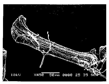
FIG. 1 is a scanning electron micrograph ("SEM") of a virgin PTFE floc
material, as prepared in Example 1.
FIG. 2 is a SEM of virgin PTFE floc material, as prepared in Example 1.
FIG. 3 is a SEM of a virgin PTFE floc material, as prepared in Example 1.
FIG. 4 is a SEM of a virgin PTFE floc material, as prepared in Example 1.
FIG. 5 is a SEM of a virgin PTFE floc material, as prepared in Example 2.
FIG. 6 is a SEM of a PTFE floc material according to the presently
preferred embodiment of the present invention, as prepared in Example 3.
FIG. 7 is a SEM of a PTFE floc material according to the presently
preferred embodiment of the present invention, as prepared in Example 3.
3
CA 02754104 2011-08-31
WO 2010/101701
PCT/US2010/023772
FIG. 8 is a SEM of a PTFE floc material according to the presently
preferred embodiment of the present invention, as prepared in Example 3.
FIG. 9 is a SEM of a PTFE floc material according to the presently
preferred embodiment of the present invention, as prepared in Example 3.
FIG. 10 is a SEM of a PTFE floc material according to the presently
preferred embodiment of the present invention, as prepared in Example 3.
FIG. 11 is a SEM of a PTFE floc material according to the presently
preferred embodiment of the present invention, as prepared in Example 3.
FIG. 12 is a SEM of a PTFE floc material according to the presently
preferred embodiment of the present invention, as prepared in Example 3.
FIG. 13 is a SEM of a PTFE floc material according to the presently
preferred embodiment of the present invention, as prepared in Example 3.
FIG. 14 is a SEM of a PTFE floc material according to the presently
preferred embodiment of the present invention, as prepared in Example 3.
FIG. 15 is a SEM of a PTFE floc material according to the presently
preferred embodiment of the present invention, as prepared in Example 4.
FIG. 16 is a SEM of a PTFE floc material according to the presently
preferred embodiment of the present invention, as prepared in Example 4.
FIG. 17 is a SEM of a PTFE floc material according to the presently
preferred embodiment of the present invention, as prepared in Example 4.
FIG. 18 is a SEM of a PTFE floc material according to the presently
preferred embodiment of the present invention, as prepared in Example 4.
FIG. 19 is a SEM of a PTFE floc material according to the presently
preferred embodiment of the present invention, as prepared in Example 4.
FIG. 20 is a SEM of a PTFE floc material according to the presently
preferred embodiment of the present invention, as prepared in Example 4.
Best Mode for Carrying Out Invention
The fluoropolymer material of the present invention is preferably
prepared from a fluoropolymer fiber, such as continuous fluoropolymer filament
yarn, which is made into floc or staple and processed in jet mill or a
cryogenic
grinder. In each process, the physical appearance of the fluoropolymer fibers
is
4
CA 02754104 2011-08-31
WO 2010/101701
PCT/US2010/023772
modified in a manner that improves the hydrophilicity of the material. This
occurs by forming deformations in the fluoropolymer fibers that are visible
using
scanning electron microscopy at magnifications as low as X120. The
deformations act to increase and roughen the surface area of the fibers by
tearing
the typically smooth exterior body and ends of the individual floc fibers and
providing the fibers with split ends, slits along the bodies of the fibers,
outwardly
extending, fibril-like members, and exposed interior fiber portions.
In the present invention, by "fluoropolymer fiber" it is meant a fiber
prepared from polymers such as polytetrafluoroethylene ("PTFE"), and polymers
generally known as fluorinated olefinic polymers, for example, copolymers of
tetrafluoroethylene and hexafluoropropene, copolymers of tetrafluoroethylene
and perfluoroalkyl-vinyl esters such as perfluoropropyl-vinyl ether and
perfluoroethyl-vinyl ether, fluorinated olefinic terpolymers including those
of the
above-listed monomers and other tetrafluoroethylene based copolymers. For the
purposes of this invention, the preferred fluoropolymer fiber is PTFE fiber.
In the present invention, by "split" it is meant a tear that extends along a
length of a fluoropolymer material and out through an end of the fiber. A
spilt
can appear as a crack through an end of the fiber or result in the formation
of
separated or partially separated fiber strands, each strand having a free end
and an
attached end. In some instances, the end of a fiber may include a single split
thereby giving rise to a pair of strands, which may or may not have the same
thickness. Alternatively, the end of a fiber may include many splits thereby
giving rise to many strands. In this instance, the end of the fiber can have a
frayed appearance depending on the number and lengths of the splits. A split
typically does not result in the removal of material or a substantial amount
of
material from the fiber. However, in some instances, a split can extend along
a
length of a fiber and result in the complete removal of a sliver-like portion
of the
fiber, or along the entire length of the fiber thus removing a side of the
fiber.
In the present invention, by "slit" it is meant a tear that extends partially
along a length of a fluoropolymer fiber but does not extend through one of the
opposing ends of the fiber. Slits often appear as an elongated, continuous
openings that extend into an interior of the fiber to a particular depth. Like
a
5
CA 02754104 2011-08-31
WO 2010/101701
PCT/US2010/023772
split, a slit typically does not result in the removal of material or a
substantial
amount of material from the fiber.
In the present invention, by "grain" it is meant a longitudinal arrangement
or pattern of fibril-like members. Often, a tear in the fluoropolymer fiber
will
expose an interior surface of the fiber. These interior surfaces can exhibit a
grain
running longitudinally along the axis of the fiber. The grain gives the
exposed
interior surface of the fiber the appearance of ridges extending lengthwise
along
the exposed interior surface.
In the present invention, by "fibril-like members" it is meant the
elongated pieces that make up the grain of a fluoropolymer fiber. Under the
various magnifications exhibited in the figures, the fibril-like members are
not
visible along a length of the exterior surface of the fibers. However, they
are
visible on the interior surfaces of the fluoropolymer fibers when the interior
surfaces are exposed, for example, by a tear. When the fluoropolymer fiber is
torn, exposing the interior surfaces of the fibers, a portion of the fibril-
like
members appear to become partially dislodged from the fibers and extend
outwardly therefrom. These fibril-like members have attached ends and free
ends
which extend outwardly from exposed interior surfaces of the fluoropolymer
fiber.
The fluoropolymer fiber of the present invention can be spun by a variety
of means, depending on the exact fluoropolymer composition desired. Thus, the
fibers can be spun by dispersion spinning; that is, a dispersion of insoluble
fluoropolymer particles is mixed with a solution of a soluble matrix polymer
and
this mixture is then coagulated into filaments by extruding the mixture into a
coagulation solution in which the matrix polymer becomes insoluble. The
insoluble matrix material may later be sintered and removed by oxidative
processes if desired. One method which is commonly used to spin PTFE and
related polymers includes spinning the polymer from a mixture of an aqueous
dispersion of the polymer particles and viscose, where cellulose xanthate is
the
soluble form of the matrix polymer, as taught for example in U.S. Pat. Nos.
3,655,853; 3,114,672 and 2,772,444. However, the use of viscose suffers from
some serious disadvantages. For example, when the fluoropolymer particle and
6
CA 02754104 2013-10-03
viscose mixture is extruded into a coagulation solution for making the matrix
polymer
insoluble, the acidic coagulation solution converts the xanthate into unstable
xantheic acid
groups, which spontaneously lose CS2, an extremely toxic and volatile
compound.
Preferably, the fluoropolymer fiber of the present invention is prepared using
a more
environmentally friendly method than those methods utilizing viscose. One such
method is
described in U.S. Pat. Nos. 5,820,984; 5,762,846, and 5,723,081. In general,
this method
employs a cellulosic ether polymer such as methylcellulose,
hydroxyethylcellulose,
methylhydroxypropylcellulose, hydroxypropylmethylcellulose,
hydroxypropylcellulose,
ethylcellulose or carboxymethylcellulose as the soluble matrix polymer, in
place of
viscose. Alternatively, if melt viscosities are amenable, filament may also be
spun directly
from a melt. Fibers may also be produced by mixing fine powdered fluoropolymer
with an
extrusion aid, forming this mixture into a billet and extruding the mixture
through a die to
produce fibers which may have either expanded or un-expanded structures. For
the
purposes of this invention, the preferred method of making the fluoropolymer
fiber is by
dispersion spinning where the matrix polymer is a cellulosic ether polymer.
The fluoropolymer fiber can be made into floc or staple using any number of
means
known in the art. Preferably, the fluoropolymer fiber is cut into floc or
staple by a
guillotine cutter, which is characterized by a to-and-fro movement of a
cutting blade.
Following cutting, the fluoropolymer fibers preferably have lengths ranging
between 127
microns and 115,000 microns.
The process for modifying the physical appearance of the fluoropolymer
materials
by forming deformations in the fibers is achieved by introducing mechanical
energy into
the fluoropolymer fibers to such a degree that the ends of the fibers are
split, slits are
formed in the bodies of the fibers, a grain of the fiber is exposed, and
fibril-like members
are extended outwardly from exposed interior surface portions of the fibers.
Preferably, the
processes do not substantially decrease the length of the individual fibers.
7
CA 02754104 2011-08-31
WO 2010/101701
PCT/US2010/023772
One suitable process includes entraining the fibers in an air stream,
directing the entrained fibers through an orifice and colliding the pieces
into one
another. This process is preferably carried out using a jet mill and jet
milling
processes, examples of which are described in U.S. Pat. Nos. 7,258,290;
6,196,482, 4,526,324; and 4,198,004. Another suitable process includes cooling
the fluoropolymer fibers to a cryogenic temperature of about -268 C or less,
depending on the low temperature embrittlement properties of the particular
fibers, and then grinding the fibers. This process is preferably carried out
using a
cryogrinder and cryogrinding processes, examples of which are described in
U.S.
Pat. Nos. 4,273,294; 3,771,729; and 2,919,862.
Jet mills and cryogrinders are conventionally used to pulverize materials
into fine particles or powder. For example, jet milling is a process that uses
high
pressure air to micronize friable, heat-sensitive materials into ultra-fine
powders.
Powder sizes vary depending on the material and application, but typically
ranges
from 75 to as fine as 1 micron can be prepared. Often materials are jet milled
when they need to be finer than 45 microns. Cryogenic grinding is a process
that
uses liquid nitrogen to freeze the materials being size-reduced and one of a
variety of grinding mechanisms to ground them to a powder distribution
depending on the application. Particle sizes of 0.1 micron can be obtained.
However, it has unexpectedly been found that jet or cryogenic milling can be
carried out on the fluoropolymers materials of the present invention without
the
materials being pulverized or size-reduced. More particularly, it has been
found
that the materials can be processed with a jet mill or a cryogenic grinding
mill
without substantially affecting the lengths of fibers, while at the same time
forming splits in the ends of the fibers, forming slits in the bodies of the
fibers,
forming outwardly extending, fibril-like members and exposing the interior
surfaces of the materials. Also, unexpectedly, these modifications have been
found to render the processed fluoropolymer materials hydrophilic thus
converting a hydrophobic material into a hydrophilic material, or in the
alternative, increasing or improving the hydrophilicity of the materials.
8
CA 02754104 2013-10-03
The present invention will be explained further in detail by the following
Examples. In each of the Examples, a 6.7 denier per filament continuous,
cellulosic ether-based PTFE filament yarn was prepared and cut with a
guillotine
cutter into virgin floc.
EXAMPLE 1
In Example 1, the virgin floc was cut into lengths of approximately 200 to
250 microns. As displayed in FIGS. 1 through 4, the virgin floc fibers had
smooth, nearly featureless exterior surfaces along the lengths thereof. The
ends
of the floc fibers were substantially smooth and nearly featureless as well,
with
the exception of the PTFE floc fibers shown in FIG. 4, which exhibited some
uneven areas which are believed to have resulted from the cutting process.
The wettability of the 200 to 250 microns virgin PTFE fiber floc was
tested. In a first test, 50 grams of the floc and 200 nil of deionized water
were
placed into a Waring blender and mixed for 30 seconds. Thereafter, the mixture
was observed. Immediately, the PTFE floc fibers that were not adhered to the
walls of the blender or floating on top of the water began to settle to the
bottom
of the blender. This resulted in the formation of three distinct mixture
portions
including a floc rich bottom portion, a water rich middle portion and a top
portion
composed of PTFE fiber floc floating on top of the middle portion. The floc in
the top portion appeared dry.
In a second test, the wettability of the PTFE fiber floc was determined by
placing 50 grams of the floc and 200 ml of deionized water into a WaringTm
blender, mixing the water and fibers for 30 seconds and immediately thereafter
siphoning a portion of the mixture into a syringe. As in the first test, the
PTFE
floc fibers quickly settled into three portions including a floc rich bottom
portion,
a water rich middle portion and a top portion composed of floc fibers floating
on
top of the middle portion.
The results evidenced that the 200 to 250 microns virgin PTFE fiber floc
was hydrophobic.
EXAMPLE 2
In Example 2, the virgin floc was cut into lengths of approximately 6350
microns. As displayed in FIG. 5, the virgin floc fibers had smooth, nearly
9
CA 02754104 2011-08-31
WO 2010/101701
PCT/US2010/023772
featureless exterior surfaces along the lengths thereof. These figures further
show
that floc fibers tended to clump together.
The wettability of the 6350 microns virgin PTFE fiber floc was tested.
Fifty grams of the floc and 200 ml of deionized water were placed into a
Waring
blender and mixed for 30 seconds. Thereafter, the mixture was observed.
Immediately, the PTFE floc fibers began to settle to the bottom of the
container.
This resulted in the formation of two distinct mixture portions including a
floc
rich bottom portion and a water rich top portion
The test results evidenced that the 6350 microns PTFE fiber floc was
hydrophobic.
EXAMPLE 3
In Example 3, a portion of the 200 to 250 microns virgin PTFE fiber floc
was processed by jet milling and examined. As shown in FIGS. 6 through 14, jet
mill processing of the fluoropolymer fiber floc modified the physical
appearance
of the fluoropolymer fibers. The modifications included surface deformations
caused by tearing of the fibers. The tearing resulted in the formation of
split fiber
ends, slits along the bodies of the fibers, and formation of outwardly
extending,
fibril-like members and the exposure of interior surfaces of the fibers. The
exposed interior surfaces of the fibers exhibited a grain that in certain
instances,
where a split resulted in the removal of an entire side of the fiber, extended
the
entire length of the fibers. The grain appeared to be formed by the fibril-
like
members.
The majority of the fibril-like members remained fully coupled to the
fiber surfaces after tearing thus providing the exposed interior surfaces with
a
number of longitudinally extending ridges. The ridges gave the exposed
interior
surfaces a rough appearance in contrast to the smooth exterior surfaces of the
fibers. In other instances, the fibril-like members became partially detached
from
the fibers and extended outwardly from the fiber surfaces. These fiber
surfaces
primarily included the exposed interior surfaces but also included areas along
the
edges formed between the exterior surfaces and exposed interior surfaces of
the
fibers. An example of an exposed interior surface is well depicted in FIGS. 6,
7
and 12. It is believed that the fibril-like members constitute individual or
small
CA 02754104 2011-08-31
WO 2010/101701
PCT/US2010/023772
groupings of elongated or drawn PTFE particles. The partially detached fibril-
like members were often bent or curved and had lengths in excess of 100
microns.
The slits appeared to form between groupings of the fibril-like members
and individual fibril-like members. The observed members had lengths that were
less than 20 microns and as long as 80 microns. The depth of the of the slits
was
difficult to determine, but it was found that some of the slits extended
through the
entire thickness or width of the PTFE fibers. A plurality of slits formed
within a
single fiber are well depicted in FIG. 8.
FIGS. 10 through 13 depict various splits through the ends of the PTFE
fibers. A typical frayed fiber end is shown in FIG. 10, the fiber being frayed
at
both ends. The frayed portions are exhibited as individual strands having free
ends and ends attached to the fiber. The fiber in FIG. 10 also appears to have
had
an entire side of the fiber split off from the fiber thus exposing an interior
surface
of the fiber that extends the length of the fiber. This occurrence is also
depicted
in FIGS. 6 and 7. FIG. 11 provides an example of a split that does not result
in a
strand having a free end but rather appears as a crack that extends through
the end
of the fiber.
The splits ranged in lengths from less than 1 micron to the entire length of
the fibers. In those instances where substantial fraying was observed, the
fiber
ends included splits in the range of 50 to 75 microns.
The wettability of the jet milled, 200 to 250 microns PTFE fiber floc was
tested. In a first test, 50 grams of the processed floc and 200 ml of
deionized
water were placed into a Waring blender and mixed for 30 seconds. Thereafter,
the mixture was observed. The mixture appeared as a homogenous, aqueous
dispersion of the fluoropolymer floc. No floc was observed settling at the
bottom
of the container, and none of the floc was observed floating on top of the
mixture.
The mixture maintained a homogenous state for several days even as the amount
of water in the container decreased by evaporation. Eventually, enough water
evaporated from the container that the wetted fluoropolymer floc took on the
consistency of dough.
11
CA 02754104 2011-08-31
WO 2010/101701
PCT/US2010/023772
In a second test, the wettability of the jet milled PTFE fiber floc was
determined by placing 50 grams of the processed floc and 200 ml of deionized
water into a Waring blender, mixing the water and fibers for 30 seconds and
immediately thereafter siphoning a portion of the mixture into a syringe. As
in
the first test, the mixture appeared as a homogenous, aqueous dispersion of
fluoropolymer floc. No floc was observed settling at the bottom of the
syringe,
and none of the floc was observed floating on top of the mixture. The
homogenous slurry flowed easily into and out of syringe on multiple occasions
exhibiting excellent flow characteristics
The tests results evidence that the jet milled, 200 to 250 microns PTFE
fiber floc was hydrophilic.
EXAMPLE 4
In Example 4, a portion of the 6350 microns virgin PTFE fiber floc was
processed by cryogenic grinding and examined. As shown in FIGS. 15 through
20, cryogenic milling of the fluoropolymer fiber floc modified the physical
appearance of the fluoropolymer fibers much like jet milling. Thus, the
cryogenic milled fibers included split fiber ends, slits along the bodies of
the
fibers, formation of outwardly extending, fibril-like members and exposure of
interior surfaces of the fibers. No substantial differences in the surface
morphology of the fibers milled by the cryogenic grinding process and the jet
milling processing were observed.
The wettability of the cryogenic milled, 6350 microns PTFE fiber floc
was tested. Fifty grams of the processed floc and 200 ml of deionized water
were
placed into a Waring blender and mixed for 30 seconds. Thereafter, the mixture
was observed. The mixture appeared as a homogenous, aqueous dispersion of the
fluoropolymer floc. No floc was observed settling at the bottom of the
container,
and none of the floc was observed floating on top of the mixture. For reasons
unknown, the cryogenic milled floc dispersed throughout the aqueous medium
and provided the mixture with a sponge-like consistency.
The tests results evidence that the cryogenic milled, 6350 microns PTFE
fiber floc was hydrophilic.
12
CA 02754104 2011-08-31
WO 2010/101701
PCT/US2010/023772
As will be apparent to one skilled in the art, various modifications can be
made within the scope of the aforesaid description. Such modifications being
within the ability of one skilled in the art form a part of the present
invention and
are embraced by the claims below.
13