Language selection

Search

Patent 2754338 Summary

Third-party information liability

Some of the information on this Web page has been provided by external sources. The Government of Canada is not responsible for the accuracy, reliability or currency of the information supplied by external sources. Users wishing to rely upon this information should consult directly with the source of the information. Content provided by external sources is not subject to official languages, privacy and accessibility requirements.

Claims and Abstract availability

Any discrepancies in the text and image of the Claims and Abstract are due to differing posting times. Text of the Claims and Abstract are posted:

  • At the time the application is open to public inspection;
  • At the time of issue of the patent (grant).
(12) Patent: (11) CA 2754338
(54) English Title: A SINGLE-ANTENNA VEHICLE TRANSPONDER WITH A POWER-SAVE FUNCTION
(54) French Title: UN TRANSPONDEUR DE VEHICULE A ANTENNE SIMPLE DOTE D'UNE FONCTION D'ECONOMIE D'ENERGIE
Status: Granted and Issued
Bibliographic Data
(51) International Patent Classification (IPC):
  • H04B 1/59 (2006.01)
  • G07B 15/06 (2011.01)
(72) Inventors :
  • ROGOE, JOHAN (Sweden)
(73) Owners :
  • KAPSCH TRAFFICCOM AB
(71) Applicants :
  • KAPSCH TRAFFICCOM AB (Sweden)
(74) Agent: SMART & BIGGAR LP
(74) Associate agent:
(45) Issued: 2019-12-31
(22) Filed Date: 2011-10-04
(41) Open to Public Inspection: 2012-04-05
Examination requested: 2016-09-30
Availability of licence: N/A
Dedicated to the Public: N/A
(25) Language of filing: English

Patent Cooperation Treaty (PCT): No

(30) Application Priority Data:
Application No. Country/Territory Date
10186530.1 (European Patent Office (EPO)) 2010-10-05

Abstracts

English Abstract


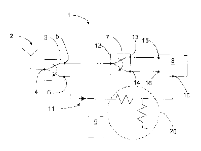
The present invention relates to a vehicle transponder (1) comprising an
active radio unit (8), an antenna (2), a wake-up unit (9) and a power
directing
means (3, 21, 22) which has a first port (4, 4', 4"), a second port (5, 5',
5")
and a third port (6, 6', 6"), where the power directing means (3, 21, 22) is
arranged to direct power from the first port (4, 4', 4") to the second port
(5, 5',
5") and/or the third port (6, 6', 6"). The antenna (2) is connected to the
first
port (4, 4', 4") and the second port (5, 5', 5') is connected to the radio
unit (8).
Furthermore, the third port (6, 6', 6") is connected both to a power detection
port (10) at the radio unit (8) and to the wake-up unit (9), such that during
a
first mode of operation, a part of a signal that is transmitted from the radio
unit (8) to the antenna (2) is coupled from the second port (5, 5', 5") to the
third port (6, 6', 6") and further fed to the power detection port (10). The
degree of signal that is coupled from the second port (5, 5', 5") to the third
port (6, 6', 6") is dependent on the connection properties between said
second port (5, 5', 5") and third port (6, 6', 6").


French Abstract

La présente invention concerne un transpondeur de véhicule (1) comprenant une unité radio active (8), une antenne (2), une unité de réveil (9) et un moyen de direction de puissance (3, 21, 22) qui comporte un premier port (4, 4', 4"), un deuxième port (5, 5', 5") et un troisième orifice (6, 6', 6"), où le moyen de direction de puissance (3, 21, 22) est disposé pour diriger la puissance du premier orifice (4, 4', 4") vers le deuxième orifice (5, 5', 5") ou le troisième orifice (6, 6', 6"). Lantenne (2) est connectée au premier port (4, 4', 4"), et le deuxième port (5, 5', 5') est connecté à lunité radio (8). En outre, le troisième port (6, 6', 6") est relié à la fois à un port de détection de puissance (10) de lunité radio (8) et à lunité de réveil (9), de sorte que pendant un premier mode de fonctionnement, une partie du signal transmis de lunité radio (8) à lantenne (2) est couplé du deuxième port (5, 5', 5") au troisième port (6, 6', 6") et alimente ensuite lentrée de détection de puissance (10). Le degré de signal qui est couplé du deuxième port (5, 5', 5") au troisième port (6, 6', 6") dépend des propriétés de connexion entre ledit deuxième port (5, 5', 5") et le troisième port (6, 6', 6").

Claims

Note: Claims are shown in the official language in which they were submitted.


9
CLAIMS
1. A vehicle transponder comprising:
an antenna, and
a power directing means, the power directing means having a first port, a
second
port and a third port, where the power directing means is arranged to direct
power from
the first port to the second port and/or the third port,
where the transponder further comprises an active radio unit and a wake-up
unit,
and
where furthermore the antenna is connected to the first port of the power
directing means and the second port of the power directing means is connected
to the
radio unit,
wherein the third port of the power directing means is connected both to a
power
detection port at the radio unit and to the wake-up unit, such that during a
first mode of
operation, a part of a signal that is transmitted from the radio unit to the
antenna is
coupled from the second port of the power directing means to the third port of
the power
directing means and further fed to the power detection port, enabling control
of
transmitted output power from the radio unit,
where a degree of coupling of a signal from the second port to the third port
is
dependent on connection properties between the second port and the third port.
2. The vehicle transponder according to claim 1, wherein the power
directing means
is in the form of a power dividing means, where, during the first mode of
operation, the
power dividing means is arranged to connect the first port of the power
dividing means
to the second port of the power dividing means, where a part of a signal that
is
transmitted from the radio unit to the antenna is coupled from the second port
of the
power dividing means to the third port of the power dividing means and further
fed to the
power detection port.
3. The vehicle transponder according to claim 1, wherein the power
directing means
is in the form of a first switch,

10
where, during the first mode of operation, the first switch is arranged to
connect
the first port of the first switch to the second port of the first switch,
where a part of a
signal that is transmitted from the radio unit to the antenna is coupled from
the second
port of the first switch to the third port of the first switch and further fed
to the power
detection port.
4. The vehicle transponder according to claim 1, wherein the transponder
further
comprises a second switch, where the second port of the power directing means
is
connected to the radio unit via the second switch, such that, during the first
mode of
operation, the signal that is transmitted from the radio unit to the antenna
is fed via the
second switch and the power directing means.
5. The vehicle transponder according to claim 1, wherein the wake-up unit
is
arranged to be connected to the antenna via the power directing means during a
second mode of operation, where, at reception of a certain signal via the
antenna, the
wake-up unit is arranged to initiate the first mode of operation, the power
directing
means being arranged to connect the antenna to the wake-up unit during the
second
mode of operation, and to connect the antenna to the second switch during the
first
mode of operation.
6. The vehicle transponder according to claim 1, wherein the third port of
the power
directing means is connected to the wake-up unit and the power detection port
via a
rectifying diode.
7. The vehicle transponder according to claim 1, wherein the second switch
comprises a first port, a second port and a third port, where the second
switch is
arranged to switch from the first port to either the second port or the third
port,
where the second port of the second switch is connected to a receive port of
the
radio unit, and the third port of the second switch is connected to a transmit
port of the
radio unit.

11
8. The vehicle transponder according to claim 1, wherein the vehicle
transponder is
positioned in a vehicle and arranged to communicate with an antenna at a road
side
station.
9. The vehicle transponder according to claim 1, wherein the third port of
the power
directing means is connected to the power detection port at the radio unit via
a resistor
power dividing network.

Description

Note: Descriptions are shown in the official language in which they were submitted.


CA 02754338 2011-10-04
TITLE
A single--antenna vehicle transponder with a power-save function
TECHNICAL FIELD
The present invention relates to a vehicle transponder comprising an antenna
and a power directing means, the power directing means having a first port, a
second port and a third port. The power directing means is arranged to direct
power from the first port to the second port and/or the third port. The
transponder further comprises an active radio unit and a wake-up unit, where
furthermore the antenna is connected to the first port of the power directing
means and the second port of the power directing means is connected to the
radio unit.
BACKGROUND ART
At some -places there is a demand for controlling the flow of vehicles, and
one way to perform such a control is to use fee collection systems, where
vehicles passing a road side station are debited a certain fee, where the fee
may vary, by way of example for different types of vehicles and for different
times.
Normally, each road side station is equipped to communicate to vehicle
transponders, which are positioned in the vehicles. Each transponder is
normally arranged to receive a signal from the toll station and to respond,
where the response for example comprises vehicle identification data.
Each transponder normally comprises a switch that is arranged to switch
between transmission and reception of the active radio unit and, if the
transponder comprises a single antenna, for example a switch or directional
coupler to couple the antenna to either the radio unit or wake-up circuitry
depending on the mode of operation.

2
A battery powered transponder is suitably equipped with power saving means
that is
arranged to start a power saving mode, where a certain stimuli signal wakes
the
transponder when it is in power saving mode. In this way, the transponder may
save
battery energy. In the power saving mode, the antenna is coupled to the wake-
up
circuitry.
Furthermore, in order to control transmitted output power from an active radio
unit, a
transponder is normally equipped with a directional coupler on the output,
where a
predetermined part of the transmitted power is fed back to a radio unit in the
transponder, allowing the radio unit to control the transmitted output power.
However, a transponder with power feedback and a wake-up circuitry comprises a
number of parts as indicated above, and there is a desire to obtain a less
complex
arrangement for obtaining the same functionality in a transponder.
SUMMARY OF THE INVENTION
The object of the present invention is to obtain a vehicle toll transponder
that comprises
a wake-up circuit and a feedback loop for transmitted output power, where the
number
of components is reduced.
This object is obtained by means of a vehicle transponder comprising an
antenna and a
power directing means, the power directing means having a first port, a second
port and
a third port. The power directing means is arranged to direct power from the
first port to
the second port and/or the third port. The transponder further comprises an
active radio
unit and a wake-up unit, where furthermore the antenna is connected to the
first port of
the power directing means and the second port of the power directing means is
connected to the radio unit. The third port of the power directing means is
connected
both to a power detection port at the radio unit and to the wake-up unit, such
that during
a first mode of operation, a part of a signal that is
CA 2754338 2018-01-08

3
transmitted from the radio unit to the antenna is coupled from the second port
of the
power directing means to the third port of the power directing means and
further fed to
the power detection port, enabling control of transmitted output power from
the radio
unit. A degree of signal that is coupled from the second port to the third
port is
dependent on the connection properties between the second port and third port.
According to an example, the power directing means is in the form of a first
switch,
where, during the first mode of operation, the first switch is arranged to
connect the first
port of the first switch to the second port of the first switch, where a part
of a signal that
is transmitted from the radio unit to the antenna is coupled from the second
port of the
first switch to the third port of the first switch and further fed to the
power detection port.
According to another example, the power directing means is in the form of a
power
dividing means, where, during the first mode of operation, the power dividing
means is
arranged to connect the first port of the power dividing means to the second
port of the
power dividing means, where a part of a signal that is transmitted from the
radio unit to
the antenna is fed from the second port of the power dividing means to the
third port of
the power dividing means and further fed to the power detection port.
According to another example, the transponder further comprises a second
switch,
where the second port of the power directing means is connected to the radio
unit via
the second switch, such that, during the first mode of operation, the signal
that is
transmitted from the radio unit to the antenna is fed via the second switch
and the
power directing means.
According to another example, the third port of the power directing means is
also
connected to the wake-up unit, where the wake-up unit is arranged to be
connected to
the antenna via the power directing means during a second mode of operation,
where,
at the reception of a certain signal via the
CA 2754338 2018-01-08

CA 02754338 2011-10-04
4
antenna, the wake-up unit is arranged to initiate the first mode of operation,
the power directing means being arranged to connect the antenna to the
wake-up unit during the second mode of operation, and to connect the
antenna to the second switch during the first mode of operation.
Other examples are evident from the dependent claims.
A number of advantages are evident from the present invention, primarily a
less complex arrangement in a transponder which still provides the same
functionality is obtained. In this way, a less expensive and less bulky
transponder is acquired.
BRIEF DESCRIPTION OF THE DRAWINGS
The present invention will now be described more in detail with reference to
the appended drawings, where:
Figure 1 schematically shows a vehicle and a road side station;
Figure 2 shows simplified schematics for a vehicle transponder according
to a first example of the present invention;
Figure 3 shows simplified schematics for a vehicle transponder according
to a second example of the present invention; and
Figure 4 shows simplified schematics for a vehicle transponder according
to a third example of the present invention.
DETAILED DESCRIPTION
With reference to Figure 1, a vehicle 17 that passes a road side station 19 is
arranged to communicate with the road side station 19 by means of an on-
board unit in the form of a vehicle transponder 1. The communication is
performed in order to execute information exchange between the road side

CA 02754338 2011-10-04
station and the transponder, where the information exchange is used for
debiting the vehicle a certain road toll fee. Such a debiting may be performed
in many ways, and these details will not be discussed here, since they are
well-known.
5
With reference to Figure 2, showing a first example, the vehicle transponder
1 comprises an antenna 2 and a first switch 3, where the first switch 3
comprises a first port 4, a second port 5 and a third port 6. The first switch
3
is arranged to switch from the first port 4 to either the second port 5 or the
third port 6.
The transponder further comprises an active radio unit 8, where the antenna
2 is connected to the first port 4 of the first switch 3, and the second port
5 of
the first switch 3 is connected to the radio unit 8.
The transponder further comprises a second switch 7, where the second
switch 7 is arranged to switch between a transmitting mode and a receiving
mode of the radio unit. 8. The second switch 7 comprises a first port 12, a
second port 13 and a third port 14, where the second switch 7 is arranged to
switch from the first port 12 to either the second port 13 or the third port
14.
The second port 13 of the second switch 7 is connected to a receive port 15
of the radio unit 8, and the third port 14 of the second switch 7 is connected
to a transmit port 16 of the radio unit 8.
During a first mode of operation, a signal that is transmitted from the radio
unit 8 to the antenna 2 is fed via the second switch 7 and the first switch 3,
and a signal that is received is fed from the antenna 2 to the radio unit 8
via
the first switch 3 and the second switch 7.
The third port 6 of the first switch 3 is connected to a wake-up unit 9 that
is
connected to the antenna 2 via the first switch 3 during a second mode of

CA 02754338 2011-10-04
6
operation, where, at the reception of a certain signal via the antenna 2, the
wake-up unit 9 is arranged to initiate the first mode of operation.
The first switch 3 is thus arranged to connect the antenna 2 to the wake-up
unit 9 during the second mode of operation, and to connect the antenna 2 to
the second switch 7 and further to the radio unit 8 during the first mode of
operation.
According to the present invention, the third port 6 of the first switch 3 is
.. connected to a power detection port 10 at the radio unit 8. In the
transmitting
mode, during the first mode of operation, where the first switch 3 connects
the first port 4 of the first switch 3 to the second port 5 of the first
switch 3, a
part of a signal that is transmitted from the radio unit 8 to the antenna 2 is
coupled from the second port 5 of the first switch 3 to the third port 6 of
the
first switch 3. The coupled signal is further fed to the power detection port
10,
where the degree of coupling is dependent on the isolation between said
second port 5 and third port 6.
In this way, by measuring the power of the coupled signal, it is possible to
control transmitted output power from the radio unit 8.
In accordance with the present invention, the first switch 3, which basically
is
used for switching between the first mode of operation and the second mode
of operation, i.e. between transmission/reception and power saving, is also
used as a coupler for coupling a predetermined part of transmitted power
back to the radio unit 8 in a feed-back loop.
In a second example, with reference to Figure 3, a directional coupler 21 is
used instead of the first switch. The directional coupler 21 comprises a first
port 4', a second port 5' and a third port 6', where these ports 4', 5', 6'
correspond to the ports 4, 5, 6 of the first switch 3 in the first example.

CA 02754338 2011-10-04
7
In a third example, with reference to Figure 4, a power divider 22 is used
instead of the first switch. The power divider 22 comprises a first port 4", a
second port 5" and a third port 6", where these ports 4", 5", 6" correspond to
the ports 4, 5, 6 of the first switch 3 in the first example.
In the second and third example, the first port 4', 4" is always connected to
both the second port 5', 5" and the third port 6", 6", but with a certain
degree
of connection that depends on the coupling factor at the directional coupler
21 and the power division properties of the power divider 22.
Generally, the directional coupler 21 and the power divider 22 may be
regarded as power dividing means 21, 22.
Thus, during the first mode of operation, the power dividing means 21, 22 is
arranged to connect the first port 4', 4'' of the power dividing means 21, 22
to
the second port 5', 5" of the power dividing means 21, 22, where a part of a
signal that is transmitted from the radio unit 8 to the antenna 2 is fed from
the
second port 5', 5" of the power dividing means 21, 22 to the third port 6', 6"
of the power dividing means 21, 22 and further fed to the power detection
port 10.
Generally, for all the examples, the first switch 3, the directional coupler
21,
the power divider 22 and similar devices which are possible to use at their
position to enable the antenna 2 to be connected to
- the wake-up circuit 9,
- the receive port 15 and the transmit port 16 of the radio unit 8, and
- the power detection port 10,
may be regarded as a power directing means 3, 21, 22. The degree of signal
that is directed from the second port 5, 5', 5" to the third port 6, 6', 6" is
dependent on the connection properties between said second port 5, 5', 5"
and third port 6, 6', 6".

CA 02754338 2011-10-04
8
The present invention is not limited to the embodiments shown above, but
may vary freely within the scope of the dependent claims. For example, the
third port 6 of the first switch 3 is preferably connected to the wake-up unit
9
and the power detection port 10 via a rectifying diode 11. Furthermore, the
third port 6 of the first switch 3 may be connected to the power detection
port
at the radio unit 8 via a resistor power dividing network 20.
By means of the present invention, one rectifying diode 11 may be used for
10 both the wake-up circuit 9 and the power detection port 10. The
rectifying
diode may alternatively be regarded as a schematic representation of a
rectifying circuit, comprising a number of rectifying diodes.
The power detection port does not have to be positioned at 10 the radio unit
8, but may be positioned at a separate control unit, which in turn controls
the
radio unit 8.
The second switch 7 may be realized in any suitable way.
The radio unit may comprise a chip arranged for Wireless Access in
Vehicular Environment (WAVE), which is a standard for Dedicated Short
Range Communications (DSRC).
The transponder may be used for any kind of communication between a road
side station and a vehicle, not only communication related to fee collection,
thus not only being constituted by a vehicle toll transponder, but generally
by
any type of vehicle transponder.

Representative Drawing
A single figure which represents the drawing illustrating the invention.
Administrative Status

2024-08-01:As part of the Next Generation Patents (NGP) transition, the Canadian Patents Database (CPD) now contains a more detailed Event History, which replicates the Event Log of our new back-office solution.

Please note that "Inactive:" events refers to events no longer in use in our new back-office solution.

For a clearer understanding of the status of the application/patent presented on this page, the site Disclaimer , as well as the definitions for Patent , Event History , Maintenance Fee  and Payment History  should be consulted.

Event History

Description Date
Maintenance Request Received 2024-09-23
Maintenance Fee Payment Determined Compliant 2024-09-23
Common Representative Appointed 2020-11-07
Grant by Issuance 2019-12-31
Inactive: Cover page published 2019-12-30
Common Representative Appointed 2019-10-30
Pre-grant 2019-10-24
Inactive: Final fee received 2019-10-24
Letter Sent 2019-06-18
Notice of Allowance is Issued 2019-06-18
Inactive: Q2 passed 2019-06-05
Inactive: Approved for allowance (AFA) 2019-06-05
Amendment Received - Voluntary Amendment 2018-12-24
Inactive: S.30(2) Rules - Examiner requisition 2018-06-26
Inactive: Report - No QC 2018-06-24
Amendment Received - Voluntary Amendment 2018-01-08
Inactive: Report - No QC 2017-07-10
Inactive: S.30(2) Rules - Examiner requisition 2017-07-10
Letter Sent 2016-10-06
Request for Examination Received 2016-09-30
All Requirements for Examination Determined Compliant 2016-09-30
Request for Examination Requirements Determined Compliant 2016-09-30
Change of Address or Method of Correspondence Request Received 2015-10-01
Application Published (Open to Public Inspection) 2012-04-05
Inactive: Cover page published 2012-04-04
Inactive: IPC assigned 2011-12-20
Inactive: First IPC assigned 2011-12-20
Amendment Received - Voluntary Amendment 2011-11-22
Inactive: IPC assigned 2011-10-28
Application Received - Regular National 2011-10-20
Inactive: Filing certificate - No RFE (English) 2011-10-20
Filing Requirements Determined Compliant 2011-10-20

Abandonment History

There is no abandonment history.

Maintenance Fee

The last payment was received on 2019-09-20

Note : If the full payment has not been received on or before the date indicated, a further fee may be required which may be one of the following

  • the reinstatement fee;
  • the late payment fee; or
  • additional fee to reverse deemed expiry.

Please refer to the CIPO Patent Fees web page to see all current fee amounts.

Fee History

Fee Type Anniversary Year Due Date Paid Date
Application fee - standard 2011-10-04
MF (application, 2nd anniv.) - standard 02 2013-10-04 2013-09-10
MF (application, 3rd anniv.) - standard 03 2014-10-06 2014-09-23
MF (application, 4th anniv.) - standard 04 2015-10-05 2015-09-22
MF (application, 5th anniv.) - standard 05 2016-10-04 2016-09-21
Request for examination - standard 2016-09-30
MF (application, 6th anniv.) - standard 06 2017-10-04 2017-09-22
MF (application, 7th anniv.) - standard 07 2018-10-04 2018-09-21
MF (application, 8th anniv.) - standard 08 2019-10-04 2019-09-20
Final fee - standard 2019-12-18 2019-10-24
MF (patent, 9th anniv.) - standard 2020-10-05 2020-09-21
MF (patent, 10th anniv.) - standard 2021-10-04 2021-09-21
MF (patent, 11th anniv.) - standard 2022-10-04 2022-09-26
MF (patent, 12th anniv.) - standard 2023-10-04 2023-09-25
MF (patent, 13th anniv.) - standard 2024-10-04 2024-09-23
Owners on Record

Note: Records showing the ownership history in alphabetical order.

Current Owners on Record
KAPSCH TRAFFICCOM AB
Past Owners on Record
JOHAN ROGOE
Past Owners that do not appear in the "Owners on Record" listing will appear in other documentation within the application.
Documents

To view selected files, please enter reCAPTCHA code :


To view images, click a link in the Document Description column. To download the documents, select one or more checkboxes in the first column and then click the "Download Selected in PDF format (Zip Archive)" or the "Download Selected as Single PDF" button.

List of published and non-published patent-specific documents on the CPD .

If you have any difficulty accessing content, you can call the Client Service Centre at 1-866-997-1936 or send them an e-mail at CIPO Client Service Centre.


Document
Description 
Date
(yyyy-mm-dd) 
Number of pages   Size of Image (KB) 
Abstract 2011-10-04 1 25
Description 2011-10-04 8 301
Claims 2011-10-04 3 108
Drawings 2011-10-04 4 30
Representative drawing 2012-03-08 1 5
Cover Page 2012-03-28 2 45
Description 2018-01-08 8 286
Claims 2018-12-24 3 96
Representative drawing 2019-11-08 1 5
Cover Page 2019-12-20 1 39
Confirmation of electronic submission 2024-09-23 3 78
Filing Certificate (English) 2011-10-20 1 157
Reminder of maintenance fee due 2013-06-05 1 113
Reminder - Request for Examination 2016-06-07 1 117
Acknowledgement of Request for Examination 2016-10-06 1 177
Commissioner's Notice - Application Found Allowable 2019-06-18 1 163
Correspondence 2015-10-01 6 186
Request for examination 2016-09-30 2 65
Examiner Requisition 2017-07-10 3 176
Amendment / response to report 2018-01-08 8 289
Examiner Requisition 2018-06-26 3 181
Amendment / response to report 2018-12-24 9 323
Prosecution correspondence 2011-11-22 2 73
Courtesy - Office Letter 2019-06-18 1 64
Final fee 2019-10-24 2 79