Note: Descriptions are shown in the official language in which they were submitted.
CA 02754858 2011-09-08
WO 2010/114670
PCT/US2010/026287
BUCKLE
BACKGROUND
[0001] One method of coupling of two straps or webbings together is with
the use
of a buckle and catch arrangement. In this arrangement, a buckle coupled to a
first
webbing is designed to selectively retain the catch that is attached to a
second webbing.
The use of the buckle and catch arrangement to selectively couple webbings
together is
commonly used in safety harnesses such as fall protection harnesses. One
common
method of attaching an end of a webbing to a buckle is with the use of a knurl
bar and a
webbing retaining member. A knurl bar can more generally be referred to as a
slide.
Movement of a safety harness in use tends to loosen the webbing with this
slide
attaching arrangement. Hence, the webbing must be tightened periodically
during use.
The loosening and the required subsequent tightening of the webbing in the
slide
attaching arrangement are inconvenient and cause the webbing to wear.
Reduction of
wear on webbing of a fall protection harness is critical for the harnesses
long term
performance and proper fit to maximize safety.
[0002] For the reasons stated above and for other reasons stated below
which will
become apparent to those skilled in the art upon reading and understanding the
present
specification, there is a need in the art for a method of maintaining proper
fit and
reducing wear of webbing that is engaged with a slide of a buckle.
SUMMARY OF INVENTION
[0003] The above-mentioned problems of current systems are addressed by
embodiments of the present invention and will be understood by reading and
studying
the following specification. The following summary is made by way of example
and
not by way of limitation. It is merely provided to aid the reader in
understanding some
of the aspects of the invention.
[0004] In one embodiment, a buckle is provided. The buckle includes a
connecting
portion, a slide and locking member. The connecting portion is configured to
selectively engage an engaging portion of a first webbing. The slide of the
buckle is
configured to engage a second webbing and the locking member is configured to
selectively press the second webbing on the slide.
1
CA 02754858 2014-11-04
BRIEF DESCRIPTION OF TIIE DRAWINGS
[0005] The present invention can be more easily understood and further
advantages
and uses thereof more readily apparent, when considered in view of the
detailed
description and the following figures in which:
[0006] Figure 1 is a front prospective view of a buckle and catch of one
embodiment of the present invention;
[0007] Figure 2 is an exploded front perspective view of the buckle of
Figure 1;
[0008] Figure 3 is an exploded back perspective view of the buckle of
Figure 1;
[0009] Figure 4 is a front view of a buckle of Figure 1 having a locking
member
engaged with a webbing on a slide of one embodiment;
100101 Figure 5 is a side cross-sectional view of the buckle of Figure 4;
[0011] Figure 6 is a front view of a buckle of Figure 1 having the locking
member
not engaged with the webbing on the slide of one embodiment;
[0012] Figure 7 is a side cross-sectional view of the buckle of Figure 6;
10013] Figure 8 is a rear view of a safety harness on one embodiment of the
present
invention; and
[0014] Figure 9 is an exploded front perspective view of another embodiment
of a
buckle of the present invention.
[0015] In accordance with common practice, the various described features
are not
drawn to scale but are drawn to emphasize specific features relevant to the
present
invention. Reference characters denote like elements throughout Figures and
text.
DETAILED DESCRIPTION
[0016] In the following detailed description, reference is made to the
accompanying
drawings, which form a part hereof, and in which is shown by way of
illustration
specific embodiments in which the inventions may be practiced. These
embodiments
are described in sufficient detail to enable those skilled in the art to
practice the
invention, and it is to be understood that other embodiments may be utilized
and that
mechanical changes may be made. The following detailed description is,
therefore, not to be taken in a
2
CA 02754858 2011-09-08
WO 2010/114670
PCT/US2010/026287
limiting sense, and the scope of the present invention is defined only by the
claims and
equivalents thereof.
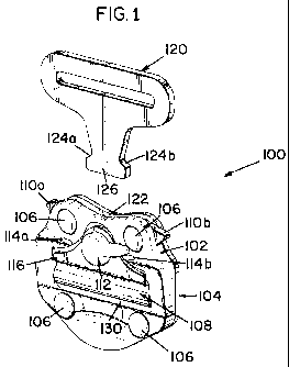
[0017] Embodiments of the present invention provide a system of pressing a
strap
on a slide of a buckle to prevent the strap from loosing up. Referring to
Figure 1, a
front assembled view of a buckle 100 of one embodiment is illustrated. As
illustrated,
the buckle 100 includes a first plate 102 and a second plate 104. The first
plate 102 is
coupled to the second plate 104 via rivets 106. A slide 108 is coupled between
the first
and second plates 102 and 104. Moreover, openings in the first and second
plates, such
as opening 130 of the first plate 102, allow for access of the slide 108.
Sandwiched
between the first plate 102 and the second plate 104 are pawls 110A and 110B
that
make up a connecting portion of the buckle 100. The pawls 110A and 110B engage
shoulder portions 124A and 124B near an engaging end 126 of a catch 120 to
lock the
catch 120 in the buckle 100. In particular, the catch 120 (or engaging portion
120)
becomes engaged when it is inserted in an opening 127 in the buckle 100 that
is
between the pawls 110A and 110B and the plates 102 and 104. The catch 120 can
generally be referred to as the engaging portion 120. In embodiments, a cam
knob 112
is used to move a locking plate 116 to selectively engage a strap 402 (shown
in Figure
4) on the slide 108. The cam knob 112 can be rotated between a locked and an
unlocked position. The rotation of the cam knob 112 is contained within stops
114A
and 114B. Operation and formation of the cam knob 112 is described below.
[0018] In Figure 2, an exploded front perspective view of the buckle 100
is
illustrated. As illustrated, the first plate 102 includes opening 130 has
discussed above.
Opening 130 is rectangular in shape. The second plate 104 also includes a
rectangular
opening 212. The slide 108 has a cylindrical mid portion 213 around which a
strap 402
(or webbing) (shown in Figure 4) is engaged. The slide 108 further has a first
end
214A and a second end 214B. As illustrated, the first end and the second end
214A and
214B each include flat surfaces that abut inner surfaces of the first 102 and
second
plates 104 when the first and second plates 102 and 104 are coupled together.
This
arraignment slidably retains the slide 108 in a within plates 102 and 104 of
the buckle
100. The cylindrical mid portion 213 of the knur bar 108 is received in the
openings
130 and 212 of the respective first and second plates 102 and 212. In one
embodiment
3
CA 02754858 2011-09-08
WO 2010/114670
PCT/US2010/026287
the surface of cylindrical mid portion 213 of the slide 108 has knurling (not
shown) to
increase friction.
[0019] The pawls 110A and 110B are pivotally coupled between the first
plate 102
and the second plate 104 via rivets 106. Biasing members 204A and 204B bias
the
respective pawls 110A and 110B to a select pivot rotational position that
engages catch
120 when the catch 120 is inserted in the opening 127 between the pawls 110A
and
110B of the buckle 100. In the embodiment of Figure 2, the locking member 116
is
generally L-shaped having a first portion 232 and a second portion 234. The
first
portion 232 of the locking member 116 has a generally oval shaped passage 230.
A
first side 221 of the first plate 102 has a recess 202 shaped to receive the
first portion
232 of the locking member 116. The second portion 234 of the locking member
116
fits in opening 130 of the first plate 102. The cam knob 112 includes an
activation
portion 252 and a retaining portion 250. The retaining portion 250 extends
from the
activation portion 252 of the cam knob 112 as illustrated. The first plate 102
of the
buckle 100 includes a retaining aperture 203 that is in recess 202. The
retaining portion
250 of the cam knob 112 extends through retaining aperture 203 of the first
plate 102.
A fastener 218 engages the retaining portion 250 of the cam knob 112 to retain
the cam
knob 112 in the buckle 100. Other types of fastener systems are contemplated,
such as
but not limited to, threadably engaging systems. The activation portion 252 of
the cam
knob 112 is received in the oval shaped passage 230 of the locking member 116.
Rotation of the cam knob 112 causes the activation portion 252 (which is also
generally
oval in shape in one embodiment) to engage the generally oval shaped passage
230 of
the locking member 116 to move the locking member 116 in relation to the first
plate
102. Movement of the locking member 116 is further discussed below.
[0020] Figure 3 is an exploded back perspective view of buckle 100. This
view
further illustrates how the components come together to form buckle 100. For
example, biasing member 204A is positioned between portion 306A of pawl 110A
and
recess 304A of the first plate 102. Similarly, biasing member 204B is
positioned
between portion 306B of pawl 110B and recess 304B of the first plate 102. The
first
pawl 110A and the second pawl 110B are both pivoted about a respective rivet
106 that
is received in a respective aperture 208 of the first plate and a respective
aperture 210 in
the second plate 104. As discussed above, the biasing members 204A and 204B
(which
4
CA 02754858 2011-09-08
WO 2010/114670
PCT/US2010/026287
are springs in this embodiment) pivotally bias the respective pawls 110A and
110B to
retain a catch, such as catch 120 of Figure 1. As further illustrated in
Figure 3, the
bottom portion of the first and second plates 102 and 104 are coupled together
by rivets
106 passing through respective apertures 206 in the first plate 102 and
respective
apertures 210 in the second plate 104. This embodiment further includes a
recess 302
in a second side 310 of the first plate 102 in which the retaining member 218
is
received.
[0021] Referring to Figure 4, a front view of buckle 100 having a strap or
webbing
402 coupled to the slide 214 is illustrated. Figure 4 illustrates the locking
member 116
in a locked position. As illustrated, in this embodiment the cam knob 112 is
rotated to
stop 114B on the first plate 102. This causes the locking member 116 to slide
toward
the webbing 402 on the slide 108. Gap 405 illustrates the locking plate 116
has been
moved toward the slide 108. The locked position is further illustrated in the
cross-
sectional side view of the bracket 100 in Figure 5. As illustrated, the second
portion
234 of the locking plate 116 engages the webbing 402 on the slide 108 to
prevent the
webbing 402 from moving in the buckle 100. In particular, the engaged locking
plate
increases friction between the strap 402, the slide 108 and first plate 102 to
reduce the
possibility of the strap 402 moving relative to the slide 108 during use. Also
illustrated
in Figures 4 and 5 is webbing retaining member 404. The webbing retaining
member
404 retains an end of the webbing 402 against itself and assists in keeping
the webbing
402 around the slide 108 of the buckle 100. The engagement of the locking
member
116 on the webbing 402 helps prevent the webbing 402 from loosening in
relation to
the slide 108 and the webbing retaining member 404.
[0022] Figure 6, illustrates the locking member 116 in an unlocked
position. In this
front view, buckle 100 has webbing 402 coupled to the slide 108. As
illustrated, in this
embodiment the cam knob 112 is rotated to stop 114A on the first plate 102.
This
causes the locking member 116 to move away from the webbing 402 on the slide
108.
Gap 602 illustrates the locking plate 116 has been moved away from the slide
108 as
compared to the gap 404 of Figure 4. The unlocked position is further
illustrated in the
cross-sectional side view of the bracket 100 in Figure 5. As illustrated, the
second
portion 234 of the locking plate 116 is not engaged with the webbing 402 on
the slide
108.
CA 02754858 2011-09-08
WO 2010/114670
PCT/US2010/026287
[0023] Figure 8 illustrates a rear view of a safety harness 550 of one
embodiment
of the present invention. As illustrated, the safety harness 550 includes a
plurality of
webbing (or straps) that are secured around a user. In particular, the webbing
includes
shoulder webbing 566A and 566B, front webbing 568A and 568B, back webbing 570A
and 570B, seat webbing 572, hip webbing 571 and leg webbing 574A and 574B. In
the
embodiment of the Figure 8, a single webbing forms webbing 568A, 566A and 570B
and a single webbing forms 568B, 566B and 570A. Back pad 560 is positioned on
the
back of a user. A D-ring 564 is coupled to the back pad 560 and straps 570A
and
570B. This D-ring 564 is used to couple the harness 550 to a support structure
via a
lanyard or lifeline. The hip webbing 571 retains the hip pad 562 around a
user's hip.
Attached to the hip webbing 571 are D-rings 580A and 580B used to position the
user
when in use. In embodiments, buckles such as buckle 100 described above are
used to
connect select webbings. In particular, buckle 552 is selectively coupled to
catch 554
to attach the webbing across the chest of the user. Buckles 556 and 558 are
coupled to
respective catches 555 and 557 to strap the leg webbings 574A and 574B around
legs
of the user. Buckles 552, 556 and 558 include locking members and cam knobs
such as
locking member 116 and cam knob 112 discussed above to selectively lock
respective
webbing on slides, such as slide 108.
[0024] Referring to Figure 9 an exploded front perspective view of another
embodiment of a buckle 900 is illustrated. This embodiment also includes a
first plate
902 and a second plate 904. A slide 938 is positioned between the first plate
902 and
the second plate 904. In particular, ends 937A and 137B having flat surfaces
of the
slide 938 are slidably contained between the first and second plates 902 and
904 while
a mid portion 937 of the slide 938 is received in opening 932 of the first
plate 902 and
opening 956 of the second plate 904. In one embodiment, the slide includes a
knurled
surface. The embodiment of Figure 9 further includes a mid plate 944 that is
sandwiched between the first plate 902 and the second plate 904. The mid plate
944
includes a cutout section 946 to receive the slide 937. The mid plate 944
further
includes alignment pins 954 that are received in alignment apertures 960 in
the second
plate and alignment pins 952 that are received in alignment apertures 960 in
the first
plate 902. Pawls 942A and 942B are pivotally coupled between the first and
second
plates via rivets 906. In particular, pawls 942A and 942B are pivotally
coupled by
6
CA 02754858 2011-09-08
WO 2010/114670
PCT/US2010/026287
rivets 906 passing through apertures 934A and 934B in the first plate 902,
apertures
943A and 943B in pawls 942A and 942B respectively and apertures 958A and 958B
in
the second plate 904. Pawl 942A is biased by biasing member 940A. In
particular, a
first end of biasing member 940A engages surface 941A of pawl 942A and surface
950A of the mid plate 944. Pawl 942B is biased by biasing member 940B. In
particular, a first end of biasing member 940B engages surface 941B of pawl
942B and
surface 950B of the mid plate 944. The biasing members 940A and 940B bias the
pawls 942A and 942B to engage a catch such as catch 120 of Figure 1. The first
plate
902, the mid plate 944 and the second plate 904 are further coupled together
by rivets
906. In particular, a rivet 906 passing through aperture 934C of the first
plate 902,
aperture 948A of the mid plate 944 and aperture 958C of the second plate and a
rivet
906 passing through aperture 934D of the first plate 902, aperture 948B of the
mid
plate 944 and aperture 958D of the second plate 904 couple a lower portion of
the first
plate 902, the mid plate 944 and the second plate 904 together.
[0025] The buckle 900 of Figure 9 further includes a third plate 918 and a
fourth
plate 922. The fourth plate 922 is sandwiched between the third plate 918 and
the first
plate 902. The fourth plate 922 has alignment apertures 960 that receive
alignment pins
952 of the mid plate 944. The third plate 918 and the fourth plate 922 are
attached to
the first plate 902 and the second plate 904 via rivets 906 passing through
apertures
920A and 920B in the third plate 918 and apertures 926A and 926B in the fourth
plate
922. The fourth plate 922 includes a cutout section 921 that is positioned
around an
upper portion of opening 932 of the first plate 902. This embodiment of the
buckle 900
also includes a locking member 910. The locking member 910 is generally L-
shaped
having a first portion 914 and a second portion 912. The third plate 918 has a
cutout
section 919 that is in the shape of the first portion of 914 of the locking
member 910.
The first portion 914 of the locking member 910 is received in cutout section
919 of the
third plate 918. The first portion 914 of the locking member 910 includes an
oval
shaped passage 916 that is aligned with aperture 924 in the fourth plate 922
and
aperture 930 in the first plate 902. Cam knob 908 includes and activation
portion, such
as activation portion 252 illustrated in Figure 3 that is generally oval in
shape. The
activation portion 252 is received in the oval shape passage 916 in the first
portion 914
of the locking mechanism 910. Cam knob 908 further includes a retaining
portion,
7
CA 02754858 2011-09-08
WO 2010/114670
PCT/US2010/026287
such as retaining portion 250 of Figure 3 that extends from the activation
portion 252.
The retaining portion 250 of cam knob 908 is received through aperture 924 of
the
fourth plate 922 and aperture 930 of the first plate 902. A fastener 936 is
attached to
the retaining portion 250 of cam knob 908 to retain activation portion 352 of
the cam
knob 908 in the oval shaped passage 916 of the locking member 910.
[0026] Although specific embodiments have been illustrated and described
herein,
it will be appreciated by those of ordinary skill in the art that any
arrangement, which is
calculated to achieve the same purpose, may be substituted for the specific
embodiment
shown. This application is intended to cover any adaptations or variations of
the
present invention. Therefore, it is manifestly intended that this invention be
limited
only by the claims and the equivalents thereof.
8