Note: Descriptions are shown in the official language in which they were submitted.
CA 02754905 2011-09-08
WO 2010/107949 PCT/US2010/027715
1
METHOD AND APPARATUS FOR DISTRACTING A JOINT,
INCLUDING THE PROVISION AND USE OF
A NOVEL JOINT-SPACING BALLOON CATHETER
AND A NOVEL INFLATABLE PERINEAL POST
Inventors
Julian Nikolchev
Hal David Martin
Chris Pamichev
James Flom
William Kaiser
Paritosh Ambekar
Geoff Willis
Lynette Ross
Matthew Frushell
Michael Leunig
Andrew Lantz
Reference To Pending Prior Patent Applications
This patent application claims benefit of:
(i) pending prior U.S. Provisional Patent
Application Serial No. 61/210,315, filed 03/17/2009 by
Julian Nikolchev et al. for JOINT SPACING BALLOON
CATHETER (Attorney's Docket No. FIAN-28 PROV);
(ii) pending prior U.S. Provisional Patent
Application Serial No. 61/268,340, filed 06/11/2009 by
Julian Nikolchev et al. for METHOD AND APPARATUS FOR
DISTRACTING A JOINT, INCLUDING THE PROVISION AND USE
CA 02754905 2011-09-08
WO 2010/107949 PCT/US2010/027715
- 2 -
OF A NOVEL JOINT-SPACING BALLOON CATHETER AND A NOVEL
INFLATABLE PERINEAL POST (Attorney's Docket No.
FIAN-42 PROV);
(iii) pending prior U.S. Provisional Patent
Application Serial No. 61/278,744, filed 10/09/2009 by
Julian Nikolchev et al. for METHOD AND APPARATUS FOR
DISTRACTING A JOINT, INCLUDING THE PROVISION AND USE
OF A NOVEL JOINT-SPACING BALLOON CATHETER AND A NOVEL
INFLATABLE PERINEAL POST (Attorney's Docket No.
FIAN-49 PROV); and
(iv) pending prior U.S. Provisional Patent
Application Serial No. 61/336,284, filed 01/20/2010 by
Julian Nikolchev et al. for METHOD AND APPARATUS FOR
DISTRACTING A JOINT, INCLUDING THE PROVISION AND USE
OF A NOVEL JOINT-SPACING BALLOON CATHETER AND A NOVEL
INFLATABLE PERINEAL POST (Attorney's Docket No.
FIAN-53 PROV).
The four (4) above-identified patent applications
are hereby incorporated herein by reference.
Field Of The Invention
This invention relates to surgical methods and
apparatus in general, and more particularly to methods
and apparatus for treating a hip joint.
Background Of The Invention
The Hip Joint In General
CA 02754905 2011-09-08
WO 2010/107949 PCT/US2010/027715
- 3 -
The hip joint is a ball-and-socket joint which
movably connects the leg to the torso. The hip joint
is capable of a wide range of different motions, e.g.,
flexion and extension, abduction and adduction, medial
and lateral rotation, etc. See Figs. 1A, 1B, 1C and
1D.
With the possible exception of the shoulder
joint, the hip joint is perhaps the most mobile joint
in the body. Significantly, and unlike the shoulder
joint, the hip joint carries substantial weight loads
during most of the day, in both static (e.g., standing
and sitting) and dynamic (e.g., walking and running)
conditions.
The hip joint is susceptible to a number of
different pathologies. These pathologies can have
both congenital and injury-related origins. In some
cases, the pathology can be substantial at the outset.
In other cases, the pathology may be minor at the
outset but, if left untreated, may worsen over time.
More particularly, in many cases, an existing
pathology may be exacerbated by the dynamic nature of
the hip joint and the substantial weight loads imposed
on the hip joint.
The pathology may, either initially or
thereafter, significantly interfere with patient
comfort and lifestyle. In some cases, the pathology
can be so severe as to require partial or total hip
replacement. A number of procedures have been
CA 02754905 2011-09-08
WO 2010/107949 PCT/US2010/027715
- 4 -
developed for treating hip pathologies short of
partial or total hip replacement, but these procedures
are generally limited in scope due to the significant
difficulties associated with treating the hip joint.
A better understanding of various hip joint
pathologies, and also the current limitations
associated with their treatment, can be gained from a
more thorough understanding of the anatomy of the hip
joint.
Anatomy Of The Hip Joint
The hip joint is formed at the junction of the
leg and the hip. More particularly, and looking now
at Fig. 2, the head of the femur is received in the
acetabular cup of the hip, with a plurality of
ligaments and other soft tissue serving to hold the
bones in articulating condition.
More particularly, and looking now at Fig. 3, the
femur is generally characterized by an elongated body
terminating, at its top end, in an angled neck which
supports a hemispherical head (also sometimes referred
to as "the ball"). As seen in Figs. 3 and 4, a large
projection known as the greater trochanter protrudes
laterally and posteriorly from the elongated body
adjacent to the neck of the femur. A second, somewhat
smaller projection known as the lesser trochanter
protrudes medially and posteriorly from the elongated
body adjacent to the neck. An intertrochanteric crest
CA 02754905 2011-09-08
WO 2010/107949 PCT/US2010/027715
- 5 -
(Figs. 3 and 4) extends along the periphery of the
femur, between the greater trochanter and the lesser
trochanter.
Looking next at Fig. 5, the hip socket is made up
of three constituent bones: the ilium, the ischium and
the pubis. These three bones cooperate with one
another (they typically ossify into a single "hip
bone" structure by the age of 25 or so) in order to
collectively form the acetabular cup. The acetabular
cup receives the head of the femur.
Both the head of the femur and the acetabular cup
are covered with a layer of articular cartilage which
protects the underlying bone and facilitates motion.
See Fig. 6.
Various ligaments and soft tissue serve to hold
the ball of the femur in place within the acetabular
cup. More particularly, and looking now at Figs. 7
and 8, the ligamentum teres extends between the ball
of the femur and the base of the acetabular cup. As
seen in Figs. 8 and 9, a labrum is disposed about the
perimeter of the acetabular cup. The labrum serves to
increase the depth of the acetabular cup and
effectively establishes a suction seal between the
ball of the femur and the rim of the acetabular cup,
thereby helping to hold the head of the femur in the
acetabular cup. In addition to the foregoing, and
looking now at Fig. 10, a fibrous capsule extends
CA 02754905 2011-09-08
WO 2010/107949 PCT/US2010/027715
- 6 -
between the neck of the femur and the rim of the
acetabular cup, effectively sealing off the
ball-and-socket members of the hip joint from the
remainder of the body. The foregoing structures
(i.e., the ligamentum teres, the labrum and the
fibrous capsule) are encompassed and reinforced by a
set of three main ligaments (i.e., the iliofemoral
ligament, the ischiofemoral ligament and the
pubofemoral ligament) which extend between the femur
and the perimeter of the hip socket. See, for
example, Figs. 11 and 12, which show the iliofemoral
ligament, with Fig. 11 being an anterior view and Fig.
12 being a posterior view.
Pathologies Of The Hip Joint
As noted above, the hip joint is susceptible to a
number of different pathologies. These pathologies
can have both congenital and injury-related origins.
By way of example but not limitation, one
important type of congenital pathology of the hip
joint involves impingement between the neck of the
femur and the rim of the acetabular cup. In some
cases, and looking now at Fig. 13, this impingement
can occur due to irregularities in the geometry of the
femur. This type of impingement is sometimes referred
to as cam-type femoroacetabular impingement (i.e.,
cam-type FAI). In other cases, and looking now at
Fig. 14, the impingement can occur due to
CA 02754905 2011-09-08
WO 2010/107949 PCT/US2010/027715
- 7 -
irregularities in the geometry of the acetabular cup.
This latter type of impingement is sometimes referred
to as pincer-type femoroacetabular impingement (i.e.,
pincer-type FAI). Impingement can result in a reduced
range of motion, substantial pain and, in some cases,
significant deterioration of the hip joint.
By way of further example but not limitation,
another important type of congenital pathology of the
hip joint involves defects in the articular surface of
the ball and/or the articular surface of the
acetabular cup. Defects of this type sometimes start
out fairly small but often increase in size over time,
generally due to the dynamic nature of the hip joint
and also due to the weight-bearing nature of the hip
joint. Articular defects can result in substantial
pain, induce and/or exacerbate arthritic conditions
and, in some cases, cause significant deterioration of
the hip joint.
By way of further example but not limitation, one
important type of injury-related pathology of the hip
joint involves trauma to the labrum. More
particularly, in many cases, an accident or
sports-related injury can result in the labrum being
torn away from the rim of the acetabular cup,
typically with a tear running through the body of the
labrum. See Fig. 15. These types of injuries can be
very painful for the patient and, if left untreated,
CA 02754905 2011-09-08
WO 2010/107949 PCT/US2010/027715
- 8 -
can lead to substantial deterioration of the hip
joint.
The General Trend Toward Treating Joint Pathologies
Using Minimally-Invasive, And Earlier, Interventions
The current trend in orthopedic surgery is to
treat joint pathologies using minimally-invasive
techniques. Such minimally-invasive, "keyhole"
surgeries generally offer numerous advantages over
traditional, "open" surgeries, including reduced
trauma to tissue, less pain for the patient, faster
recuperation times, etc.
By way of example but not limitation, it is
common to re-attach ligaments in the shoulder joint
using minimally-invasive, "keyhole" techniques which
do not require laying open the capsule of the shoulder
joint. By way of further example but not limitation,
it is common to repair torn meniscal cartilage in the
knee joint, and/or to replace ruptured ACL ligaments
in the knee joint, using minimally-invasive
techniques.
While such minimally-invasive approaches can
require additional training on the part of the
surgeon, such procedures generally offer substantial
advantages for the patient and have now become the
standard of care for many shoulder joint and knee
joint pathologies.
CA 02754905 2011-09-08
WO 2010/107949 PCT/US2010/027715
- 9 -
In addition to the foregoing, in view of the
inherent advantages and widespread availability of
minimally-invasive approaches for treating pathologies
of the shoulder joint and knee joint, the current
trend is to provide such treatment much earlier in the
lifecycle of the pathology, so as to address patient
pain as soon as possible and so as to minimize any
exacerbation of the pathology itself. This is in
marked contrast to traditional surgical practices,
which have generally dictated postponing surgical
procedures as long as possible so as to spare the
patient from the substantial trauma generally
associated with invasive surgery.
Treatment For Pathologies Of The Hip Joint
Unfortunately, minimally-invasive treatments for
pathologies of the hip joint have lagged far behind
minimally-invasive treatments for pathologies of the
shoulder joint and the knee joint. This is generally
due to (i) the constrained geometry of the hip joint
itself, and (ii) the nature and location of the
pathologies which must typically be addressed in the
hip joint.
More particularly, the hip joint is generally
considered to be a "tight" joint, in the sense that
there is relatively little room to maneuver within the
confines of the joint itself. This is in marked
contrast to the shoulder joint and the knee joint,
CA 02754905 2011-09-08
WO 2010/107949 PCT/US2010/027715
- 10 -
which are generally considered to be relatively
"spacious" joints (at least when compared to the hip
joint). As a result, it is relatively difficult for
surgeons to perform minimally-invasive procedures on
the hip joint.
Furthermore, the pathways for entering the
interior of the hip joint (i.e., the natural pathways
which exist between adjacent bones and/or delicate
neurovascular structures) are generally much more
constraining for the hip joint than for the shoulder
joint or the knee joint. This limited access further
complicates effectively performing minimally-invasive
procedures on the hip joint.
In addition to the foregoing, the nature and
location of the pathologies of the hip joint also
complicate performing minimally-invasive procedures on
the hip joint. By way of example but not limitation,
consider a typical detachment of the labrum in the hip
joint. In this situation, instruments must generally
be introduced into the joint space using an angle of
approach which is offset from the angle at which the
instrument addresses the tissue. This makes drilling
into bone, for example, significantly more complicated
than where the angle of approach is effectively
aligned with the angle at which the instrument
addresses the tissue, such as is frequently the case
in the shoulder joint. Furthermore, the working space
within the hip joint is typically extremely limited,
CA 02754905 2011-09-08
WO 2010/107949 PCT/US2010/027715
- 11 -
further complicating repairs where the angle of
approach is not aligned with the angle at which the
instrument addresses the tissue.
As a result of the foregoing, minimally-invasive
hip joint procedures are still relatively difficult to
perform and relatively uncommon in practice.
Consequently, patients are typically forced to manage
their hip pain for as long as possible, until a
resurfacing procedure or a partial or total hip
replacement procedure can no longer be avoided. These
procedures are generally then performed as a
highly-invasive, open procedure, with all of the
disadvantages associated with highly-invasive, open
procedures.
As a result, there is, in general, a pressing
need for improved methods and apparatus for treating
pathologies of the hip joint.
Current Approaches For Hip Joint Distraction
During arthroscopic hip surgery, it is common to
distract the hip joint so as to provide increased
workspace within the joint. More particularly, during
arthroscopic hip surgery, it is common to unseat the
ball of the femur from the socket of the acetabular
cup so as to provide (i) improved access to the
interior of the joint, (ii) additional workspace
within the interior of the joint, and (iii) increased
visibility for the surgeon during the procedure. This
CA 02754905 2011-09-08
WO 2010/107949 PCT/US2010/027715
- 12 -
hip joint distraction is normally accomplished in the
same manner that the hip joint is distracted during a
total hip replacement procedure, e.g., by gripping the
lower end of the patient's leg near the ankle and then
pulling the leg distally with substantial force so as
to unseat the ball of the femur from the acetabular
cup.
However, since the distracting force is applied
to the lower end of the patient's leg, this approach
necessitates that the distracting force be applied
across substantially the entire length of the leg. As
a result, the intervening tissue (i.e., the tissue
located between where the distracting force is applied
and the ball of the femur) must bear the distracting
load for the entire time that the hip joint is
distracted.
In practice, it has been found that the longer
the distracting load is maintained on the leg, the
greater the trauma imposed on the intervening tissue.
Specifically, it has been found that temporary or even
permanent neurological damage can occur if the leg is
distracted for too long using conventional distraction
techniques.
As a result, the standard of care in the field is
for the surgeon to limit the duration of distraction
during arthroscopic hip surgery to 90 minutes or less
in order to minimize damage to the intervening tissue
due to joint distraction. In some situations, this
CA 02754905 2011-09-08
WO 2010/107949 PCT/US2010/027715
- 13 -
can mean that desirable therapeutic procedures may be
curtailed, or even eliminated entirely, in order to
keep the duration of the distraction to 90 minutes or
less. And even where the duration of the distraction
is kept to 90 minutes or less, significant
complications can nonetheless occur for many patients.
In addition to the foregoing, in current hip
distraction, it is common to use a perineal post to
facilitate hip distraction. More particularly, and
looking now at Fig. 16, a perineal post is generally
positioned between the legs of the patient so that the
medial side of the femur which is to be distracted
lies against the perineal post. After the patient's
leg is pulled distally (i.e., in the direction of the
pulling vector Vp), the leg is adducted so as to lever
the leg against the perineal post, which moves the
neck and ball of the femur in the direction of the
lateral vector VL; the combination of these two
displacements is VD (i.e., the resultant vector of the
vectors of VL and VP). This ensures that the ball of
the femur is unseated from the acetabular cup in the
desired direction (i.e., in the direction of the
resultant vector VD).
Unfortunately, it has been found that the use of
a perineal post can contribute to the damage done to
the intervening tissue when the leg is distracted too
long. This is because the perineal post can press
against the pudendal nerve and/or the sciatic nerve
CA 02754905 2011-09-08
WO 2010/107949 PCT/US2010/027715
- 14 -
(as well as other anatomy) when distraction occurs.
Thus, if the distraction is held too long,
neurological damage can occur. This is another reason
that the standard of care in the field is for the
surgeon to limit the duration of distraction during
arthroscopic hip surgery to 90 minutes or less.
Additionally, the perineal post can exert pressure on
the blood vessels in the leg, and it has been shown
that blood flow in these vessels (e.g., the femoral
vein, etc.) can be reduced, or in some cases
completely occluded, while the hip is in distraction,
thus placing the patient in danger of forming deep
vein thrombosis or developing other complications.
Additionally, current hip distraction limits the
extent to which the leg can be manipulated under
distraction during hip arthroscopy, since a
substantial pulling force must be maintained on the
distal end of the leg throughout the duration of the
distraction. Due to this, and due to the fact that
there are typically only 2-4 portals available for
surgical access into the interior of the hip joint,
visualization and access to hip joint pathology and
anatomy is frequently hindered. This can limit the
extent of surgical procedures available to the
surgeon, and can prevent some procedures from being
attempted altogether. Procedures such as mosaicplasty
and autologous cartilage injection are examples of
procedures which require access to extensive areas of
CA 02754905 2011-09-08
WO 2010/107949 PCT/US2010/027715
- 15 -
the articular surfaces of the femoral head, but which
are typically not performed arthroscopically because
of the aforementioned access limitations due to leg
distraction.
Thus, there is a need for a new and improved
approach for distracting the hip joint which addresses
the foregoing problems.
Summary Of The Invention
These and other objects of the present invention
are addressed by the provision and use of a new method
and apparatus for distracting a joint.
Among other things, the present invention
provides a novel method for distracting a joint and
for maintaining distraction of a joint, wherein the
novel method minimizes damage to intervening tissue
while maintaining distraction of the joint. In
addition, the novel method allows visualization of
areas in the hip joint that were not previously
visible using a conventional hip distraction approach.
The present invention also provides novel
apparatus for distracting a joint and for maintaining
distraction of a joint, wherein the novel apparatus
comprises a novel joint-spacing balloon catheter for
maintaining the distraction of a joint. In addition,
the novel apparatus preferably includes a novel
inflatable perineal post for use in distracting the
joint.
CA 02754905 2011-09-08
WO 2010/107949 PCT/US2010/027715
- 16 -
In one preferred form of the invention, there is
provided a method for creating space in a joint, the
method comprising:
applying force to a body part so as to distract
the joint and create an intrajoint space;
inserting an expandable member into the
intrajoint space while the expandable member is in a
contracted condition;
expanding the expandable member within the
intrajoint space; and
reducing the force applied to the body part so
that the joint is supported on the expandable member.
In another preferred form of the invention, there
is provided a method for creating space in a joint,
the method comprising:
inserting a first expandable member into the
interior of the joint while the expandable member is
in a contracted condition;
expanding the first expandable member within the
joint so as to create a first intrajoint space;
inserting a second expandable member into the
first intrajoint space while the second expandable
member is in a contracted condition; and
expanding the second expandable member within the
first intrajoint space so as to create a second
intrajoint space.
CA 02754905 2011-09-08
WO 2010/107949 PCT/US2010/027715
- 17 -
In another preferred form of the invention, there
is provided a joint-spacing balloon catheter
comprising:
a shaft having a distal end and a proximal end;
an expandable member attached to the distal end
of the shaft, the expandable member being capable of
supporting opposing bones of a previously-distracted
joint when the distraction force is reduced; and
a handle attached to the proximal end of the
shaft.
In another preferred form of the invention, there
is provided a perineal post comprising a balloon.
Brief Description Of The Drawings
These and other objects and features of the
present invention will be more fully disclosed or
rendered obvious by the following detailed description
of the preferred embodiments of the invention, which
is to be considered together with the accompanying
drawings wherein like numbers refer to like parts, and
further wherein:
Figs. 1A-1D are schematic views showing various
aspects of hip motion;
Fig. 2 is a schematic view showing the bone
structure in the region of the hip joints;
Fig. 3 is a schematic anterior view of the femur;
Fig. 4 is a schematic posterior view of the top
end of the femur;
CA 02754905 2011-09-08
WO 2010/107949 PCT/US2010/027715
- 18 -
Fig. 5 is a schematic view of the pelvis;
Figs. 6-12 are schematic views showing the bone
and soft tissue structure of the hip joint;
Fig. 13 is a schematic view showing cam-type
femoroacetabular impingement (FAI);
Fig. 14 is a schematic view showing pincer-type
femoroacetabular impingement (FAI);
Fig. 15 is a schematic view showing a labral
tear;
Fig. 16 is a schematic view showing how a
perineal post is used to distract the hip joint in a
conventional hip distraction;
Figs. 17-19 are schematic views showing a novel
joint-spacing balloon catheter formed in accordance
with the present invention;
Fig. 20 is a schematic flowchart showing one
novel aspect of a novel method for distracting a
joint;
Fig. 21 is a schematic view showing the novel
joint-spacing balloon catheter of Figs. 17-19 being
deployed within a hip joint;
Fig. 22 is a schematic flowchart showing another
novel aspect of a novel method for distracting a
joint;
Fig. 23 is a schematic view showing how the leg
of a patient may be manipulated once the ball of the
femur is being supported on the inflated balloon of
the joint-spacing balloon catheter, and once the
CA 02754905 2011-09-08
WO 2010/107949 PCT/US2010/027715
- 19 -
external distracting force previously applied to the
distal end of the leg has been released;
Figs. 23A-23D are schematic views showing an
outer guiding member which may be used to deploy the
joint-spacing balloon catheter within the joint;
Figs. 24-28 are schematic views showing how one
or more expandable elements may be used to tether the
joint-spacing balloon catheter to the capsule of the
joint;
Fig. 28A is a schematic view showing another
means for stabilizing the joint-spacing balloon
catheter within a joint;
Figs. 29 and 30 are schematic views showing how
additional lumens may be provided in the elongated
shaft of the joint-spacing balloon catheter in order
to accommodate additional structures, e.g.,
guidewires, obturators, working instruments, optical
fibers, etc.;
Figs. 31-35 are schematic views showing
alternative configurations for the balloon of the
joint-spacing balloon catheter;
Figs. 36-38 are schematic views showing
additional alternative configurations for the balloon
of the joint-spacing balloon catheter;
Figs. 39-52 are schematic views showing that the
joint-spacing balloon catheter may comprise multiple
balloons, with those multiple balloons being arranged
in a variety of configurations;
CA 02754905 2011-09-08
WO 2010/107949 PCT/US2010/027715
- 20 -
Figs. 53-55 are schematic views showing how a
balloon of the joint-spacing balloon catheter may
comprise a plurality of separate chambers, with those
chambers being arranged in a variety of
configurations;
Figs. 56-60 and 60A-60D are schematic views
showing how a balloon of the joint-spacing balloon
catheter may incorporate puncture protection within
its structure;
Figs. 61-63 are schematic views showing how a
associated structure may be used in conjunction with
the joint-spacing balloon catheter so as to provide
puncture protection for a balloon of the joint-spacing
balloon catheter;
Figs. 64-72 are schematic views showing how a
supplemental structure may be provided within a
balloon of the joint-spacing balloon catheter so as to
provide fail-safe support in the event that the
balloon should lose its integrity;
Figs. 73-78 are schematic views showing
additional mechanisms for expanding a balloon of the
joint-spacing balloon catheter;
Figs. 79 and 80 are schematic views showing an
inflatable perineal post provided in accordance with
the present invention; and
Figs. 81 and 82 are schematic views showing
another inflatable perineal post provided in
accordance with the present invention.
CA 02754905 2011-09-08
WO 2010/107949 PCT/US2010/027715
- 21 -
Detailed Description Of The Preferred Embodiments
Novel Joint-Spacing Balloon Catheter
In one form of the present invention, there is
provided a novel joint-spacing balloon catheter for
use in distracting a joint, and particularly for
maintaining the distraction of a joint, as will
hereinafter be discussed in detail.
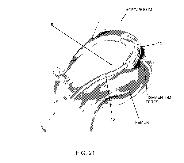
More particularly, in this form of the invention,
and looking next at Figs. 17-19, there is shown a
novel joint-spacing balloon catheter 5 formed in
accordance with the present invention. Novel
joint-spacing balloon catheter 5 generally comprises
an elongated shaft 10 having a balloon 15 disposed at
its distal end and a handle 20 disposed at its
proximal end.
Elongated shaft 10 is preferably flexible, and
preferably includes an internal stiffener 25 extending
along at least a portion of its length so as to
facilitate proper positioning of balloon 15 during
use. Internal stiffener 25 could comprise a round or
rectangular wire (e.g., such as shown in Fig. 19), and
be made out of a metal (e.g., stainless steel,
Nitinol, etc.) or plastic. If internal stiffener 25
comprises a rectangular wire, the short axis of the
wire can provide flexibility (e.g., to enable the
distal end of the joint-spacing balloon catheter 5 to
CA 02754905 2011-09-08
WO 2010/107949 PCT/US2010/027715
- 22 -
navigate around the curvature of the femoral head);
whereas, the long axis can provide stiffness to better
control the position of the balloon in the joint
space. If desired, elongated shaft 10 may also
include a rigid overshaft 30 adjacent to handle 20 so
as to further stiffen the proximal end of elongated
shaft 10, whereby to provide better control for the
positioning of balloon 15. Rigid overshaft 30 can be
a stainless steel tube. Rigid overshaft 30 can be
about 10 cm to about 30 cm in length, but is
preferably about 12.5 cm to about 22.5 cm in length.
A steering cable 35 is provided for steering the
direction of balloon 15. More particularly, steering
cable 35 extends through elongated shaft 10 between
the distal end of elongated shaft 10 and a steering
control mechanism 40 provided on handle 20. By
manipulating steering control mechanism 40, the user
is able to steer the direction of balloon 15, e.g., in
the manner shown in Fig. 18. More particularly,
steering control mechanism 40 and steering cable 35
are adapted to cause shaft 10 to arc. This arc can be
a radius of about 5 mm to about 10 cm, but is
preferably a radius of about 1 cm to about 5 cm.
Balloon 15 is preferably selectively
inflatable/deflatable via an inflation/deflation lumen
45 extending through elongated shaft 10 and handle 20.
An inflation/deflation control mechanism 50 is
interposed between inflation/deflation lumen 45 and a
CA 02754905 2011-09-08
WO 2010/107949 PCT/US2010/027715
- 23 -
supply port 55 which is connected to an appropriate
fluid reservoir (not shown). By manipulating
inflation/deflation control mechanism 50, the user is
able to inflate/deflate balloon 15 as desired.
Inflation/deflation control mechanism 50 may comprise
a stopcock, a valve, a pump and/or other fluid control
mechanisms. Balloon 15 preferably includes an
atraumatic tip 60 at its distal end.
On account of the foregoing, joint-spacing
balloon catheter 5 may have its balloon 15 set to its
deflated state via inflation/deflation control
mechanism 50, the deflated balloon may be advanced to
a remote site using handle 20 and steering control
mechanism 40, and then balloon catheter 5 may have its
balloon set to its inflated state by further
manipulating inflation/deflation control mechanism 50,
whereby to support tissue and maintain the distraction
of a joint, as will hereinafter be discussed in
detail.
Novel Method For Distracting A Joint
In another form of the present invention, there
is provided a novel method for distracting a joint,
preferably the hip joint, and preferably using novel
joint-spacing balloon catheter 5.
More particularly, in this form of the invention,
and looking now at Fig. 20, the hip joint is first
distracted using a standard leg distraction technique,
CA 02754905 2011-09-08
WO 2010/107949 PCT/US2010/027715
- 24 -
e.g., by positioning a perineal post between the
patient's legs, pulling on the distal end of the leg
with a substantial force, and then adducting the leg
so as to unseat the ball of the femur from the
acetabular cup, in the manner described above and
shown in Fig. 16.
Next, joint-spacing balloon catheter 5, with
balloon 15 set in its deflated state, is inserted into
the space created between the ball of the femur and
the acetabular cup. This may be done under direct
visualization (i.e., using an endoscope inserted into
the distracted joint), or under fluoroscopy, or both.
Then balloon 15 is inflated. See Fig. 21.
Next, the distal force which was previously
applied to the distal end of the leg is partially or
fully released. Release of the full distraction force
has the beneficial effect of completely eliminating
the tension load imposed on the intervening tissue,
whereas a partial release of the distraction force
only partially eliminates the tension load imposed on
the intervening tissue - however, even such partial
release of the distraction force can still
meaningfully reduce the tension load imposed on the
intervening tissue, and it provides a safeguard in the
event that balloon 15 should prematurely deflate,
e.g., mid-procedure. The aforementioned partial or
full release of the external distraction force allows
the ball of the femur to seat itself on the inflated
CA 02754905 2011-09-08
WO 2010/107949 PCT/US2010/027715
- 25 -
balloon, with the balloon acting as a spacer so as to
maintain a desired spacing between the ball of the
femur and the acetabular cup. Thus, joint distraction
is maintained even though a substantial distraction
force is no longer being applied to the distal end of
the leg. Since joint distraction can be reliably
maintained without the risk of damage to the
intervening tissue from a substantial
externally-applied distraction force, the traditional
concern to complete procedures in 90 minutes or less
is substantially diminished, and complications from
joint distraction are greatly reduced. This is a very
significant improvement over the prior art.
With the joint so distracted, the arthroscopic
surgery can then proceed in the normal fashion.
Significantly, and in accordance with another
novel aspect of the invention (see Fig. 22), the use
of joint-spacing balloon catheter 5 can enable the leg
to be manipulated while the joint is in a distracted
state. More particularly, it has been discovered
that, once balloon 15 has been inflated within the
joint and the pulling force applied to the distal end
of the leg has been partially or fully released, so
that the head of the femur is resting on the balloon,
the leg can be moved about (i.e., pivoted) on the
balloon. Manipulation can include flexion and
extension, adduction and abduction, as well as
internal and external rotation. See, for example,
CA 02754905 2011-09-08
WO 2010/107949 PCT/US2010/027715
- 26 -
Fig. 23. This manipulation of the leg while the joint
is in a distracted, balloon-supported state enables
more of the joint anatomy and pathology to be
visualized and accessed, for superior surgical
results. By contrast, a patient's leg cannot be
manipulated in this manner when the leg is being
distracted in a conventional manner, i.e., by a
pulling force applied to the distal end of the leg.
Therefore, procedures can be performed using the
present invention which cannot be performed using
conventional distraction techniques. This is a very
significant improvement over the prior art.
Additionally, some procedures which would
normally require the creation of an additional portal
to access pathology can be accomplished without the
creation of the additional portal, thereby reducing
the visible scar and potential morbidity of the
additional portal. This is also a significant
improvement over the prior art.
At the conclusion of the arthoscopic surgery, a
distal force is re-applied to the distal end of the
leg so as to take the load off the inflated balloon,
the balloon is deflated, and then the joint-spacing
balloon catheter is removed from the interior of the
joint.
Finally, the distal force applied to the distal
end of the leg is released, so as to allow the ball of
CA 02754905 2011-09-08
WO 2010/107949 PCT/US2010/027715
- 27 -
the femur to re-seat itself in its normal position
within the acetabular cup.
With respect to the foregoing method of the
present invention, it should be appreciated that
joint-spacing balloon catheter 5 can be specifically
located in the joint space so as to preferentially
bias the position of the femoral head relative to the
acetabulum when the pulling force on the distal end of
the leg is relaxed and the ball of the femur transfers
its load to (i.e., is seated on) the inflated balloon.
For example, positioning joint-spacing balloon
catheter 5 so that balloon 15 is more posterior in the
joint causes the femoral head to settle in a more
anterior position, which can improve visualization and
access to the posterior acetabular rim.
With respect to the foregoing method of the
present invention, it should also be appreciated that
joint-spacing balloon catheter 5 can be placed in the
joint space so as to provide better visualization and
access to the peripheral compartment of the hip.
Thus it will be seen that the present invention
provides a safe and simple way to significantly reduce
trauma to intervening tissue in the leg when
practicing leg distraction, since a substantial
distally-directed force only needs to be applied to
the distal end of the patient's leg long enough for
the deflated balloon to be positioned in the
distracted joint and for the balloon to thereafter be
CA 02754905 2011-09-08
WO 2010/107949 PCT/US2010/027715
- 28 -
inflated - the distally-directed distraction force
does not need to be maintained on the distal end of
the patient's leg during the surgery itself. As a
result, trauma to the intervening tissue is greatly
reduced, and the surgeon no longer needs to limit the
duration of distraction to 90 minutes or less in order
to avoid damage to the intervening tissue. This is a
very significant improvement over the prior art.
In addition, the use of the present invention
enables more of the joint anatomy and pathology to be
visualized and accessed, since supporting the ball of
the femur on an inflated balloon allows the initial
external distraction to be relaxed, and allows the leg
to be manipulated on the inflated balloon while the
joint is in a distracted state. By contrast, the leg
cannot be manipulated in this manner while the leg is
being distracted in a conventional manner, i.e., by a
pulling force applied to the distal end of the leg.
Therefore, arthroscopic procedures can be performed
using the present invention which cannot be performed
using conventional distraction techniques. This is a
very significant improvement over the prior art.
Additionally, some procedures which would
normally require the creation of an additional portal
to access pathology can be accomplished without the
creation of the additional portal, thereby reducing
the visible scar and potential morbidity of the
CA 02754905 2011-09-08
WO 2010/107949 PCT/US2010/027715
- 29 -
additional portal. This is also a significant
improvement over the prior art.
Further Details Of The Joint-Spacing Balloon Catheter
It will be appreciated that balloon 15 preferably
serves as a both a spacer and as a pivot support to
allow the manipulation of the femur while the joint is
distracted. Balloon 15 is constructed so as to be
atraumatic in order to avoid damaging the anatomy,
including the cartilage surfaces of the joint. At the
same time, and as will hereinafter be discussed in
further detail, balloon 15 may be appropriately
textured and/or sculpted in order to maintain its
position within the joint, preferentially to either
one of the acetabulum or femur, while still allowing
the opposing bone to move smoothly over the balloon
surface.
In one preferred form of the invention, elongated
shaft 10 has an outer diameter of about 0.040" (or
less) to about 0.250" (or more). An outer diameter of
approximately 0.120" to 0.200" is preferred for many
hip applications.
If desired, a retractable sheath (not shown) may
be provided over shaft 10 in order to cover balloon 15
prior to inflation.
And if desired, the distal end of shaft 10 can be
pre-shaped with a bend so as to give joint-spacing
CA 02754905 2011-09-08
WO 2010/107949 PCT/US2010/027715
- 30 -
balloon catheter 5 a directional bias at its distal
end.
Furthermore, if desired, and looking now at Figs.
23A-23D, an outer guiding member 57 may be provided
for directing joint-spacing balloon catheter 5 to a
location within the joint. More particularly, in this
form of the invention, outer guiding member 57
comprises a central lumen 58 sized to receive
joint-spacing balloon catheter 5; the outer guiding
member is advanced into position within the joint, and
then joint-spacing balloon catheter 5 is advanced down
the central lumen 58 of outer guiding member 57 so
that the distal end of joint-spacing balloon catheter
5 is properly disposed within the interior of the
joint.
More particularly, Fig. 23A is a schematic view
showing an outer guiding member 57 which may be used
to deploy joint-spacing balloon catheter 5 within the
joint. In many instances, the portal location does
not directly align with the entrance of the joint
space (i.e., with the acetabular rim region). Outer
guiding member 57 has a curve at its distal end which
can be aligned with the entrance of the joint space,
thus facilitating the delivery of joint-spacing
balloon catheter 5 into the interior of the joint
space. The joint-spacing balloon catheter 5 is
advanced through the central lumen 58 of outer guiding
member 57 and exits in a direction which better
CA 02754905 2011-09-08
WO 2010/107949 PCT/US2010/027715
- 31 -
facilitates navigating the distal end of the
joint-spacing balloon catheter around the femoral
head. The joint-spacing balloon catheter 5 could have
a pre-shaped distal end that further enables guidance
into the joint space. Alternatively, joint-spacing
balloon catheter 5 could be steerable as discussed
above. In practice, outer guiding member 57 is placed
such that the distal tip of the outer guiding member
is at or near the joint entrance (Figs. 23C and 23D).
Alternatively, the distal end of outer guiding member
57 can be placed within the joint space. The distal
tip of outer guiding member 57 is oriented in the
desired direction for proper placement of the
balloon. Joint-spacing balloon catheter 5 is advanced
through the central lumen 58 of outer guiding member
57 and into the joint space until balloon 15 is in the
desired location (the arrows in Figs. 23C and 23D
indicate direction of balloon catheter delivery). The
outer guiding member can be used to help adjust the
final balloon position. The outer guiding member 57
can be left in place during the procedure to help
tether the joint-spacing balloon catheter in position
within the joint. Additionally, outer guiding member
57 can provide a conduit to remove the joint-spacing
balloon catheter from the body.
In one preferred form of the invention, balloon
15 is preferably approximately 28 mm in diameter,
although it can also range from about 10 mm (or less)
CA 02754905 2011-09-08
WO 2010/107949 PCT/US2010/027715
- 32 -
in diameter to about 50 mm (or more) in diameter if
desired. Furthermore, the length of balloon 15 is
preferably approximately 50 mm, although it can also
range from about 10 mm (or less) in length to about 75
mm (or more) in length if desired. In this respect,
it will be appreciated that balloons of various sizes
may be used to address patients of different sizes,
variations in anatomy, and/or different pathologies.
Balloon 15 may be inflated with a pressure of up
to about 1000 psi, and is preferably inflated with a
pressure of up to about 200 psi, and is most
preferably inflated with a pressure of up to about 100
psi. In this respect it will be appreciated that it
is generally accepted that a force of about 50-80 lbs.
is sufficient to distract the hip joint. In order for
joint-spacing balloon catheter 5 to support this
force, it must provide sufficient pressure over a
sufficient surface area (force = pressure X area).
Although there are a number of different balloon sizes
and operating pressures which can be envisioned, there
are limitations on the balloon size and pressure to
consider. On the one hand, the balloon must be large
enough to cover a sufficient amount of cartilage such
that the pressure on the cartilage is lower than that
which would damage the cartilage. On the other hand,
the balloon must be small enough so as to permit
access to and visualization of the operative areas.
Hence, there is an optimal range of balloon size and
CA 02754905 2011-09-08
WO 2010/107949 PCT/US2010/027715
- 33 -
operating pressure, and this optimal range is
dependent on tissue dynamics.
In one preferred form of the invention, balloon
15 is fabricated so as to be semi-compliant, although
it can also be fabricated so as to be compliant or
non-compliant if desired. Examples of semi-compliant
balloon materials are polyurethane, nylon and
polyether block amide (PEBA). An example of a
compliant balloon material is silicone rubber. An
example of a non-compliant balloon material is
polyethylene terapthalate (PET). A compliant or
semi-compliant balloon is generally preferred since it
will deform under load to the shape of the surface
which the balloon is contacting in order to help
distribute load onto that surface. A semi-compliant
balloon is generally most preferred since it will
retain some aspects of its pre-load shape even when
under load, which can be helpful in directing or
maintaining bone positioning, particularly when the
leg is being manipulated while in a distracted state.
The thickness of the balloon material is preferably in
the range of about 0.001" to about 0.020", and is most
preferably between about 0.002" and about 0.012". The
durometer of the balloon material is preferably in the
range of about 30 Shore A to about 85 Shore D, and is
most preferably between about 40 Shore D and about
85 Shore D.
CA 02754905 2011-09-08
WO 2010/107949 PCT/US2010/027715
- 34 -
If desired, the surfaces of balloon 15 can be
textured (e.g., with dimples, ridges, etc.) or covered
with another material (e.g., a coating or covering) so
as to prevent slippage of the balloon along cartilage
when the balloon is being used to support a joint. At
the same time, this surface texture or non-slip
covering is configured so as to engage the cartilage
without causing cartilage damage. In one preferred
form of the invention, only a portion of the outer
surface of the balloon is textured or covered with a
non-slip material. For example, the portion of the
balloon which faces the acetabulum could be textured
or covered with a non-slip material, but the portion
of the balloon which faces the femoral head could be
non-textured or non-covered, so as to keep the surface
facing the acetabulum from slipping while allowing the
surface facing the femoral head to slide relative to
the femoral head. In another preferred form of the
invention, a majority of the balloon surface is
textured or covered with a non-slip material. In yet
another preferred form of the invention, two or more
different textures or non-slip coverings are provided
on the outer surface of the balloon, e.g., depending
on the particular cartilage surface which they may
engage.
In yet another embodiment of the invention, the
balloon is covered with a low friction material which
enables slippage of the joint surface on the balloon.
CA 02754905 2011-09-08
WO 2010/107949 PCT/US2010/027715
- 35 -
The low friction material may cover some or all of the
balloon surface.
The balloon may comprise both low slippage and
low friction coverings if desired.
Furthermore, if desired, fluoroscopic markings
can be incorporated into or disposed on elongated
shaft 10, or incorporated into or disposed on balloon
15, or incorporated into or disposed on another part
of joint-spacing balloon catheter 5, so as to render
the apparatus visible under X-ray. Such fluoroscopic
markings may comprise radiopaque ink applied to the
apparatus, radiopaque bands applied to the apparatus,
radiopaque material incorporated in the construction
of the apparatus, and/or a radiopaque fluid used to
inflate the balloon (such as a contrast agent). By
way of example but not limitation, a radiopaque band
material could comprise platinum. By way of further
example but not limitation, a radiopaque fluid could
comprise a contrast agent such as Dodecafluoropentane.
In one preferred form of the invention, balloon
15 is preferably inflated with a liquid medium, e.g.,
saline; however, it could also be inflated with a
gaseous medium, e.g., air. Among other things, the
balloon can be inflated with a high viscosity fluid.
This latter construction may be beneficial in the
event of a balloon puncture as it would slow the pace
of balloon deflation. If desired, a fluid could be
used which changes viscosity when subject to changes
CA 02754905 2011-09-08
WO 2010/107949 PCT/US2010/027715
- 36 -
in temperature, electrical charge, magnetic field, or
other means. Alternatively, the balloon can be filled
with a compound which increases in viscosity when
exposed to saline. This latter construction can be
advantageous in certain circumstances, e.g., during a
balloon puncture, the escaping fluid would react to
the saline present in the joint and could at least
partially seal the puncture hole in the balloon.
Where balloon 15 is inflated with a gaseous
medium, and that gaseous medium is air,
inflation/deflation control mechanism 50 may comprise
a pump, and supply port 55 may be open to the
atmosphere.
In one aspect of the invention, and looking now
at Figs. 24-28, joint-spacing balloon catheter 5
further comprises one or more expandable elements 60
in addition to balloon 15. These expandable elements
60 can be another balloon, a collapsible braid, and/or
some other structure which can expand when desired to
a larger dimension. Expandable element 60 can be used
to releasably secure joint-spacing balloon catheter 5
to the joint capsule. In one embodiment, and as shown
in Fig. 24, an expandable element 60 is located at the
distal end of the joint-spacing balloon catheter.
This expandable element 60 is expanded once the distal
end of the balloon catheter (and the expandable
element 60) has passed through the capsule 62 at the
far side of the joint, so that the expandable element
CA 02754905 2011-09-08
WO 2010/107949 PCT/US2010/027715
- 37 -
is deployed on the far side of the capsule, whereby to
stabilize balloon 15 within the joint. See Fig. 25.
In another embodiment, a second expandable element 60
is expanded adjacent to the internal surface of the
far capsule, as shown in Fig. 26, so that the far side
of the capsule is sandwiched between the two
expandable elements 60, whereby to further stabilize
balloon 15 within the joint. In this respect it
should be appreciated that the two expandable elements
60 may or may not be expanded simultaneously. In yet
another embodiment, and looking now at Fig. 27, one or
more expandable elements 60 are disposed proximal to
the balloon, to tether the joint-spacing balloon
catheter to capsule 62 at the proximal portion of the
joint, such as is shown in Fig. 28.
In another embodiment (Fig. 28A), a second
cannula 63 is used to secure the distal end of
joint-spacing balloon catheter 5 relative to the
anatomy. More particularly, the distal tip of the
joint-spacing balloon catheter, or a flexible element
64 which extends from the distal end of the
joint-spacing balloon catheter (e.g., a guidewire), is
passed into the tip of the second cannula 63. The
flexible element could be a wire, a suture, a ribbon,
a catheter, a braid, or some other construction which
is flexible or semi-flexible. The flexible element 64
can be received within the second cannula or, if
desired, gripped within the second cannula. A
CA 02754905 2011-09-08
WO 2010/107949 PCT/US2010/027715
- 38 -
gripping feature (not shown) could be provided in the
second cannula to achieve this. Alternatively, the
flexible element 64 could pass entirely through the
second cannula. In any case, this construction
results in the tip of joint-spacing balloon catheter 5
being stabilized in position by the second cannula 63.
Additionally, and looking now at Fig. 29, another
lumen 65 can be provided for a guidewire, obturator,
light fiber, electrical wire, or the like, or as an
additional inflation lumen, etc. And, as shown in
Fig. 30, further lumens 70 can be provided for working
instruments, etc. If desired, a pre-shaped guidewire
or obturator can be placed through one of the lumens
of elongated shaft 10 in order to bias the tip
direction of the joint-spacing balloon catheter 5 as
the joint-spacing balloon catheter is advanced over
the pre-shaped guidewire or obturator. Alternatively,
a second steerable wire can be placed through one of
the lumens, so as to enable steering of the balloon
catheter in a second direction.
To improve resistance to kinking, or to provide
the shaft with the desired stiffness and torsional
characteristics, a braid or coil 71 (Fig. 30) could be
incorporated into the catheter. The braid or coil
could comprise a stainless steel wire, a Nitinol wire,
etc. Braid or coil 71 could be incorporated at any
section of joint-spacing balloon catheter 5, but is
CA 02754905 2011-09-08
WO 2010/107949 PCT/US2010/027715
- 39 -
preferably located in at least the flexible section of
the catheter.
In Figs. 17-19, balloon 15 is shown with a
generally cylindrical configuration. However, if
desired, balloon 15 can have different configurations.
Thus, for example, and looking now at Figs. 31 and 32,
balloon 15 can comprise a pair of opposing flat
surfaces 72; or, and looking now at Figs. 33 and 34,
balloon 15 can have an hourglass shape which includes
an intermediate section 73 of reduced diameter; or,
and looking now at Fig. 35, balloon 15 can have a
generally hourglass shape with a pair of opposing flat
surfaces 72. The aforementioned hourglass shapes,
although depicted symmetrical, can also be asymmetric.
For example, one end of the hourglass-shaped balloon
may be of a larger dimension (length, diameter, etc.)
than the other end of the hourglass-shaped balloon.
Balloon 15 may also be in the form of an arc or
other curvature (i.e., a geometry where one side has a
greater curvature than the other side), or some other
shape (e.g., U-shaped), so as to fit around the
ligamentum teres. See Fig. 36. Additionally, balloon
15 could have the shape of a torus, so as to provide a
seat for the ball of the femur. See Figs. 37 and 38.
It is also possible to provide joint-spacing
balloon catheter 5 with more than one balloon 15.
Where more than one balloon is provided, the balloons
can be disposed in series (i.e., end-to-end, such as
CA 02754905 2011-09-08
WO 2010/107949 PCT/US2010/027715
- 40 -
is shown in Fig. 39), or in parallel (such as shown in
Figs. 40 and 41), with or without complementary
geometries (such as shown in Figs. 42 and 43), or
combinations of such geometries (such as shown in Fig.
44), or toroidal (such as is shown in Fig. 45), etc.
The shafts of the multiple balloons may be separated
at their distal end (such as is shown in Fig. 40) or
may be joined at their distal ends (such as is shown
in Fig. 41). Multiple balloons may be of the same
construction, or they may be of different
constructions. For example, multiple balloons may be
of different sizes, shapes, materials, compliances,
coatings, surface textures, coverings, colors, and/or
other aspects of construction. Additionally, the
multiple balloons may be inflated to different
pressures and/or volumes.
These multiple balloons 15 can also be disposed
in a mutually-supporting configuration, as shown in
Figs. 46-52. By arranging the multiple balloons 15 in
a mutually-supporting configuration, the multiple
balloons 15 may better conform to the acetabulum and
femoral surfaces, which would be beneficial in order
to reduce pressure on the cartilage and/or to help
maintain the balloons in position within the joint
space (i.e., to prevent slipping). In this form of
the invention, a balloon catheter 5 could have an
assembly of balloons 15 that would collectively act as
a compliant or semi-compliant device even though the
CA 02754905 2011-09-08
WO 2010/107949 PCT/US2010/027715
- 41 -
individual balloons are non-compliant, or vice versa.
An additional benefit of arranging the multiple
balloons 15 in a mutually-supporting configuration is
that if one of the balloons deflates, the other
balloons can still maintain a substantial portion of
the joint space. In one preferred construction, the
balloons 15 can slide against each other to spread
out, e.g., to spread out in a lateral direction.
Where joint-spacing balloon catheter 5 comprises
multiple balloons 15, preferably, a separate
inflation/deflation lumen is provided for each
balloon, so that each balloon can be separately
inflated or deflated, although a single
inflation/deflation lumen could be used to
simultaneously inflate/deflate more than one balloon.
By permitting each balloon of a group of balloons to
be selectively inflated, the surgeon can influence the
manner in which the ball of the femur is supported
relative to the acetabular cup. In one preferred
manner of use, each of the balloons may be inflated to
a different volume (and/or pressure) than others of
the balloons. This approach can be used to impart a
specific shape to the overall balloon structure.
Also, some of the balloons 15 can be made compliant,
and others non-compliant, so as to achieve a desired
pressure distribution and/or shape for the overall
balloon structure.
CA 02754905 2011-09-08
WO 2010/107949 PCT/US2010/027715
- 42 -
It is also possible to provide each of the
balloons 15 with a plurality of separate internal
chambers 75 (Figs. 53-55). Preferably each of these
separate chambers 75 can be selectively inflated so as
to influence the manner in which the ball of the femur
is supported relative to the acetabular cup. Thus, in
this sort of construction, selective inflation of the
various chambers can be used to adjust the position of
the ball of the femur within the acetabular cup when
the pulling force on the distal end of the leg is
relaxed. The use of multiple chambers may also
provide a safer design. More particularly, in the
event that one of the chambers 75 is punctured during
a procedure, the use of multiple chambers 75 may
permit some joint distraction to be maintained, thus
reducing the chances that, for example, an instrument
will be wedged between the femoral head and
acetabulum.
If desired, balloons 15 can be formed so as to be
puncture resistant in order to minimize the
possibility of inadvertently deflating the balloon,
e.g., with an errant surgical instrument. To this
end, and looking now at Fig. 56-59, a balloon 15 can
embed, or sandwich, a puncture-resistant structure 80
(e.g., a coil or mesh or strand or braid formed out of
Nitinol, or stainless steel, or a polymer, etc.)
between two layers of material (preferably a
non-abrasive elastomer). Alternatively, the
CA 02754905 2011-09-08
WO 2010/107949 PCT/US2010/027715
- 43 -
puncture-resistant structure 80 could be placed on one
side of, or embedded within, a single sheet of
material, such as is shown in Fig. 60. This
puncture-resistant structure 80 may be a separate
element added to the wall of the balloon or a coating
applied to the wall of the balloon. The puncture-
resistant structure 80 may also be a layer of material
within the side wall of the balloon; for example, the
outer layer may be a puncture-resilient material (such
as polyurethane) to enhance puncture resistance, while
the inner layer material maintains the balloon
pressure (such as PET). In one preferred
construction, puncture-resistant structure 80 covers a
substantial portion of the balloon surface. In
another preferred construction, the puncture-resistant
structure 80 covers a smaller portion of the balloon
surface; in this instance, the surface incorporating
the puncture-resistant structure 80 is disposed on the
side of the balloon where instruments are used (which
could puncture the balloon).
Furthermore, if desired, and looking now at Figs.
60A-60D, the distal end of joint-spacing balloon
catheter 5 could include a shroud 82 disposed over
balloon 15. Shroud 82 may be formed out of a
puncture-resistant material so as to protect balloon
15 from inadvertent puncture. Additionally, and/or
alternatively, shroud 82 could be formed so as to
define the volume created within the joint when
CA 02754905 2011-09-08
WO 2010/107949 PCT/US2010/027715
- 44 -
balloon 15 is inflated. This construction can be
advantageous where balloon 15 is formed out of a
compliant material and it is desired to control the
manner in which space is created within the joint,
i.e., by using a non-compliant or semi-compliant
shroud 82. Additionally, and/or alternatively, shroud
82 could be formed out of a material which provides
slippage (e.g., it can be formed out of ePTFE). This
can be beneficial in a number of ways. First, it can
facilitate easier delivery of the balloon into the
joint, including passage through the entry cannula.
In a similar way, shroud 82 can also facilitate easier
removal of the joint-spacing balloon catheter from the
joint, including through the entry cannula. By having
enhanced slippage properties, shroud 82 can also
facilitate joint manipulation on the balloon. The
shroud's geometry (e.g., tapered ends) can also
facilitate ease of delivering and removing the
joint-spacing balloon catheter to and from the joint
space; this may be particularly beneficial if the
balloon catheter goes through an entry cannula.
Alternatively, the shroud 82 could be formed out of a
material which prevents slippage on the joint surface
(e.g. a low durometer elastomer). This can be
beneficial to enable the balloon to remain stationary
on the joint surfaces once it has been placed in the
joint space. Additionally, and/or alternatively,
shroud 82 can be constructed so as to provide better
CA 02754905 2011-09-08
WO 2010/107949 PCT/US2010/027715
- 45 -
endoscopic visualization of the balloon; for example,
shroud 82 can be an opaque color.
Alternatively, and looking now at Figs. 61-63, a
shield 85 could be placed alongside balloon 15 to
protect the balloon from being punctured from that
direction. Shield 85 is preferably introduced into
the joint after the balloon has been inserted and
inflated, but shield 85 could also be inserted into
the joint prior to that if desired. Shield 85 could
be made out of a material similar to the
puncture-resistant structure 80 described above.
Alternatively, and looking now at Figs. 64-68, a
balloon-within-a-balloon configuration can be used to
provide one or more secondary "fail-safe" (or
"safety") balloons 90 within the primary balloon 15 -
such a construction can minimize the risk that joint
distraction will be lost in the event that the primary
balloon 15 is inadvertently deflated, e.g., by an
accidental puncture. If desired, the inner balloon 90
can be made of a different material than the outer
balloon 15. In one preferred construction, inner
balloon 90 is non-compliant and outer balloon 15 is
semi-compliant. The inner and outer balloons could
also have different wall thicknesses, geometries, or
other aspects of construction as discussed above.
Alternatively, a different type of secondary
structure can be deployed in balloon 15 in order to
prevent balloon 15 from completely collapsing in the
CA 02754905 2011-09-08
WO 2010/107949 PCT/US2010/027715
- 46 -
event that it is punctured. In one embodiment, and
looking now at Fig. 69, a wire 95 is delivered into
the interior of the balloon and fills up a portion of
the internal balloon volume; in the event that the
balloon is punctured, wire 95 provides support to
prevent the joint space from collapsing. Wire 95 is
preferably made of Nitinol, but could also be formed
out of another metal or polymer if desired. In
another embodiment, and looking now at Fig. 70, a wire
100 is delivered across the length of the balloon and
set in a bowed configuration. The bowed wire 100
provides mechanical support in the event the balloon
is punctured. In Fig. 71, an exemplary mechanical
scaffold 105 is shown deployed in the interior of the
balloon so as to provide a safety mechanical support.
In Fig. 72, an expandable foam 110 is deployed within
the interior of the balloon; foam 110 expands to fill
some or most of the internal balloon space. In one
embodiment, expandable foam 110 absorbs fluid and will
therefore absorb saline within the balloon. This
construction can reduce the speed at which a punctured
balloon will deflate.
In yet another embodiment (Figs. 73 and 74), the
balloon is filled with beads 115. Beads 115 could be
absorbent polymer or foam, or non-absorbent. As shown
in Figs. 75-77, if beads 115 are non-absorbent, the
balloon's inflation fluid can be evacuated from the
balloon after beads 115 have been introduced into the
CA 02754905 2011-09-08
WO 2010/107949 PCT/US2010/027715
- 47 -
inflated balloon, leaving a compact "bean bag"
structure to maintain the joint space. As shown in
Fig. 78, beads 115 are preferably delivered into the
interior of the balloon in a strand configuration,
i.e., mounted on a filament 116. This approach has
the additional advantage that, in the event that the
balloon should lose its integrity, beads 115 can be
safely removed without leaving any beads in the hip
joint, i.e., by pulling proximally on filament 116.
If desired, beads 115 can be disposed between a
primary outer balloon 15 and secondary inner balloon
90.
If desired, joint-spacing balloon catheter 5 can
include pressure regulation, e.g., a release valve
(not shown) to ensure that a balloon is not inflated
beyond a maximum level, or an alarm or other alert
(not shown) to advise the user that a balloon has been
inflated beyond a pre-determined level. This can be
important to avoid damage to the patient's tissue or
to reduce the risk of inadvertent balloon rupture.
Furthermore, a check valve (not shown) may be
installed on the inflation port(s) 55 to enable
joint-spacing balloon catheter 15 to be disconnected
from the fluid reservoir while maintaining pressure in
balloon 15.
It is also possible to place markings (e.g.,
longitudinal lines) along the body of balloon 15, or
to color the balloon material, so as to improve
CA 02754905 2011-09-08
WO 2010/107949 PCT/US2010/027715
- 48 -
endoscopic visualization of the balloon, including to
show the degree of balloon inflation. Alternatively,
the fluid used to inflate the balloon could be
colored, or the balloon surface could have texture, in
order to aid visualization of the balloon.
Alternatively, a transparent, thick-walled balloon 15
can be used to increase visualization of the balloon
by increasing the refraction of light, which will make
the balloon foggy in appearance. Alternatively, a
coating could be applied to the balloon material which
improves the endoscopic visualization of the balloon.
Alternatively, a second balloon or an expandable
extrusion could be placed over the primary balloon so
as to improve endoscopic visualization. The second
balloon and/or expandable extrusion may be colored for
improving endoscopic visualization. This
configuration can also add to the puncture resistance
of the primary balloon and assist in the delivery and
retrieval of the primary balloon.
The joint-spacing balloon catheter 5 may also
comprise a sensor (not shown). The sensor can measure
the temperature of the surrounding tissue or fluid in
the joint (e.g., the sensor may be a temperature
sensor). The sensor may also detect characteristics
of the adjacent cartilage, such as thickness, density,
and/or quality (e.g., the sensor may be an ultrasound
device, etc.). The sensor could be located on shaft
CA 02754905 2011-09-08
WO 2010/107949 PCT/US2010/027715
- 49 -
or on balloon 15, or on another portion of joint-
spacing balloon catheter 5.
External Distraction Of The Limb
5 In the foregoing description, the external
distraction of the limb is generally discussed in the
context of applying a distally-directed distraction
force to the distal end of the leg. However, it
should be appreciated that the distally-directed
10 distraction force may be applied to another portion of
the leg, e.g., to an intermediate portion of the leg,
such as at or about the knee. Thus, as used herein,
the term "distal end of the leg" is meant to include
substantially any portion of the leg which is distal
to the ball of the femur, such that by applying the
external distraction force to the leg, a tension load
is imposed on the intervening tissue. Furthermore, as
used herein, the term "intervening tissue" is intended
to mean the tissue which is interposed between the
location where the external distraction force is
applied to the leg and the ball of the femur.
Inflatable Perineal Post
The present invention also preferably comprises
the provision and use of a novel inflatable perineal
post for facilitating joint distraction.
More particularly, and looking now at Figs. 79
and 80, there is shown an inflatable perineal post 120
CA 02754905 2011-09-08
WO 2010/107949 PCT/US2010/027715
- 50 -
which generally comprises a relatively narrow,
substantially rigid inner core 125 surrounded by a
relatively wide, substantially soft inflatable balloon
130. In an alternative embodiment as is shown in
Figs. 81 and 82, inflatable perineal post 120
comprises a soft inflatable balloon 130 is supported
on one or more sides by a substantially rigid support
structure 135. Such a non-cylindrical construction,
with inflation being directed along selected
directions, can be highly beneficial, since it can
reduce engagement of the non-working portions of the
perineal post with patient anatomy (e.g., the
genitalia). Still other post shapes and
configurations can be envisioned by one skilled in the
art in view of the present disclosure.
The inflatable balloon 130 of the inflatable
perineal post 120 is preferably constructed out of a
semi-compliant material, but it could also be
compliant or non-compliant. The inflatable balloon
130 of the inflatable perineal post 120 may involve a
covering (not shown) for contact with the patient;
this covering may be a non-slip material. The
inflatable balloon 130 is preferably inflated with a
manual or electric pump. The inflatable perineal post
120 could include a read-out panel displaying the
balloon pressure.
The inflatable perineal post 120 may also
comprise physiologic sensors (not shown) for
CA 02754905 2011-09-08
WO 2010/107949 PCT/US2010/027715
- 51 -
monitoring parameters such as patient skin temperature
and blood flow. Such parameters may be reflective of
patient conditions of interest to the surgeon, e.g., a
falling patient skin temperature is frequently
indicative of reduced blood flow. These physiologic
sensors could be incorporated into the surface of the
balloon, or they could be separate sensors which are
included as part of a kit provided with the inflatable
perineal post. The physiologic sensors are adapted to
be connected to a monitor so as to provide read-outs
on the monitor.
In use, the deflated perineal post balloon is
positioned between the patient's legs, the joint is
distracted by pulling on the distal end of the leg so
that the ball of the femur is spaced from the
acetabular cup, the perineal post balloon is inflated,
a joint-spacing balloon catheter 5 is inserted into
the distracted joint, the balloon 15 is inflated, the
force applied to the distal end of the leg is relaxed
so that the ball of the femur settles back down onto
the one or more inflated balloons 15, and then the
perineal post balloon 130 is at least partially
deflated. At this point the arthroscopic surgery can
be conducted without trauma to the patient's tissue,
due to either the distal distraction of the leg or due
to engagement of the perineal post with the tissue of
the patient. At the conclusion of the surgery, the
CA 02754905 2011-09-08
WO 2010/107949 PCT/US2010/027715
- 52 -
distal end of the leg is pulled distally again, the
perineal post balloon 130 is inflated, the
joint-spacing balloon 15 is deflated, the
joint-spacing balloon catheter 5 is removed from the
joint, and the joint is reduced. Alternatively, the
perineal post balloon could be inflated prior to
pulling on the distal end of the leg. Or,
alternatively, the perineal post balloon 130 could be
deflated prior to withdrawal of the force being
applied to the distal end of the leg. In some cases,
only one of either (i) pulling on the leg, or (ii)
inflating of the perineal post is performed in order
to remove or re-position the joint-spacing balloon.
If desired the inflatable perineal post 120 may
be used to replace a standard perineal post, and is
used in conjunction with a standard traction table; in
other words, in this form of the invention, the
inflatable perineal post 120 is not used in
conjunction with a joint-spacing balloon catheter 5.
One Preferred Form Of The Invention
In one preferred form of the present invention,
the aforementioned novel method for distracting the
joint is implemented using the aforementioned novel
joint-spacing balloon catheter 5 and the
aforementioned inflatable perineal post 120.
More particularly, in this form of the invention,
the hip joint is first distracted by pulling on the
CA 02754905 2011-09-08
WO 2010/107949 PCT/US2010/027715
- 53 -
distal end of the leg just above the ankle, and then
inflating the inflatable perineal post, where the
perineal post is positioned between the patient's
legs. The leg may be adducted so as to lever the
femur laterally. Alternatively, the inflatable
perineal post could be inflated prior to the distal
end of the leg being pulled distally.
Next, the surgeon identifies a portal location
for joint-spacing balloon catheter delivery. Then a
needle is placed into the joint, the stylet is
removed, a guidewire is delivered through the needle,
and then the needle is removed. The guidewire can be
placed in the desired delivery path of the
joint-spacing balloon catheter 5.
An arthroscopic cannula or outer guiding member
may then be emplaced if desired; in this instance, the
guidewire may be removed if desired.
Next, a joint-spacing balloon catheter 5 of the
appropriate size is selected from a kit providing a
range of differently-sized joint-spacing balloon
catheters. Then the joint-spacing balloon catheter 5
is delivered over the guidewire (either percutaneously
or through a cannula) to the target site between the
femoral head and the acetabulum. The joint-spacing
balloon catheter 5 may be rotated as appropriate if
there is asymmetry in the balloon's shape.
Alternatively, the joint-spacing balloon catheter 5
CA 02754905 2011-09-08
WO 2010/107949 PCT/US2010/027715
- 54 -
may be delivered through a cannula without the use of
a guidewire.
Next, a syringe (or other inflation device) is
secured to the joint-spacing balloon catheter 5, and
the balloon 15 is inflated to the desired pressure
and/or size. If there is more than one balloon 15,
the additional balloon(s) can be inflated. If the
additional balloon(s) are used to affect the direction
of joint spacing, the pressure and/or size of each
balloon is adjusted so as to achieve the desired joint
spacing direction.
Once the balloon has been inflated to the desired
pressure and/or size, the distraction force applied to
the leg is at least partially removed, allowing the
head of the femur to rest on the inflated balloon
(which is itself supported by the acetabulum).
Additionally, the inflatable perineal post 120 is
deflated as appropriate; this could occur before the
leg distraction force is released.
The balloon 15 can be re-positioned by re-
applying distraction force to the leg and/or re-
inflating the inflatable perineal post 120, deflating
balloon 15 and re-positioning the joint-spacing
balloon catheter 5, re-inflating the balloon of the
joint-spacing balloon catheter, then releasing the leg
distraction and/or deflating the inflatable perineal
post. The balloon 15 may be placed in a location
which directs the distraction in a preferred
CA 02754905 2011-09-08
WO 2010/107949 PCT/US2010/027715
- 55 -
direction. Alternatively, where the joint-spacing
balloon catheter comprises a plurality of balloons,
the balloons may be inflated to different sizes and/or
pressures in order to direct the joint distraction in
a preferred direction.
With the balloon maintaining the joint
distraction, the leg may be manipulated (i.e. rotated,
flexed, etc.) in order to visualize and access
pathology through the established portals.
Then the arthroscopic surgery is conducted. The
leg may be manipulated a number of times through the
procedure in order to visualize, access and treat
pathology.
At the conclusion of the arthroscopic surgery,
the hip joint is distracted again, e.g., by pulling on
the distal end of the leg just above the ankle, so as
to lift the head of the femur off the balloon. The
perineal post balloon may be inflated. The balloon 15
of the joint-spacing balloon catheter is deflated and
the joint-spacing balloon catheter is removed.
Thereafter, the distraction force applied to the leg
may be removed, allowing the head of the femur to
settle back on the acetabulum.
In another form of the invention, while the
distal end of the leg is held stationary, the perineal
post 120 is inflated to break the suction seal of the
hip joint and enable the joint-spacing balloon
catheter 5 to be placed in the joint and inflated. In
CA 02754905 2011-09-08
WO 2010/107949 PCT/US2010/027715
- 56 -
this case, no pulling on the leg is performed. This
would have the benefit of eliminating a piece of
equipment from the surgery and reducing the
corresponding surgical time associated with using that
equipment.
In yet another form of the invention, the
joint-spacing balloon catheter 5 can perform some or
all of the joint distraction. In one embodiment, a
first joint-spacing balloon catheter 5 is placed
adjacent to the femoral head and the balloon is
inflated. The leg is then manipulated in abduction or
adduction (depending on balloon location), thus
levering the femoral neck against the balloon. This
levering creates a gap at the acetabular rim. A
second joint-spacing balloon catheter 5 is then
inserted into the gap and delivered into the joint
space (the space between the femoral head and the
acetabulum). The balloon of the second joint-spacing
balloon catheter is then inflated and distracts the
joint; that is, opens up the joint space. In one
embodiment, the first balloon is placed on the
lateral/superior aspect of the femoral neck. Once the
second balloon is inflated, the first balloon can be
deflated and withdrawn. The first balloon may be of a
different size and shape as the second balloon. It
also may be inflated to a different pressure.
Kits
CA 02754905 2011-09-08
WO 2010/107949 PCT/US2010/027715
- 57 -
The joint-spacing balloon catheter 5 and the
inflatable perineal post 120 may be offered as part of
a single kit. A guidewire or obturator, outer guiding
member and a balloon inflation device may additionally
be provided.
Use Of The Present Invention
For Other Applications
It should be appreciated that the present
invention may be used for distracting the hip joint in
an open, more invasive procedure. The present
invention can also be used in hip joint pathologies
where joint distraction is not needed but space
creation is needed, e.g., to visualize and/or to
address pathologies in the peripheral compartment or
pathologies in the peritrochanteric space.
Additionally, the present invention may be used for
distracting joints other than the hip joint (e.g., it
may be used to distract the shoulder joint).
Modifications Of The Preferred Embodiments
It should be understood that many additional
changes in the details, materials, steps and
arrangements of parts, which have been herein
described and illustrated in order to explain the
nature of the present invention, may be made by those
skilled in the art while still remaining within the
principles and scope of the invention.