Note: Descriptions are shown in the official language in which they were submitted.
CA 02755277 2011-09-13
WO 2010/105017 PCT/US2010/026918
1
PROCESS FOR MAKING AN EMBOSSED WEB
FIELD OF THE INVENTION
The invention relates to a process for making an embossed web comprising a
plurality of
discrete extended elements.
BACKGROUND OF THE INVENTION
Web materials, such as thermoplastic films, have a variety of uses including
component
materials of absorbent articles (such as topsheets and backsheets), packaging
(such as flow wrap,
shrink wrap, and polybags), trash bags, food wrap, dental floss, wipes,
electronic components,
and the like. For many of these uses of web materials, it can be beneficial
for the web material to
have a textured surface which can provide the surface of the web material with
a desirable feel,
visual impression, and/or audible impression.
Polymeric webs exhibiting a soft and silky tactile impression can be made via
a vacuum
forming process or a hydroforming process. With a typical vacuum forming
process, a precursor
web is heated and placed over a forming structure. Then a vacuum forces the
precursor web to
conform to the texture of the forming structure. The resulting polymeric web
has texture that can
provide a soft and silky tactile impression, depending upon the texture of the
forming structure
and degree of conformation. While a vacuum forming process can be suitable for
making a soft
and silky polymeric web, a vacuum forming process is typically limited with
respect to the
amount of pressure capable of being exerted onto a precursor web. As a result,
it is usually
required to heat a precursor film to significantly soften or melt the
precursor film prior to
placement on the forming structure in order to vacuum form the precursor film
to the forming
structure. A vacuum forming process is therefore an inefficient process in
terms of how fast the
process can be performed due to the heating step and the limited pressures
generated by the
process.
With a typical hydroforming process, a precursor web is placed over a forming
structure
and high pressure and high temperature water jets force the precursor web to
conform to the
texture of the forming structure. The resulting polymeric web can have texture
that can provide a
soft and silky tactile impression, depending upon the texture of the forming
structure. A
hydroforming process, although capable of producing soft and silky polymeric
webs, is typically
a costly and inefficient process involving the use of high pressure and high
temperature water jets
and subsequent drying steps, including dewatering steps.
CA 02755277 2011-09-13
WO 2010/105017 PCT/US2010/026918
2
Embossing is a process that typically involves the act of mechanically working
a substrate
to cause the substrate to conform under pressure to the depths and contours of
a pattern engraved
or otherwise formed on an embossing roll. It is widely used in the production
of consumer goods.
Manufacturers use the embossing process to impart a texture or relief pattern
into products made
of textiles, paper, synthetic materials, plastic materials, metals, and wood.
Embossing processes have been used to provide texture to polymeric films.
However,
such embossing processes typically require extruding a molten resin onto a
forming structure or
heating a precursor web before placement onto a forming structure and then
embossing to
produce an embossed web. The embossed web is then cooled, typically by cooling
the embossing
rolls or plates used to emboss the heated precursor web or molten resin. The
cooling step is often
utilized to set the texture in the embossed web. However, these heating and
cooling steps add
undesirable cost and inefficiency, as well as complexity, to the process. In
addition, such
embossing processes typically involve relatively large dwell times, which can
result in slow,
inefficient processes.
It is also typically difficult to impart relatively small scale texture to
precursor webs using
conventional embossing processes. Furthermore, typical embossing processes
tend to produce
embossed webs having relatively uniform thickness throughout the web.
For example, U.S. Patent No. 5,972,280 discloses an embossing process
utilizing a hot
engraved surface of an embossing roll and static pressure applied within a
chamber to heat a web
and deform it over the surface of the embossed roll. This process uses
elevated temperatures,
which are typically above the softening temperature of the web, and relatively
low pressures of
about 0.007 MPa to about 0.7 MPa. As a result, the embossed pattern is formed
as indentations
disposed on only a single surface of the web, without affecting the opposite
surface of the web.
Despite the knowledge in the art, there remains a desire to develop a more
efficient
process for making embossed webs that have desirable feel, visual impression,
and/or audible
impression, especially embossed webs exhibiting thinning in desirable areas of
the embossed
web. In certain aspects, a desired process is efficient with respect to the
energy and resources
required by the process. In certain aspects, a desired process is capable of
running at high speeds.
In certain aspects, a desired process is capable of running at relatively low
temperatures, such as
ambient temperature.
CA 02755277 2011-09-13
3
SUMMARY OF THE INVENTION
In one embodiment, a process for making an embossed web includes feeding a
precursor
web between a static gas pressure plenum and a forming structure having a
plurality of discrete
protruded elements. The method further includes applying pressure from the
static gas pressure
plenum against the precursor web opposite the forming structure thereby
creating a differential
pressure across the precursor web sufficient to conform the precursor web to
the discrete
protruded elements of the forming structure to form the embossed web
comprising a plurality of
discrete extended elements having open proximal ends.
In one embodiment the discrete protruded elements have a height of at least
substantially equal to a thickness of the precursor web. Additional features
of the invention
may become apparent to those skilled in the art from a review of the following
detail
description, taken in conjunction with the drawings, the examples, and the
appended claims.
BRIEF DESCRIPTION OF THE DRAWINGS
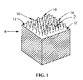
Figure 1 is a perspective view of a portion of a forming structure in
accordance with an
embodiment of the disclosure;
Figure 2 is an enlarged perspective view of a portion of the forming structure
shown in
FIG. 1;
Figure 3 is a top view of a forming structure in accordance with an embodiment
of the
disclosure;
Figure 4 is a side view of protruded elements of a forming structure in
accordance with an
embodiment of the disclosure;
Figure 5 is a photomicrograph showing a side view of a forming structure in
accordance
with an embodiment of the disclosure;
Figure 6 is a perspective view of a portion of an embossed web formed by a
process in
accordance with an embodiment of the disclosure;
Figure 7 is a cross-sectional view of a portion of an embossed web formed by a
process in
accordance with an embodiment of the disclosure;
Figure 8 is a perspective view of a portion of an embossed web having discrete
extended
elements with open distal ends formed by a process in accordance with an
embodiment of the
disclosure;
CA 02755277 2011-09-13
WO 2010/105017 PCT/US2010/026918
4
Figure 9 is a schematic representation of a process in accordance with an
embodiment of
the disclosure, illustrating a static gas pressure plenum;
Figure 10A is a photomicrograph bottom view of an embossed web formed by a
process
in accordance with an embodiment of the disclosure; and
Figure 10B is a photomicrograph bottom view of an embossed web formed by a
process
in accordance with an embodiment of the disclosure.
While the specification concludes with claims particularly pointing out and
distinctly
claiming the subject matter that is regarded as the present invention, it is
believed that the
invention will be more fully understood from the following description taken
in conjunction with
the accompanying drawings. Some of the figures may have been simplified by the
omission of
selected elements for the purpose of more clearly showing other elements. Such
omissions of
elements in some figures are not necessarily indicative of the presence or
absence of particular
elements in any of the exemplary embodiments, except as may be explicitly
delineated in the
corresponding written description. None of the drawings are necessarily to
scale.
DETAILED DESCRIPTION OF THE INVENTION
Disclosed herein is a process for forming an embossed web that overcomes one
or more
of the aforementioned shortcomings of the prior art. Specifically, embodiments
of the process
now make possible a more efficient web embossing process. For example,
embodiments of the
process can now make possible the ability to impart relatively small scale
texture to webs.
Furthermore, embodiments of the process can now make possible the ability to
avoid the
cumbersome heating and cooling steps that the prior art required. Still
further, embodiments of
the process do not require the large dwell times required of prior art
processes. Additionally, as
compared to prior art static pressure processes, embodiments of the process
can allow for the
formation of three-dimensional discrete extended elements having open proximal
ends and open
or closed distal ends. In certain embodiments, the process can be used to form
macro-scale
structures for use, for example, as packaging materials such as bubble wrap.
The process generally includes feeding a precursor web between a static
pressure plenum
and a forming structure. The forming structure includes a plurality of
discrete protruded
elements. The process further includes applying a pressure from the static
pressure plenum
against the precursor web and the forming structure sufficient to conform the
precursor web to
the discrete protruded elements of the forming structure to form the embossed
web comprising a
CA 02755277 2011-09-13
WO 2010/105017 PCT/US2010/026918
plurality of discrete extended elements having open proximal ends. These
aspects of the process
are described in further detail below.
FORMING STRUCTURE
A forming structure useful in the process of the present invention comprises a
plurality of
5 discrete protruded elements and lands completely surrounding the discrete
protruded elements.
The discrete protruded elements of the forming structure of the present
invention are small in
scale relative to typical patterns used on dies in embossing processes. The
discrete protruded
elements of the forming structure also have relatively high aspect ratios.
This combination of
properties can allow the process of the invention to produce embossed webs
comprising
relatively high aspect ratio extended elements with thinned distal ends, even
without heating the
precursor web and even at high speeds.
A forming structure of the present invention, such as the forming structure 8
referred to
with respect to FIG. 1, is used for making an embossed web in the process of
the present
invention. The forming structure is sometimes referred to as a forming screen.
FIG. 1 shows a
portion of a forming structure 8 of the present invention in partial
perspective view. Discrete
protruded elements 10 of FIG. 1 extend from forming structure first surface 12
and have
generally columnar, pillar-like forms.
FIG. 2 is a further enlarged, partial perspective view of the forming
structure 8 shown in
FIG. 1, and compares with the similar view of embossed web 18 in FIG. 7. The
discrete
protruded elements 10 can be made by methods described below to extend from
first surface 12
to a distal end 14. As shown in FIG. 2, the discrete protruded elements 10 can
have a height
("hp") measured from a minimum amplitude measured from first surface 12
between adjacent
protrusions to distal end 14. As such, the first surface 12 constitutes a land
area that completely
surrounds the discrete protruded elements 10. Protruded element height hp can
be at least about
30 microns, at least about 50 microns, at least about 75 microns, at least
about 100 microns, at
least about 150 microns, at least about 250 microns, or at least about 380
microns. Protruded
elements 10 have a diameter ("dp"), which for a generally cylindrical
structure is the outside
diameter. For non-uniform cross-sections, and/or non-cylindrical structures of
protruded
elements 10, diameter dp is measured as the average cross-sectional dimension
of protruded
elements at '/2 the height hp of the protruded elements 10, as shown in FIG.
2. Protruded
elements can have a diameter dp that can be from about 10 microns to about
5,000 microns.
Other suitable diameters include, for example, of about 50 microns to about
500 microns, about
65 microns to about 300 microns, about 75 microns to about 200 microns, about
100 microns to
CA 02755277 2011-09-13
WO 2010/105017 PCT/US2010/026918
6
about 25,000 microns, about 500 microns to about 5000 microns, or about 800
microns to about
2,500 microns. In certain embodiments, the protruded elements can have larger
diameters for
forming macro-scale discrete extended elements. For example, the protruded
elements can have
diameters up to about 2.5 centimeters, up to about 2 centimeters, up to about
1.5 centimeters, up
to about 1 cm, up to about 0.5 centimeters, or up to about 0.1 centimeters. In
one embodiment,
the protruded elements of the forming structure will have a diameter of less
than about 500
microns, or less than about 300 microns.
For each protruded element 10, a protruded element aspect ratio, defined as
hp/dp, can be
determined. Protruded elements 10 can have an aspect ratio hp/dp of at least
about 0.5, at least
about 0.75, at least about 1, at least about 1.5, at least about 2, at least
about 2.5, or at least about
3 or higher. The protruded elements 10 can have a center-to-center spacing Cp
between two
adjacent protruded elements 10 of from about 100 microns to about 1,020
microns, from about
100 microns to about 640 microns, from about 150 microns to about 500 microns,
or from about
180 microns to about 430 microns.
In general, it is believed that the actual distance between two adjacent
protruded elements
10 (i.e., an "edge-to-edge" dimension) should be greater than twice the
thickness t of precursor
web to ensure adequate deformation of precursor web between adjacent protruded
elements 10.
The discrete protruded elements 10 will typically have an edge-to-edge spacing
of from about 30
microns to about 800 microns, from about 30 microns to about 650 microns, from
about 50
microns to about 500 microns, or from about 60 to about 300 microns.
In general, the forming structure of the present invention, for a given
portion of the
forming structure, will comprise at least about 95 discrete protruded elements
per square
centimeter, at least about 240 discrete protruded elements per square
centimeter, from about 350
to about 10,000 discrete protruded elements per square centimeter, from about
500 to about 5,000
discrete protruded elements per square centimeter, or from about 700 to about
3,000 discrete
protruded elements per square centimeter.
In certain embodiments, given portions of the forming structure can comprise
area
densities of discrete protruded elements as described in the preceding
paragraph, and other
portions of the forming structure that comprise no discrete protruded elements
at all. In other
embodiments, the discrete protruded elements of the forming structure can be
located in different
horizontal planes of the forming structure.
In general, because the actual height hp of each individual protruded element
10 may
vary, an average height ("hPavg") of a plurality of protruded elements 10 can
be determined by
CA 02755277 2011-09-13
WO 2010/105017 PCT/US2010/026918
7
determining a protruded element average minimum amplitude ("Apm,,,") and a
protruded element
average maximum amplitude ("Apmax") over a predetermined area of forming
structure 8.
Likewise, for varying cross-sectional dimensions, an average protrusion
diameter ("dPavg") can
be determined for a plurality of protrusions 8. Such amplitude and other
dimensional
measurements can be made by any method known in the art, such as by computer
aided scanning
microscopy and related data processing. Therefore, an average aspect ratio of
the protruded
elements 10, ("ARPavg") for a predetermined portion of the forming structure 8
can be expressed
as hpavgi/dpavg. The dimensions hp and dp for protruded elements 10 can be
indirectly determined
based on the known specifications for making forming structure 8, as disclosed
more fully below.
In one embodiment, a ratio of the average height hPavg of the discrete
protruded elements
to the thickness of the precursor web is at least about 1:1, at least about
2:1, at least about 3:1, at
least about 4:1, or at least about 5:1. This ratio can be important to ensure
the precursor web is
stretched enough so that it becomes permanently deformed to create an embossed
web of the
present invention, especially at desirable process conditions and speed.
FIG. 3 is a top view of one embodiment of a forming structure of the present
invention.
The forming structure comprises a plurality of discrete protruded elements 10
that are completely
surround by land area 16.
The discrete protruded elements of the forming structure can have distal ends
that are flat,
rounded or sharp, depending upon whether it is desired to produce an embossed
web having
discrete extended elements with distal ends that are open (requiring a sharper
protruded element
on the forming structure) or closed (requiring a more rounded protruded
element on the forming
structure). The rounded distal ends of the discrete protruded elements of the
forming structure
can have a certain tip radius, such as from about 5 microns to about 150
microns, from about 10
microns to about 100 microns, from about 20 to about 75 microns, or from about
30 microns to
about 60 microns.
The sidewalls of the discrete protruded elements can be completely vertical or
can be
tapered. In one embodiment, the discrete protruded elements have tapered
sidewalls, as tapered
sidewalls can allow the web to more easily separate from the forming structure
after embossing.
In one embodiment, the sidewalls will typically have a degree of taper of from
about 0 to about
50 , from about 2 to about 30 , or from about 5 to about 25 .
FIG. 4 shows a cross-sectional view of one embodiment of discrete protruded
elements 10
of a forming structure 8, wherein the round distal ends 14 of the discrete
protruded elements 10
CA 02755277 2011-09-13
WO 2010/105017 PCT/US2010/026918
8
have a tip radius of about 46 microns (0.0018 inch). The sidewalls of the
discrete protruded
elements 10 have a degree of taper of about 11 .
FIG. 5 is a photomicrograph of a forming structure comprising a plurality of
discrete
protruded elements having dimensions as depicted in FIG 4.
In one embodiment the diameter of protruded elements 10 is constant or
decreases with
increasing amplitude. As shown in FIG. 2, for example, the diameter, or
largest lateral cross-
sectional dimension, of protruded elements 10 is a maximum near first surface
12 and steadily
decreases to distal end 14. This structure is believed to be desirable to help
ensure that the
embossed web can be readily removed from the forming structure 8.
The discrete protruded elements of the forming structure can be comprised of a
variety of
different cross-sectional shapes, such as generally columnar or non-columnar
shapes, including
circular, oval, square, triangular, hexagonal, trapezoidal, ridges, pyramids,
snowman, mushroom,
spherical, hour-glass shaped, and the like, and combinations thereof.
Forming structure 8 can be made of any material that can be formed to have
protruded
elements 10 having the necessary dimensions to make an embossed web of the
present invention,
is dimensionally stable over process temperature ranges experienced by forming
structure 8, has
a tensile modulus of at least about 30 MPa, at least about 100 MPa, at least
about 200 MPa, at
least about 400 MPa, at least about 1,000 MPa, or at least about 2,000 MPa; a
yield strength of at
least about 2 MPa, at least about 5 MPa, at least about 10 MPa, or at least
about 15 MPa; and a
strain at break of at least about 1%, at least about 5%, or at least about
10%. It has been found
that relatively tall, high aspect ratio protruded elements form better
embossed webs as the
modulus of the material of the forming structure increases, as long as it has
sufficient strain at
break (i.e., not too brittle) so as not to break. For modulus and yield
strength data, values can be
determined by testing according to known methods, and can be tested at
standard TAPPI
conditions at a strain rate of 100% / minute.
In one embodiment, protruded elements 10 are made integrally with forming
structure 8.
That is, the forming structure is made as an integrated structure, either by
removing material or
by building up material. For example, forming structure 8 having the required
relatively small
scale protruded elements 10 can be made by local selective removal of
material, such as by
chemical etching, mechanical etching, or by ablating by use of high-energy
sources such as
electrical-discharge machines (EDM) or lasers, or by electron beam (e-beam),
or by
electrochemical machining (ECM). In one embodiment, the forming structure may
be
CA 02755277 2011-09-13
WO 2010/105017 PCT/US2010/026918
9
constructed by a photo etched laminate process generally in accordance with
the teachings of
U.S. Patent No. 4,342,314.
In one method of making forming structure 8, a base material susceptible to
laser
modification is laser "etched" to selectively remove material to form
protruded elements 10. By
"susceptible to laser modification", it is meant that the material can be
selectively removed by
laser light in a controlled manner, recognizing that the wavelength of light
used in the laser
process, as well as the power level, may need to be matched to the material
(or vice-versa) for
optimum results. Laser etching can be achieved by known laser techniques,
selecting wavelength,
power, and time parameters as necessary to produce the desired protruded
element dimensions.
Currently known materials susceptible to laser modification include
thermoplastics such as
polypropylene, acetal resins such as DELRIN from DuPont, Wilmington DE, USA,
thermosets
such as crosslinked polyesters, or epoxies, or even metals such as aluminum,
copper, brass,
nickel, stainless steel, or alloys thereof. Optionally, thermoplastic and
thermoset materials can be
filled with particulate or fiber fillers to increase compatibility with lasers
of certain wavelengths
of light and/or to improve modulus or toughness to make more durable protruded
elements 10.
For example, certain polymers, such as PEEK, can be laser machined to higher
resolution and at
higher speeds by uniformly filling the polymer with sufficient amounts of
hollow carbon
nanotube fibers.
In one embodiment a forming structure can be laser machined in a continuous
process.
For example, a polymeric material such as DELRIN can be provided in a
cylindrical form as a
base material having a central longitudinal axis, an outer surface, and an
inner surface, the outer
surface and inner surface defining a thickness of the base material. It can
also be provided as a
solid roll. A moveable laser source can be directed generally orthogonal to
the outer surface. The
moveable laser source can be moveable in a direction parallel to the central
longitudinal axis of
the base material. The cylindrical base material can be rotated about the
central longitudinal axis
while the laser source machines, or etches, the outer surface of the base
material to remove
selected portions of the base material in a pattern that defines a plurality
of discrete protruded
elements. Each protruded element can have a generally columnar and pillar-like
shape, as
disclosed herein. By moving the laser source parallel to the longitudinal axis
of the cylindrical
base material as the cylindrical base material rotates, the relative
movements, i.e., rotation and
laser movement, can be synchronized such that upon each complete rotation of
cylindrical base
material a predetermined pattern of protruded elements can be formed in a
continuous process
similar to "threads" of a screw.
CA 02755277 2011-09-13
WO 2010/105017 PCT/US2010/026918
The forming structure of the present invention can be in the form of a flat
plate, a roll, a
belt, a sleeve, or the like. In one embodiment, the forming structure is in
the form of a roll.
The bottom surface of the forming structure can be, for example, porous or non-
porous.
For example, the bottom surface can include an opening, having a width small
enough so that the
5 precursor web does not deform into the opening, which vents the forming
structure by allowing
air to pass through the forming structure. In one embodiment, a means is
provided to allow any
air trapped under the web to escape. For example, a vacuum assist can be
provided to remove the
air under the web, for example by pulling the air through the vent openings in
the forming
structure, so as not to increase the required pressure needed to produce the
embossed web.
10 The bottom surface of the forming structure can be, for example, porous or
non-porous.
For example, the bottom surface can include an opening, having a width small
enough so that the
precursor web does not deform into the opening, which vents the forming
structure by allowing
air to pass through the forming structure. In one embodiment, a means is
provided to allow any
air trapped under the web to escape. For example, a vacuum assist can be
provided to remove the
air under the web, for example by pulling the air through the vent openings in
the forming
structure, so as not to increase the required pressure needed to produce the
embossed web.
The forming structure of the present invention can optionally further comprise
depressions or apertures. If the forming structure further comprises
depressions or apertures,
when used in combination with a static pressure plenum in a process of the
present invention, the
precursor web can be forced into the depressions or apertures of the forming
structure by the
static pressure plenum, such that discrete extended elements can be formed in
the precursor web
extending from the surface of the precursor web opposite the surface from
which the discrete
protruded elements are formed by the protruded elements of the forming
structure. As a result, a
two-sided embossed web can be created, having different patterns or dimensions
of extended
elements on each side of the embossed web. Depending upon the pressure
generated between the
forming structure and static pressure plenum, as well as the geometric shapes
of the protruded
elements and optional depressions or apertures of the forming structure, the
discrete extended
elements of the embossed web can have closed or open distal ends.
STATIC PRESSURE PLENUM
Referring to Figure 9, a static pressure plenum 36 is utilized to provide a
force against
precursor web 34 to conform the precursor web 34 to the discrete protruded
elements 10 of the
forming structure 8. Preferably, the static pressure plenum 36 is a static gas
pressure plenum.
The gas can be air, nitrogen, carbon dioxide, and the like, or combinations
thereof.
CA 02755277 2011-09-13
WO 2010/105017 PCT/US2010/026918
11
The static gas pressure plenum 36 exerts a pressure on the precursor web 34.
The static
gas pressure plenum 36 can include a hood 38 which defines a plenum 40
adjacent the precursor
web 34. The hood 38 can include at least one high pressure gas inlet 42
allowing high pressure
gas or other fluid to enter the hood 38 creating the static pressure
conditions. Under static gas
pressure conditions, there is no velocity and density impinging upon the
unembossed precursor
web 34 as with a velocity pressure source such as an air knife. Rather, a
static high gas pressure
is maintained in the hood 38 which creates a pressure differential across the
precursor web,
between the static pressure plenum 36 facing surface of the precursor web 34
and the forming
structure 8 facing surface of the precursor web 34. In one embodiment, the
hood 38 can be wider
than the precursor web, which can enhance the seal formed with the hood 38.
The pressure
differential is sufficient to force the precursor web 34 to conform to the
discrete protruded
elements 10 of the forming structure 8. The pressure differential can be
enhanced, for example,
by applying a vacuum on the forming structure 8 facing surface of the
precursor web 34.
Suitable static gas pressure plenums are also described in U.S. Provisional
Patent
Application Serial No. _/_,_, filed March 11, 2010 entitled "APPARATUS FOR
EMBOSSING
A WEB" (P&G Case 11639P), and in U.S. Patent No. 5,972,280.
PRECURSOR WEB
A precursor web 34 is converted into an embossed web 16 according to the
process of the
disclosure. Suitable precursor webs include materials that can be deformed by
the pressure
differential generated by the static pressure plenum 36 across the precursor
web 34, such that the
precursor web 34 is conformed to the discrete protruded elements 10 of the
forming structure 8 to
produce an embossed web 16.
The precursor web 34 typically includes synthetic material, metallic material,
biological
material (in particular, animal-derived materials), or combinations thereof.
The precursor web 34
can optionally include cellulosic material. In one embodiment, the precursor
web 34 is free of
cellulosic material. Non-limiting examples of suitable precursor webs include
films, such as
polymeric or thermoplastic films, foils, such as metallic foils (e.g.
aluminum, brass, copper, and
the like), webs comprising sustainable polymers, foams, fibrous nonwoven webs
comprising
synthetic fibers (e.g. TYVEK ), collagen films, chitosan films, rayon,
cellophane, and the like.
Suitable precursor webs further include laminates or blends of these
materials.
If the precursor is a fibrous web, the fibrous web typically will have a high
density such
that it behaves similar to a film material. One example of such a high density
fibrous web is
TYVEK .
CA 02755277 2011-09-13
WO 2010/105017 PCT/US2010/026918
12
In one embodiment, the precursor web 34 is a polymeric film. Suitable
polymeric films
include thermoplastic films such as polyethylene, polypropylene, polystyrene,
polyethylene
terephthalate (PET), polymethylmethacrylate (PMMA), polyvinyl alcohol (PVA),
nylon,
polytetrafluoroethylene (PTFE) (e.g., TEFLON), or combinations thereof.
Suitable polymeric
films can include blends or mixtures of polymers.
In certain embodiments, the precursor web 34 can be a web comprising a
sustainable
polymer, such as polylactides, polyglycolides, polyhydroxyalkanoates,
polysaccharides,
polycaprolactones, and the like, or mixtures thereof.
The thickness of the precursor web 34 prior to embossing will typically range
from about
5 to about 300 microns, about 5 microns to about 150 microns, about 5 microns
to about 100
microns, or about 15 microns to about 50 microns. Other suitable thicknesses
includes about 1,
2, 3, 4, 5, 6, 7, 8, 9, 10, 20, 30, 40, 50, 60, 70, 80, 90, 100, 150, 200,
250, or 300 microns.
Precursor webs, such as polymeric webs, will typically have a glass transition
temperature
of about -100 C to about 120 C, or about -80 C to about 100 C, or other
suitable ranges.
Precursor webs, such as polymeric webs, can have a melting point of about 100
C to about
350 C. For example, a precursor web 34 formed of LDPE or a blend of LDPE and
LLDPE has a
melting pointing of about 110 C to about 122 . A precursor web 34 formed of
polypropylene has
a melting point of about 165 C. A precursor web 34 formed of polyester has a
melting point of
about 255 C. A precursor web 34 formed of Nylon 6 has a melting point of about
215 C. A
precursor web 34 formed of PTFE has a melting point of about 327 C.
In one embodiment, the process is carried out at a temperature less than the
melting point
of the precursor web. For example, the process can be carried out at 10 C less
than the melting
point of the precursor web. In another embodiment, the process is carried out
at a temperature
substantially equal to the melting point of the precursor web. In one
embodiment, the process is
carried out at a temperature greater than the glass transition temperature of
the precursor web.
Optionally, the precursor web 34 may be plasticized to make it less brittle
prior to
embossing in the process.
In one embodiment, the precursor web 34 is strain hardening. The strain
hardening
properties of the precursor web 34 can be desirable to facilitate conformation
of the precursor
web 34 to the discrete protruded elements 10 of the forming structure 8. This
can be preferred for
producing embossed webs wherein closed distal ends 24 of the extended elements
22 of the
embossed web 16 are desired.
CA 02755277 2011-09-13
WO 2010/105017 PCT/US2010/026918
13
The precursor web 34 can be any material, such as a polymeric film, having
sufficient
material properties to be formed into an embossed web 16 described herein by
the embossing
process of the disclosure. The precursor web 34 will typically have a yield
point and the
precursor web 34 is preferably stretched beyond its yield point to form an
embossed web 16.
That is, the precursor web 34 should have sufficient yield properties such
that the precursor web
34 can be strained without rupture to an extent to produce the desired
discrete extended elements
22 with closed distal ends 24 or, in the case of an embossed web 16 comprising
discrete extended
elements 22 having open distal ends 24, rupture to form open distal ends 24.
As disclosed below,
process conditions such as temperature can be varied for a given polymer to
permit it to stretch
with or without rupture to form the embossed web 16 having the desired
discrete extended
elements 22. In general, therefore, it has been found that preferred starting
materials to be used as
the precursor web 34 for producing the embossed web 16 exhibit low yield and
high-elongation
characteristics. In addition, as discussed previously, the precursor webs
preferably strain harden.
Examples of films suitable for use as the precursor web 34 include films
comprising low density
polyethylene (LDPE), linear low-density polyethylene (LLDPE), and blends of
linear low-
density polyethylene and low density polyethylene (LLDPE/LDPE).
Precursor web 34 should also be sufficiently deformable and have sufficient
ductility for
use as a precursor web 34. The term "deformable" as used herein describes a
material which,
when stretched beyond its elastic limit, will substantially retain its newly
formed conformation,
as well as exhibit thinning at the distal ends 24 and/or along the sidewalls
of the discrete
extended elements 22 of the resulting embossed web 16.
One material found suitable for use as a precursor web 34 is DOWLEX 2045A
polyethylene resin, available from The Dow Chemical Company, Midland, MI, USA.
A film of
this material having a thickness of 20 microns can have a tensile yield of at
least 12 MPa; an
ultimate tensile of at least 53 MPa; an ultimate elongation of at least 635%;
and a tensile modulus
(2% Secant) of at least 210 MPa (each of the above measures determined
according to ASTM D
882). Other suitable precursor webs include polyethylene film that is about 25
microns (1.0 mil)
thick and has a basis weight of about 24 grams per square meter ("gsm")
available from available
from RKW US, Inc. (Rome, Georgia) and polyethylene/polypropylene film having a
basis weight
of about 14 gsm and a thickness of about 15 microns available from RKW US,
Inc.
The precursor web 34 can be a laminate of two or more webs, and can be a co-
extruded
laminate. For example, precursor web 34 can include two layers, and precursor
web 34 can
include three layers, wherein the innermost layer is referred to as a core
layer, and the two
CA 02755277 2011-09-13
WO 2010/105017 PCT/US2010/026918
14
outermost layers are referred to as skin layers. In one embodiment, the
precursor web 34
includes a three layer coextruded laminate having an overall thickness of
about 25 microns
(0.001 in.), with the core layer having a thickness of about 18 microns
(0.0007 in.); and each skin
layer having a thickness of about 3.5 microns (0.00015 in.). In one
embodiment, the layers can
include polymers having different stress-strain and/or elastic properties.
The precursor web 34 can be made using conventional procedures for producing
multilayer films on conventional coextruded film-making equipment. Where
layers comprising
blends are required, pellets of the above described components can be first
dry blended and then
melt mixed in the extruder feeding that layer. Alternatively, if insufficient
mixing occurs in the
extruder, the pellets can be first dry blended and then melt mixed in a pre-
compounding extruder
followed by repelletization prior to film extrusion. Suitable methods for
making precursor web
34 are disclosed in U.S. Patent No. 5,520,875 and U.S. Patent No. 6,228,462.
In general, the ability to form high area density (or low average center-to-
center spacing)
discrete extended elements 22 on the embossed web 16 can be limited by the
thickness of
precursor web 34.
In certain embodiments, the precursor web 34 can optionally further include a
surfactant.
If utilized, preferred surfactants include those from non-ionic families such
as: alcohol
ethoxylates, alkylphenol ethoxylates, carboxylic acid esters, glycerol esters,
polyoxyethylene
esters of fatty acids, polyoxyethylene esters of aliphatic carboxylic acids
related to abietic acid,
anhydrosorbitol esters, ethoxylated anhydrosorbitol esters, ethoxylated
natural fats, oils, and
waxes, glycol esters of fatty acids, carboxylic amides, diethanolamine
condensates, and
polyalkyleneoxide block copolymers. Molecular weights of surfactants selected
can range from
about 200 grams per mole to about 10,000 grams per mole. Preferred surfactants
have a
molecular weight of about 300 to about 1,000 grams per mole.
If utilized, the surfactant level initially blended into precursor web 34 can
be as much as
10 percent by weight of the total precursor web 34. Surfactants in the
preferred molecular weight
range (300-1,000 grams/mole) can be added at lower levels, generally at or
below about 5 weight
percent of the total precursor web 34.
In certain embodiments, the precursor web 34 can also include titanium dioxide
in the
polymer blend. Titanium dioxide can provide for greater opacity of the
embossed web 16.
Titanium dioxide can be added at up to about 10 percent by weight of the
precursor web 34, such
as low density polyethylene.
CA 02755277 2011-09-13
WO 2010/105017 PCT/US2010/026918
Other additives, such as particulate material, e.g., particulate skin
treatments or
protectants, or odor-absorbing actives, e.g., zeolites, can optionally be
added in one or more
layers of precursor web 34. In some embodiments, embossed webs comprising
particulate
matter, when used in skin-contacting applications, can permit actives to
contact the skin in a very
5 direct and efficient manner. Specifically, in some embodiments, formation of
discrete extended
elements 22 can expose particulate matter at or near the distal ends 24
thereof. Therefore, actives
such as skin care agents can be localized at or near distal ends 24 of the
discrete extended
elements 22 to permit direct skin contact with such skin care agents when the
embossed web 16
is used in skin contacting applications.
10 The average particle size of the particulate material, if utilized in the
precursor web 34,
will typically be 0.2 to about 200 microns or about 5 microns to about 100
microns. The use of
certain particulate materials, such as mica interference particles, can
dramatically improve the
visual appearance of the embossed web 16.
The precursor web 34 can also optionally include colorants, such as pigment,
lake, toner,
15 dye, ink or other agent used to impart a color to a material, to improve
the visual appearance of
the embossed web 16.
Suitable pigments herein include inorganic pigments, pearlescent pigments,
interference
pigments, and the like. Non-limiting examples of suitable pigments include
talc, mica,
magnesium carbonate, calcium carbonate, magnesium silicate, aluminum magnesium
silicate,
silica, titanium dioxide, zinc oxide, red iron oxide, yellow iron oxide, black
iron oxide, carbon
black, ultramarine, polyethylene powder, methacrylate powder, polystyrene
powder, silk powder,
crystalline cellulose, starch, titanated mica, iron oxide titanated mica,
bismuth oxychloride, and
the like.
Suitable colored webs are described in co-pending U.S. Application Serial No.
filed March 11, 2010 entitled "COLORED WEB MATERIAL COMPRISING A PLURALITY
OF DISCRETE EXTENDED ELEMENTS" (P&G Case 11634) and U.S. Application Serial
No.
/_,_, filed March 11, 2010 entitled "WEB MATERIAL EXHIBITING VIEWING-ANGLE
DEPENDENT COLOR AND COMPRISING A PLURALITY OF DISCRETE EXTENDED
ELEMENTS" (P&G Case 11635).
The precursor web 34 can also optionally include fillers, plasticizers, and
the like.
EMBOSSED WEB
The precursor web 34 is processed according to the process of the disclosure
to form an
embossed web 16 that can have various desired structural features and
properties such as desired
CA 02755277 2011-09-13
WO 2010/105017 PCT/US2010/026918
16
soft hand feel and an aesthetically pleasing visual appearance. The precursor
web 34 is
positioned between the forming structure 8 and the static pressure plenum 36
provided to
conform the precursor web 34 to the discrete protruded elements 10 of the
forming structure 8.
Referring to Figure 6, an embossed web 16 having discrete extended elements 22
is thereby
produced. As shown in Figure 7, the discrete extended elements 22 have open
proximal ends 30
and open (as shown in Figure 8) or closed distal ends 24 (as shown in Figures
6 and 7).
In one embodiment, the embossed web 16 resulting from the process described
herein can
have a structure 10 similar to that described in detail in U.S. Patents Nos.
7,402,723 or 7,521,588.
The three-dimensional embossed web 16 is produced from a precursor web 34,
which can
be a single layer of web material or a multilayer coextruded or laminate web
material as
described hereinbefore. Laminate film materials may be coextruded, as is known
in the art for
making laminate films, including films comprising skin layers. In the
embodiment illustrate in
Figure 6, the precursor web 34 is a two layer laminate film comprising a first
layer 18 and a
second layer 20.
The discrete extended elements 22 are formed as protruded extensions of the
web,
generally on a first surface 26 thereof. The number, size, and distribution of
discrete extended
elements 22 on the embossed web 16 can be predetermined based on desired soft
feel, sound
effects and visual effects. For applications such as a topsheet, backsheet or
release paper wrapper
in disposable absorbent articles, or packaging, it can be desired that the
discrete extended
elements 22 protrude only from one surface of embossed web 16. Therefore, when
the embossed
web 16 is used as a topsheet in a disposable absorbent article, the embossed
web 16 can be
oriented such that the discrete extended elements 22 are skin contacting for
superior softness
impression. Moreover, having discrete extended elements 22 with closed distal
ends 24 can result
in reduced rewet, i.e., reduced amounts of fluid being re-introduced to the
surface of the topsheet
after having been first passed through apertures of the topsheet to underlying
absorbent layers.
Referring to Figure 7, the discrete extended elements 22 can be described as
protruding
from a first surface 28 of the embossed web 16. As such, the discrete extended
elements 22 can
be described as being integral with precursor web 34, and formed by permanent
local plastic
deformation of the precursor web 34. The discrete extended elements 22 can be
described as
having a side wall(s) 28 defining an open proximal portion 30 and a closed or
open distal end 24.
The discrete extended elements 22 each have a height h measured from a minimum
amplitude
Am;,, between adjacent extended elements to a maximum amplitude Amax at the
closed or open
distal end 24. The discrete extended elements 22 have a diameter d, which for
a generally
CA 02755277 2011-09-13
WO 2010/105017 PCT/US2010/026918
17
cylindrical structure 10 is the outside diameter at a lateral cross-section.
By "lateral" is meant
generally parallel to the plane of the first surface 26. For generally
columnar discrete extended
elements 22 having non-uniform lateral cross-sections, and/or non-cylindrical
structures of
discrete extended elements 22, diameter d is measured as the average lateral
cross-sectional
dimension at 1/2 the height h of the discrete extended element. Thus, for each
discrete extended
element, an aspect ratio, defined as h/d, can be determined. The discrete
extended element can
have an aspect ratio h/d of at least about 0.2, at least about 0.3, at least
about 0.5, at least about
0.75, at least about 1, at least about 1.5, at least about 2, at least about
2.5, or at least about 3. The
discrete extended elements 22 will typically have a height h of at least about
30 microns, at least
about 50 microns, at least about 65, at least about 80 microns, at least about
100 microns, at least
about 120 microns, at least about 150 microns, or at least about 200 microns.
The extended
elements will typically be at least the same height as the thickness of the
precursor web, or at
least 2 times the thickness of the precursor web, or preferably at least 3
times the thickness of the
precursor web. The discrete extended elements 22 will typically have a
diameter d of about 50
microns to about 5,000 microns, about 50 microns to about 3,000 microns, about
50 microns to
about 500 microns, about 65 microns to about 300 microns, or about 75 microns
to about 200
microns. In certain embodiments, the discrete extended elements 22 can have
larger diameters d
up to about 2.5 centimeters, up to about 2 centimeters, up to about 1.5
centimeters, up to about 1
cm, up to about 0.5 centimeters, or up to about 0.1 centimeters.
For discrete extended elements 22 that have generally non-columnar or
irregular shapes, a
diameter of the discrete extended element can be defined as two times the
radius of gyration of
the discrete extended element at 1/2 height.
For discrete extended elements that have shapes, such as ridges, that extend
lengthwise
across the entire web material such that the extended elements have a portion
of the sidewalls of
the extended elements that are open, a diameter of a discrete extended element
can be defined as
the average minimal width between two opposing sidewalls of the extended
element at 1/2 height.
In general, because the actual height h of any individual discrete extended
element can be
difficult to determine, and because the actual height may vary, an average
height havg of a
plurality of discrete extended elements 22 can be determined by determining an
average
minimum amplitude Amin and an average maximum amplitude Amax over a
predetermined area of
the embossed web 16. Such average height hPavg will typically fall within the
ranges of heights
described above. Likewise, for varying cross-sectional dimensions, an average
diameter davg can
be determined for a plurality of discrete extended elements 22. Such average
diameter davg will
CA 02755277 2011-09-13
WO 2010/105017 PCT/US2010/026918
18
typically fall within the ranges of diameters described above. Such amplitude
and other
dimensional measurements can be made by any method known in the art, such as
by computer
aided scanning microscopy and data processing. Therefore, an average aspect
ratio ARavg of the
discrete extended elements 22 for a predetermined portion of the embossed web
16 can be
expressed as havgi/davg.=
In one embodiment, the diameter of a discrete extended element is constant or
decreases
with increasing amplitude (amplitude increases to a maximum at closed or open
distal end 24).
The diameter, or average lateral cross-sectional dimension, of the discrete
extended elements 22
can be a maximum at proximal portion and the lateral cross-sectional dimension
steadily
decreases to distal end. This structure 10 is believed to be desirable to help
ensure the embossed
web 16 can be readily removed from the forming structure 8. In another
embodiment, the
diameter of the discrete extended elements 22 increases with increasing
amplitude. For example,
the discrete extended elements 22 can have a mushroom shape.
Thinning of the precursor web 34 can occur due to the relatively deep drawing
required to
form high aspect ratio discrete extended elements 22. For example, thinning
can be observed at
the closed or open distal ends 24 and/or along the sidewalls. By "observed" is
meant that the
thinning is distinct when viewed in magnified cross-section. Such thinning can
be beneficial as
the thinned portions offer little resistance to compression or shear when
touched. For example,
when a person touches the embossed web 16 on the side exhibiting discrete
extended elements
22, the fingertips of the person first contact the closed or open distal ends
24 of the discrete
extended elements 22. Due to the high aspect ratio of the discrete extended
elements 22, and the
wall thinning of the precursor web 34 at the distal ends 24 and/or along the
sidewalls, the discrete
extended elements 22 offer little resistance to the compression or shear
imposed on the embossed
web 16 by the person's fingers. This lack of resistance is registered as a
feeling of softness,
much like the feeling of a velour fabric.
Thinning of the precursor web 34 at the closed or open distal ends 24 and/or
along the
sidewalls can be measured relative to the thickness of the precursor web 34 or
relative to the
thickness of the land area that completely surrounds the discrete extended
elements 22 of the
embossed web 16. The precursor web 34 will typically exhibit thinning of at
least about 25%, at
least about 50%, or at least about 75% relative to the thickness of the
precursor web 34. The
precursor web 34 will typically exhibit thinning of at least about 25%, at
least about 50%, or at
least about 75%, at least about 85% relative to the thickness of the land area
surrounding the
discrete extended elements 22 of the embossed web 16.
CA 02755277 2011-09-13
WO 2010/105017 PCT/US2010/026918
19
It should be noted that a fluid impermeable web having only the discrete
extended
elements 22 as disclosed herein, and not having macroscopic apertures or
discrete extended
elements 22 having open distal ends 24, can offer softness for any application
in which fluid
permeability is not required. Thus, in one embodiment, the process produces an
embossed web
16 exhibiting a soft and silky tactile impression on at least one surface
thereof, the silky feeling
surface of the embossed web 16 exhibiting a pattern of discrete extended
elements 22, each of the
discrete extended elements 22 being a protruded extension of the web surface
and having a side
wall defining an open proximal portion 30 and a closed or open distal end 24,
the discrete
extended elements 22 having a maximum lateral cross-sectional dimension at or
near the open
proximal portion 30.
The embossed web 16 can also exhibit improved sound effects. For example, when
handled or manually manipulated, the embossed web 16 creates less sound as
compared to the
precursor web 34. Optionally, certain embossment patterns can create
distinctive, desirable
sounds when touched or rubbed.
The "area density" of the discrete extended elements 22, which is the number
of discrete
extended elements 22 per unit area of first surface 26, can be optimized and
the embossed web 16
will typically include about 4 to about 10,000, about 95 to about 10,000,
about 240 to about
10,000, about 350 to about 10,000, about 500 to about 5,000, or about 700 to
about 3,000 discrete
extended elements 22 per square centimeter. In general, the center-to-center
spacing can be
optimized for adequate tactile impression, while at the same time minimizing
entrapment of
materials, such as fluids, between discrete extended elements 22. The center-
to-center spacing
between adjacent discrete extended elements 22 can be about 100 microns to
about 1,000
microns, about 30 microns to about 800 microns, about 150 microns to about 600
microns, or
about 180 microns to about 500 microns.
When the embossed web 16 is utilized as a topsheet for disposable absorbent
articles, the
embossed web 16 can further include macroapertures that allow fluid to flow
through the
embossed web 16.
PROCESS FOR MAKING EMBOSSED WEB
Referring again to Figure 9, the process for forming an embossed web 16
includes
feeding the precursor web 34 between the static pressure plenum 36 and the
forming structure 8
and applying a gas pressure from the static pressure plenum 36 against the
precursor web 34 and
the forming structure 8 sufficient to conform portions of the precursor web 34
to the discrete
protruded elements 10 of the forming structure 8 to thereby form an embossed
web 16 having
CA 02755277 2011-09-13
WO 2010/105017 PCT/US2010/026918
discrete extended elements 22. The conformation of the precursor web 34 to the
forming
structure 8 can be partial conformation, substantial conformation, or complete
conformation,
depending upon the pressure generated and the topography of the forming
structure 8. While not
being bound by theory, it is believed that open distal ends 24 can be formed
by locally rupturing
5 the precursor web 34 while conforming the precursor web 34 to the discrete
protruded elements
10 of the forming structure 8.
To obtain permanent deformation of the precursor web 34 to form the embossed
web 16,
the applied pressure is generally sufficient to stretch the precursor beyond
its yield point.
The process can be a batch process or a continuous process. A batch process
can involve
10 providing individual sheets of precursor web 34 material placed between the
forming structure 8
and static pressure plenum 36.
A continuous process can involve providing a roll of precursor web 34 material
that is
unwound and fed between the forming structure 8 and static pressure plenum 36.
The forming
structure 8 can be, for example, in the form of a roll. As the precursor web
34 passes between
15 the forming structure 8 roll and the static pressure plenum 36, an embossed
web 16 is formed.
The process can have relatively short dwell times. As used herein, the term
"dwell time"
refers to the amount of time pressure is applied to a given portion of the
precursor web 34,
usually the amount of time a given portion of the precursor web 34 spends
positioned between
the forming structure 8 and static pressure plenum 36. The pressure is
typically applied to the
20 precursor web 34 for a dwell time of less than about 5 seconds, less than
about 1 second, less
than about 0.5 second, less than about 0.1 second, less than about 0.01
second, or less than about
0.005 second. For example, the dwell time can be about 0.5 milliseconds to
about 50
milliseconds. Even with such relatively short dwell times, embossed webs can
be produced with
desirable structural features described herein. As a result, the process of
the disclosure enables
high speed production of embossed webs.
The precursor web 34 can be fed between the forming structure 8 and the static
pressure
plenum 36 at a rate of at least about 0.01 meters per second, at least about 1
meter per second, at
least about 5 meters per second, or at least about 10 meters per second. Other
suitable rates
include, for example, at least about 0.01, 0.05, 0.1, 0.5, 1, 2, 3, 4, 5, 6,
7, 8, 9, or 10 meters per
second.
Depending upon factors such as the shape of the discrete protruded elements 10
of the
forming structure 8 and the pressure applied, the distal ends 24 of the
extended elements of the
embossed web 16 produced by the process of the disclosure can be either closed
or open.
CA 02755277 2011-09-13
WO 2010/105017 PCT/US2010/026918
21
The process can be carried out at ambient temperature, meaning that no heat is
intentionally applied to the forming structure 8 and/or precursor web 34. It
should be recognized,
however, that heat can be generated due to the pressure between the forming
structure 8 and the
static pressure plenum 36, especially in a continuous process. As a result,
the forming structure 8
and/or the gas of the static gas pressure plenum may be cooled in order to
maintain the process
conditions at the desired temperature, such as ambient temperature.
The process can also be carried out with the precursor web 34 having an
elevated
temperature. For example, the temperature of the precursor web 34 can be less
than the melting
point of the precursor web 34. For example, the temperature of the precursor
web 34 can be at
least about 10 C below the melting point of the precursor web 34. The
precursor web 34,
especially a precursor web 34 including polyethylenes, can have a temperature
during the process
of about 10 C to about 200 C, about 10 C to about 120 C, about 20 C to about
110 C, about 10 C
to about 80 C, or about 10 C to about 40 C. The precursor web 34 can be heated
during the
process by heating the precursor web 34, using a heated fluid pressure source
for the static
pressure plenum 36, and/or by heating the forming structure 8. For example, a
heated gas can be
used as the pressure source for the static pressure plenum 36.
In one embodiment, the precursor web is not heated before being provided
between the
forming structure and the compliant substrate. In another embodiment, the
precursor web, the
forming structure and the compliant substrate are not heated before providing
the precursor web
between the forming structure and the compliant substrate.
In general, the process of the present invention can be carried out at a
temperature of from
about 10 C to about 200 C, from about 10 C to about 120 C, from about 10 C to
about 80 C, or
from about 10 C to about 40 C. The temperature can be measured by, for
example, a non-contact
thermometer, such as an infrared thermometer or a laser thermometer, measuring
the temperature
at the nip between the static pressure plenum and forming structure 8. The
temperature can also
be determined using temperature sensitive material such as Thermolabel
available from Paper
Thermometer Company.
An average pressure is provided by the static pressure plenum 36. The average
pressure is
sufficient to conform the precursor web 34, which is positioned between the
forming structure 8
and static pressure plenum 36, to the discrete protruded elements 10 of the
forming structure 8 to
form an embossed web 16. In general, the average pressure provided between the
forming
structure 8 and static pressure plenum 36 is about 0.1 MPa to about 25 MPa,
about 1 MPa to
CA 02755277 2011-09-13
WO 2010/105017 PCT/US2010/026918
22
about 20 MPa, about 0.5 MPa to about 10 MPa, about 10 MPa to about 25 MPa, or
about 0.5
MPa to about 5 MPa.
The process can optionally further include applying a slip agent to the
precursor web 34
and/or the forming structure 8 before the precursor web 34 is provided between
the forming
structure 8 and the static pressure plenum 36. This can be beneficial,
especially in a continuous
process, to reduce friction between the precursor web 34 and the forming
structure 8. Non-
limiting examples of suitable slip agents include silicone, talc, lubricating
oils, and the like.
The process can optionally be combined with other processes to further
manipulate the
embossed web 16. In one embodiment, such additional processes can be combined
with the
process on the same process manufacturing line to produce, for example,
absorbent articles. In
one embodiment, the process is combined with a process that can impart
macroapertures in the
embossed web 16, such as the process described in US 2006/0087053 Al or US
2005/0064136
Al. Such a process combination can produce a macroapertured embossed web 16
that can be
suitable for use as a topsheet in an absorbent article. Such a macroapertured
embossed web 16
can be subsequently converted into an absorbent article by combining it with
other absorbent
article components, such as absorbent cores, backsheets, and the like,
preferably on the same
process manufacturing line.
In addition to the processes described hereinbefore, alternative processes for
making
embossed webs are contemplated. The process can further include applying
pressure from a
second pressure source. The second pressure source can be selected from the
group consisting of
a static liquid pressure plenum, a static gas pressure plenum, a velocity gas
pressure source, such
as an air knife, a velocity liquid pressure source, such as is used in
conventional hydroforming
process, and a compliant substrate. U.S. Provisional Patent Application No.
61/159,906, discloses
a suitable compliant substrate for use in the process of the present
disclosure. The pressures
exerted on the precursor web 34 by the second pressure source will typically
be similar to those
pressures exerted on the precursor web 34 by the static pressure plenum 36
described
hereinbefore. The second pressure source can apply a pressure against the
precursor web before
or after the static pressure plenum. For example, the process can include
using multiple static
pressure plenums. In one embodiment, at least two static pressure plenums are
provided and
pressure is applied on a first portion of the precursor web 34 between the
forming structure 8 and
a first static pressure plenum. Pressure can then be applied on the first
portion of the precursor
web 34 between the forming structure 8 and a second static pressure plenum.
This can further
conform the portion of the precursor web registered to the same discrete
protruded elements of
CA 02755277 2011-09-13
WO 2010/105017 PCT/US2010/026918
23
the forming structure. This can allow for enhancement of the discrete extended
elements formed
by the process.
USES OF EMBOSSED WEB
The embossed webs can be utilized in a number of different ways, including as
component materials of absorbent articles (such as topsheets, backsheets or
release paper
wrappers), packaging (such as flow wrap, shrink wrap, or polybags), trash
bags, food wrap,
dental floss, wipes, electronic components, wall paper, clothing, aprons,
window coverings,
placemats, book covers, and the like.
EXAMPLE
The following is a non-limiting example of a process for making an embossed
web of the
present invention.
Example 1
Embossed webs are produced using a static gas pressure plenum and a forming
structure
having about 1550 discrete protruded elements per square centimeter (about
10,000 discrete
protruded elements per square inch, 100 mesh). The forming structure is made
of DELRIN
Acetal and has a thickness of about 1 mm. The discrete protruded elements have
a height of
about 250 microns, a diameter (measured at '/2 height) of about 105 microns
and a center-to-
center spacing of about 270 microns. The sidewalls of the discrete protruded
elements are
tapered at an angle of about 8 . The distal ends of the protruded elements
have diameters of about
88 microns. The discrete protruded elements are offset relative to adjacent
protruded elements.
The precursor web 34 utilized is a polyethylene film obtained from RKW US,
Inc. that is
about 15 microns thick and has a basis weight of about 14.2 grams per square
meter ("gsm").
The embossing process is performed using a high speed research press with the
forming
structure at ambient temperature of about 20 C. The high speed research press
is described in
detail in U.S. Patent Publication No. 2009/0120308, and is designed to
simulate a continuous
production line process for embossing the precursor web 34. The press includes
a manifold plate
having a 25 mm x 25 mm opening surrounded by rubber (40A durometer Neoprene),
which is
connected to a high pressure source to deliver the pressure for the static gas
pressure plenum.
The forming structure engages the rubber of the manifold plate to a
compression distance of
about 1.8 mm, sealing the precursor web between the forming structure and the
rubber. A
pressure differential is thereby created across the precursor web by the
static gas pressure
plenum, with atmospheric pressure being present on the forming structure
facing side of the
CA 02755277 2011-09-13
WO 2010/105017 PCT/US2010/026918
24
precursor web and a pressure of about 2 MPa on the opposing side of the
precursor web from the
static gas pressure plenum. The press is operated to simulate forming
structure roll diameters of
205 mm. The precursor web 34 is fed between the forming structure 8 and the
static gas pressure
plenum at a simulated rate of about 2.74 m/sec. The dwell time is about 0.19
seconds. The
resulting embossed web includes discrete extended elements having an average
height of about
100 microns and open distal ends (as shown in Figure 10A) or closed distal
ends (as shown in
Figure 10B).
The dimensions and values disclosed herein are not to be understood as being
strictly
limited to the exact numerical values recited. Instead, unless otherwise
specified, each such
dimension is intended to mean both the recited value and a functionally
equivalent range
surrounding that value. For example, a dimension disclosed as "40 mm" is
intended to mean
"about 40 mm."
When a technical feature is disclosed herein in relation to one embodiment,
this feature
can be combined with any other feature(s) disclosed in other embodiment(s) or
claim(s), unless
stated otherwise.
All documents cited in the Detailed Description of the Invention are, in
relevant part,
incorporated herein by reference; the citation of any document is not to be
construed as an
admission that it is prior art with respect to the present invention. To the
extent that any meaning
or definition of a term in this document conflicts with any meaning or
definition of the same term
in a document incorporated by reference, the meaning or definition assigned to
that term in this
document shall govern.
While particular embodiments of the present invention have been illustrated
and
described, it would be obvious to those skilled in the art that various other
changes and
modifications can be made without departing from the spirit and scope of the
invention. It is
therefore intended to cover in the appended claims all such changes and
modifications that are
within the scope of this invention.