Note: Descriptions are shown in the official language in which they were submitted.
CA 02755465 2011-10-18
Method for Determining the Distance of a Vehicle from a Radio Beacon and Radio
Beacon for this Purpose
The present invention relates to a method for determining the distance of a
vehicle
passing a radio beacon of a road toll system from this radio beacon, wherein
the vehicle is
equipped with an onboard unit, which emits a signal with a known curve of its
frequency
over time. The invention additionally relates to a radio beacon for
implementing this method.
In radio beacon-based road toll systems, e.g. according to the DSRC (dedicated
short-
range communication) or WAVE (wireless access in a vehicle environment)
standard,
onboard units (OBUs) carried by the vehicles communicate with geographically
distributed
radio beacons as soon as they pass these. The radio communication generally
serves to locate
the vehicle on the radio coverage area of the radio beacon in order to charge
for usage of
locations or also simply to transmit toll data generated by the OBU to radio
beacons on its
route.
It is often desirable to determine the distance at which the vehicle passes a
radio
beacon, e.g. to penalise toll violations in the case of multi-lane roads: when
multiple vehicles
travelling next to one another on different lanes pass the radio beacon and
one of its radio
communications indicates a toll violation, e.g. a missed toll charge debit, an
inadequate
balance of a charge account, a defective or incorrectly adjusted OBU etc., or
a lane-
dependent charge rate or toll (multiple occupant lane) is to be calculated,
then it is essential to
know which of the vehicles travelling next to one another is responsible to be
able to identify
this e.g. visually in situ or on an evidence photo of the road section of the
beacon.
Various methods of determining the distance are known currently. One solution
is to
use multiple physically offset receiving antennae in the radio beacon to
determine the
positions of the OBUs in the radio receiving field from phase difference
measurements
between the OBU signals received by the individual antennae. Another solution
is known
from the US patent 5,790,052 and is based on Doppler measurements of the
different relative
speeds of an OBU in relation to physically offset receiving antennae of a
radio beacon to
determine the ratio of the distances from the two receiving antennae from the
ratio of the
speed measured values. Finally, it would also be possible to use a separate
radio beacon with
CA 02755465 2011-10-18
2
a low radio coverage range for each lane. All these known solutions are
expensive, not least
because they are based on multiple receiving antennae.
The aim set by the invention is to provide a method for determining the
distance of an
OBU from a radio beacon in a road toll system, which requires lower equipment
expenditure
for conversion than the known solutions.
This aim is achieved in a first aspect of the invention with a method of the
aforementioned type, which is distinguished by the steps:
receiving the signal in the radio beacon during passage of the vehicle and
recording
the curve of its frequency over time in relation to the known frequency curve;
detecting a change in the recorded frequency curve exceeding a predetermined
threshold value;
looking for two far regions in the frequency curve lying before and after the
detected
change in time and which show a frequency change below a threshold value;
scaling the recorded frequency curve in such a manner that the far regions
assume
predetermined values; and
determining the said distance from the gradient of the scaled frequency curve
in an
inflection point thereof.
The invention makes use of the circumstance that at the time of direct passage
the
Doppler-related frequency change of the OBU signal is inversely proportional
to the normal
distance from the radio beacon, when the distance is minimal, so long as the
frequency curve
is normalised to the inherent speed of the vehicle. The latter is achieved by
evaluating the
frequency curve in "far regions": in these far regions the distance of the
vehicle compared to
the normal distance is very large and this is negligible, and therefore the
extent of the
Doppler shift there depends substantially only on the inherent speed and this
can be
determined therefrom. Further, the dependence on the normal distance, and
therefore this
itself, can be determined from the analysis of the frequency curve compensated
by the
inherent speed in the near region of the beacon where the greatest change
("Doppler jump")
of the frequency pattern occurs in its inflection point. As a result, the
passing distance can be
determined from the radio communication between the OBU and the radio beacon
alone with
a single receiver and a single antenna.
CA 02755465 2011-10-18
3
The invention is suitable for onboard units with any type of known curves of
their
transmission frequency over time, whether they transmit a constant frequency,
e.g. a constant
carrier frequency, in which case the known frequency curve is simply
"constant", or they
transmit frequencies that vary in the frequency hopping process, the frequency
change curve
of which is known, so that the frequency curve received in the radio beacon
can be
normalised or referenced to the known transmission frequency curve.
The road lane of a multi-lane road on which the vehicle is moving is then
preferably
determined from the defined distance. As a result of this, toll violations in
the case of parallel
passing vehicles can be unequivocally associated with one lane and the vehicle
or vehicles
located therein.
According to a first advantageous embodiment of the invention the inflection
point is
determined by seeking the point in the frequency curve at which the frequency
has a
predetermined value, which is in particular the rated or resting frequency of
the OBU.
Therefore, this embodiment is suitable for those cases in which the rated
frequency of the
radio communication of the OBU is previously known.
According to an alternative preferred embodiment of the invention the
inflection point
is determined by seeking the point in the frequency curve at which the
frequency corresponds
to the frequency mean value of the far regions. The rated frequency of the OBU
does not
have to be previously known for this embodiment, the process adjusts
automatically.
The Doppler shift evaluated with the method of the invention can be measured
at any
desired frequency of the signal, whether it is a carrier frequency or
preferably a modulation
frequency thereof. Modulation frequency is understood to be a frequency of any
desired
modulation of the OBU signal, whether it is a simple frequency or amplitude
modulation, one
of the modulation frequencies of an OFDM modulation, or also a pulse or burst
modulation
such as occurs as a result of periodic transfers of entire data blocks; such a
block repetition
rate can also be regarded as a modulation frequency, the Doppler frequency
shift of which
can be measured.
The method of the invention is suitable for all types of radio beacon-based
road toll
systems. The method is particularly suitable for DSRC and WAVE road toll
systems, in
CA 02755465 2011-10-18
4
which a DSRC or WAVE transmitter of the onboard unit is used to emit the
signal. Other
configurations using RFID technology, or also any cellular (e.g. GSM, UMTS,
LTE) and
near-range radio technologies (e.g. Bluetooth, WLAN), are also possible.
In a further aspect the invention also provides a radio beacon for a road toll
system for
determining the distance of a vehicle passing this, which is equipped with an
onboard unit,
which emits a signal with a known curve of its frequency over time, said radio
beacon being
distinguished by:
a receiver, which is configured to receive the signal of a passing vehicle;
a memory connected to the receiver, which is configured to record the curve of
the
frequency of the received signal over time in relation to the known frequency
curve over
time;
a detector, which is connected to the memory and is configured to detect a
change in
the recorded frequency curve;
an evaluation device, which is connected to the detector and the memory and is
configured to look for two far regions in the frequency curve lying before and
after the
detected change in time and which show a frequency change below a threshold
value;
a scaling device, which is connected to the memory and the evaluation device
and is
configured to scale the recorded frequency curve in such a manner that the far
regions assume
predetermined values; and
a differentiator connected after the scaling device, which determines the
gradient of
the scaled frequency curve in an inflection point thereof and determines the
distance
therefrom.
The radio beacon is preferably installed on a multi-lane road and the
differentiator is
configured to determine the lane, on which the vehicle is passing, from the
distance.
In a first embodiment the differentiator determines the inflection point by
seeking the
point in the frequency curve, at which the frequency has a predetermined
value.
Alternatively, the differentiator determines the inflection point by seeking
the point in
the frequency curve, at which the frequency corresponds to the frequency mean
value of the
far regions.
CA 02755465 2011-10-18
In any case, the received signal can be modulated with a modulation frequency
and
the said frequency can be the modulation frequency, which is obtained in the
receiver by
demodulation.
The receiver is preferably a DSRC or WAVE transmitter.
With respect to the advantages of the radio beacon according to the invention,
reference is made to the above embodiments for the method.
The invention shall be explained in more detail below on the basis of
preferred
exemplary embodiments with reference to the accompanying drawings:
Figure 1 is a schematic plan view of a radio beacon on a multi-lane road
showing the
geometric relationships during the passage of two vehicles;
Figure 2 shows frequency curves of the signals of two vehicles when passing
the radio
beacon;
Figure 3 shows the frequency curves of Figure 2 after being scaled;
Figure 4 shows the differentials of the scaled frequency curves of Figure 3;
and
Figure 5 is a block diagram of the radio beacon of the invention.
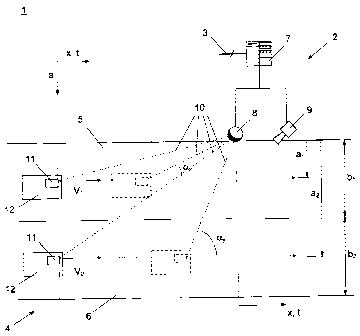
Figure 1 shows a road toll system 1 comprising a plurality of geographically
distributed radio beacons 2 (only one shown for representation), which connect
with a central
control unit (not shown) of the road toll system 1 via data connections 3. The
radio beacons 2
are respectively installed on a road 4 that can comprise multiple carriageways
or lanes 5, 6.
For example, the radio beacon 2 consists of a local computer 7, a
(transceiver/)
receiver 8 and a camera 9, which - operated by the computer 7 - can record
images of the
road 4 with its lanes 5, 6 for penalising toll violations.
CA 02755465 2011-10-18
6
The (transceiver/) receiver 8 serves to conduct radio communications 10 with
onboard
units or OBUs 11 carried by vehicles 12 passing the radio beacon 2 in the
lanes 5, 6. The
radio communications 10 are generally bidirectional data package connections.
An analysis
of the signals sent by the OBUs 11 to the (transceiver/) receiver 8 of the
radio beacon 2 is
sufficient for the purposes of the present invention, and therefore the
following will only
describe the OBU 11 sending signals 10 to the receiver 8 of the radio beacon
2. However, it is
understood that in practice signals are also sent in the opposite direction.
The vehicles 12 with the OBUs 11 travel in lanes 5, 6 at different speeds vi,
v2 past
the radio beacon 2, more precisely its receiver 8, at different passing or
normal distances al,
a2. In this case, the signals 10 emitted by the OBUs 11 are respectively
subject to frequency-
dependent Doppler shifts in accordance with the known formula
.fs (1)
1-
C
where
fs - transmission frequency of the signal 10 of the OBU 11
fD - Doppler-shifted receiving frequency of the signal 10 in the radio beacon
2 if
the OBU 11 were to move towards it front on;
v - speed of the OBU 11; and
c - speed of light.
If the OBU 11 travels past the distance 2 at a distance a, equation (1) can be
written
by means of geometric deliberations as
f~ = cos arctan a f(2)
x
where
a - vertical distance of the OBU 11 from the radio beacon 2 in the coordinate
system of Figure 1;
x - horizontal distance of the OBU 11 from the radio beacon 2 in the
coordinate
CA 02755465 2011-10-18
7
system of Figure 1; assuming a constant speed v or vi, V2 of the OBUs 11
the horizontal distance also simultaneously corresponds to time t; and
fB - Doppler-shifted receiving frequency of the signal 10 in the radio beacon
2
when the OBU 11 is moving past it at the distance a.
Figure 2 shows two exemplary curves of the receiving frequency fB in relation
to the
horizontal distance x or the time t. The solid line 13 shows the receiving
frequency curve for
the OBU 11 in lane 5 and the broken line 14 shows that for the OBU 11 in lane
6. As can be
seen, the Doppler-related frequency shift +Af,, Af2 in "far regions" 15, 16
of the frequency
curves 13, 14 far before and after a region 17 of maximum change fB' = afB/at
is small, i.e.
the frequency change fB' lies below a significance threshold c in the far
regions 15, 16.
Therefore, in the far regions 15, 16 (and naturally also further outside
these) the extent
of the Doppler shift Af is scarcely dependent on the passing distance a any
longer and
instead is almost exclusively dependent on the speed v. The effect of the
vehicle speed v on
the frequency curves 13, 14 can therefore be eliminated by scaling these so
that they
respectively assume the same value in the far regions 15, 16, e.g. a
predetermined value AF.
Figure 3 shows the result of such scaling, in which the indicated frequency
curves 13,
14 have been scaled ("normalised") so that they assume the predetermined
values AF in the
far regions 15, 16.
The scaled frequency curves 13', 14' therefore are more dependent on the ratio
a/x, i.e.
the passing distance a to the horizontal distance x or to the time t, in
accordance with the
following
fB = cos arctan (a)] (3)
X
As may be seen from Figure 3, the scaled frequency curves 13', 14' differ
particularly
clearly in their gradient fB' = aFB/at at the location x = t = 0, at which
their curve at the same
time shows an inflection point 20: the greater the passing distance a, the
"more abraded" the
CA 02755465 2011-10-18
8
scaled frequency curve 13', 14', i.e. the lower the gradient fB' at the
inflection point 20.
Therefore, the passing distance a is inversely proportional to the gradient
fB', i.e.
I = lim fB' (x) (4)
The gradient fB' at the inflection point 20 can be determined by
differentiating the
scaled frequency curves 13', 14', and the result of the differentiation is
shown in Figure 4.
With knowledge of the lane width b1, b2 of lanes 5, 6 - the respective lane 5,
6 in which the
OBU 11 was located during the transmission of its signal 10 can then be
determined from the
passing distances al, a2 determined in this manner. A simple relative
comparison of the
passing distances al, a2 is often also sufficient to determine the local
sequence of the vehicles.
It has been assumed hitherto that the transmitting frequency fs of the signal
10 of the
OBU 11 is constant, i.e. its own frequency curve is a constant curve. However,
it is also
possible that the OBU 11 transmits a signal 10 with a transmitting frequency
curve that is
non-constant in time, e.g. in the case of frequency hopping radio
communications, in which
the transmitting frequency fs constantly changes - according to a
predetermined or known
pattern. The recorded receiving frequency curves 13, 14 are recorded relative
to the prior
known curve of the transmitting frequency fs over time of the OBU 11, whether
it is constant
or changing, i.e. is referenced or normalised to these, so that the effect of
known changes in
transmitting frequency of the OBU 11 can be compensated.
Therefore, in summary, the method for determining the passing distance a of
the
OBUs 11 passing the radio beacon 2 is configured as follows:
Firstly, the frequency curve 13, 14 of the signal 10 of the OBU 11 is plotted
in
relation to time t (= x) - possibly based relatively on a prior known curve of
the transmitting
frequency fs over time. Then, the region 17 is approximately determined in the
frequency
curve 13, 14 at which a significant change indeed occurs, i.e. afB/at exceeds
a predetermined
detection threshold a. This serves to obtain a time reference point for
seeking the two far
regions 15, 16 which must lie before and after the change 17 and be so far
removed from this
that no further significant frequency change afB/at occurs in these, i.e. this
lies below a
predetermined significance threshold E.
CA 02755465 2011-10-18
9
With knowledge of the far regions 17, 18 and the Doppler shifts Afl, Af2
occurring
therein (which can also be considered to be quasi-constant because their
change does not
exceed the significance threshold s), the frequency curves 13, 14 can now be
scaled so that
they respectively assume the same predetermined value AF in their far regions
15, 16.
The inflection point 20 is then sought in the scaled frequency curves 13',
14'. For this,
the location x or the time t is sought in the frequency curves at which the
receiving frequency
fB assumes either the frequency mean value (the "middle") between the "quasi-
constant" far
regions 15, 16 or - if the rated frequency of the signal 10 of the resting OBU
11 is known -
assumes this rated frequency. The inflection point 20 can be determined in
both ways, i.e.
both before the scaling in the frequency curves 13, 14 and after the scaling
in the scaled
frequency curves 13', 14'.
After determining the inflection point 20, the gradient fB' (x--t=0) of the
scaled
frequency curves 13', 14' in the inflection point 20 can now be determined
(see Figure 4) and
the passing distance a or al, a2 can be determined therefrom, as explained
above.
Figure 5 shows an exemplary hardware configuration of the radio beacon 2 for
conducting the outlined method. Connecting to the receiver 8 the radio beacon
2 has a
memory 21, in which the time frequency curves 13, 14 of the received signals
10 are
recorded. A detector 22 connected to the memory 21 detects the change region
17 (afB/at > 6)
and feeds this information 17 to an evaluation device 23. The evaluation
device 23
determines the far regions 15, 16 of the frequency curves 13, 14 with afB/at <
s therefrom and
with this information 15, 16 actuates a scaling device 24 that scales the
frequency curves 13,
14 to scaled frequency curves 13', 14'. The latter are fed to a differentiator
25, which
calculates the gradient fB' (0) = afB/at at the location x = t = 0 of its
inflection point 20 in
order to determine the passing distances al, a2 therefrom.
The components 21 - 25 can be implemented, for example, by the local computer
8 of
the radio beacon 2.
The invention is not restricted to the represented embodiments, but covers all
variants
and modifications that fall within the framework of the attached claims.