Note: Descriptions are shown in the official language in which they were submitted.
CA 02755871 2011 MN
WO 2010/111796
PCT/CH2010/000048
- 1 -
MECHATRONIC LOCKING APPARATUS
The invention relates to a mechatronic locking
apparatus having a lock cylinder and an associated
security key which has a control circuit from which
information signals can be transmitted to a control
circuit of the lock cylinder via a first communication
path.
A mechatronic locking apparatus of this kind has been
disclosed, for example, in WO 2007/073608 by the same
applicant. Information signals can be transmitted to
the control circuit of the rotary lock cylinder by
means of the control circuit. Signals are transmitted
via an electrical contact element which is arranged in
the keyway of the rotary lock cylinder. One significant
advantage of a locking apparatus of this kind is that
increased security is possible by virtue of an
electronically secured user identification means. A
user identification means of this kind can result in it
being possible to operate the rotor using the inserted
key only by providing a predetermined item of
electronic information. The rotor is unlocked, for
example, by means of an actuator which has a blocking
element which can be moved between a blocking position
and an unblocked position by a motor.
The rotary lock cylinder of a locking apparatus of this
kind can be operated in a "stand-alone" manner or in a
networked manner. A networked system having a plurality
of mechatronic locking apparatuses is disclosed in
WO 2006/056085 by the same applicant. This system has a
computer having software for monitoring access
authorizations and having at least one database
containing data relating to the access authorizations.
The data generally comprises the names of the
authorized users, a list of the locking apparatuses to
which these users have access, and information, for
CA 02755871 2011 MN
WO 2010/111796 - 2 -
PCT/CH2010/000048
example, for time windows within which these users are
authorized to gain access. Systems of this kind make it
possible for mutations to be made from a control center
in a simple and quick manner via a network.
US 2005/0077995 discloses a locking apparatus having a
key with which user-specific data is transmitted to the
lock cylinder when the key is inserted into the lock
cylinder. The user-specific data is that from a
fingerprint sensor which is arranged on the grip of the
key. The lock cylinder can be operated when the user-
specific data has been identified as authorized and, in
addition, the rotor is mechanically unblocked by the
key. The user-specific data is transmitted from the key
to the lock cylinder by means of an electrical contact
in the lock cylinder or in a contactless manner. A
locking apparatus in which the locking security is
likewise intended to be increased by means of data from
a fingerprint sensor has also been disclosed by
WO 2005/013181. The locking apparatus according to EP-
A-0743411 has also disclosed that an electronic code
generator is arranged in the key and an electronic code
evaluation means is arranged in the cylinder housing.
The code is transmitted using a transponder and a
transponder reading device. WO 2009/036585 discloses a
lock device which has an electronic module for
receiving data from an identification unit and an
electric motor for operating the blocking and/or
coupling device. In the event of operation, the
electric motor acts as a generator in order to charge
the energy storage means for the electronic module.
The invention is based on the object of providing a
locking apparatus of said type which is even more
suitable for such systems.
In the case of a locking apparatus of this generic
type, the object is achieved in that the security key
CA 02755871 2011 MN
WO 2010/111796 - 3 -
PCT/CH2010/000048
has at least a second communication path for the
purpose of storing and/or processing access data. In
the locking apparatus according to the invention, the
security key has at least two communication paths. The
first communication path is created by means of an
electrical contact in the lock cylinder. A significant
advantage of the apparatus according to the invention
is that it is also possible to supply power via this
first communication path. This can be performed, in
particular, by means of a battery which is arranged in
the security key. However, the battery can, in
principle, also be arranged in the lock cylinder. The
two communication paths are each connected to the
control circuit of the security key. The locking
apparatus according to the invention can also be an
electronically secured lock cylinder which does not
have any mechanical security means, that is to say does
not contain bolts and pins as is otherwise customary.
The second communication path is RFID-based and allows
data to be read and input into the control circuit of
the security cylinder in a contactless manner by means
of a read device or write device. Therefore, in the
case of the locking apparatus according to the
invention, communication is possible via two paths. The
data in the control circuit which is arranged on the
security key can be used via the two communication
paths and therefore both via RFID and also via the
electrical contact in the lock cylinder. Irrespective
of the communication path, the access data can be
processed via a circuit. This is also true of other
data. This data can be written, read and changed both
via the first and via the second communication path,
and also centrally stored and managed.
According to a development of the invention, provision
is made for the control circuit in the lock cylinder to
be performed by means of bidirectional communication.
CA 02755871 2016-05-17
-4-
Power is also supplied via the same electrical connection. In
addition, provision is made for the control circuit of the lock
cylinder to communicate with the control circuit of the security
key by means of a modulated current.
According to a development of the invention, provision is made
for the data to be transmitted in encrypted form via the first
and via the second communication path, and also to be stored in
encrypted form. Provision is also made, according to one
development of the invention, for the security key to contain an
identification and/or authentication mechanism. The data for
identification and authentication are preferably transmitted and
stored in encrypted form.
According to one development of the invention, provision is made
for the control circuit which is arranged in the key to have a
clock which can be read from and changed via the two
communication paths. The authorization for manipulation is
therefore possible by means of data management via the two
communication paths.
In accordance with one embodiment of the invention, there is
provided a mechatronic locking apparatus comprising a lock
cylinder and an associated security key which has a first
control circuit from which information signals can be
transmitted to a second control circuit of the lock cylinder via
a first communication path, wherein the security key has at
least a second communication path for the purpose of at least
one of storing and processing access data, wherein the first and
second communication paths are connected to said first control
circuit of the security key, wherein access data can be written,
read and changed both via the first and via the second
communication path, wherein the first communication path on the
security key has electrical contact means which are in contact
with electrical contact means of the lock cylinder, for the
purpose of signal transmission, when the key is inserted into a
CA 02755871 2016-05-17
-4a-
keyway in the lock cylinder, and wherein the second
communication path has a transponder.
Further advantageous features can be found in the dependent
patent claims, the following description and the drawings.
An exemplary embodiment of the invention will be explained in
greater detail below with reference to the drawings, in which:
fig. 1 schematically shows a locking apparatus according to
the invention,
fig. 2 shows a view of the front face of a lock cylinder of
the locking apparatus according to the invention, and
CA 02755871 2011 MN
WO 2010/111796 - 5 -
PCT/CH2010/000048
fig. 3 shows
a circuit diagram of the locking
apparatus according to the invention.
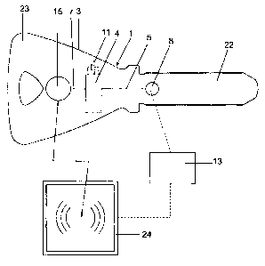
The locking apparatus 1 according to the invention has,
according to figure 1, a security key 3 which has a
shank 22 and a grip 23. The security key 3 is used to
operate the lock cylinder 2 which is shown in figure 2.
Said lock cylinder has a rotor 25 and a stator 26 for
enabling the rotor 25 to rotate, for which purpose the
shank 22 of the key is inserted into a keyway 10 in the
rotor. In this case, tumblers (not shown here) are
arranged in a manner which is known per se.
A control circuit 4 which is fed by an energy source
11, in particular a battery, is arranged in the grip 23
of the key 3. The control circuit 4 and the energy
source 11 are arranged, for example, in a recess (not
shown here) in the grip 23 and covered by a cover or
the like (not shown here). The control circuit 4 is
used, in particular, for storing and processing access
data. This access data can be written to the control
circuit 4, read from said control circuit and changed
by means of a control center 13, for example by means
of a laptop. This data can be stored and managed in the
control center 13. Communication for these processes is
possible via two paths. Said paths will be described in
greater detail below.
The first path, via which the control center 13 can
communicate with the control circuit 4, has a first
communication path 5 which connects the control circuit
4 to a contact means 8 which is arranged on the
security key 3. This contact means 8 is, for example, a
contact plate which is arranged on the outside at the
rear end of the shank 22. If the shank 22 is inserted
into the keyway 10, the contact means 8 is electrically
connected to a contact means 9 which, according to
CA 02755871 2011 MN
WO 2010/111796 - 6 -
PCT/CH2010/000048
figure 2, is arranged like in the keyway 10. This first
communication path 5 is formed by a signal line which
connects the control circuit 4 to the contact means 8.
Said signal line runs in the key 3. The contact means 9
is connected to a control circuit 6 which, according to
figure 2, is arranged in the stator 26. Said control
circuit 6 controls, for example, an actuator which is
described, for example, in WO 2007/073608. If the shank
22 is inserted into the keyway 10, the control circuit
4 transmits the authorization data to the control
circuit 6 via the first communication path 5. This data
is checked in the control circuit 6. If authorization
is granted, the actuator is accordingly operated.
If the security key is a reversible key, both sides of
the key or both sides of the keyway are provided with
an electrical contact element.
The second path has a second communication path 7 which
connects the control circuit 4 to a transponder 15
which is known per se and which is likewise arranged in
the grip 3. This transponder 15 has an antenna 27
(figure 3) which is known per se and which allows
contactless communication with a read device 24. The
transponder 15 allows RFID-based transmission of data
between the circuit 4 and the control center 13 which
is connected to the read device 24 for signal
transmission. This read device 24 can be used to read
data from, input data into and change data in the
control circuit. In addition, the data in the control
center 13 can be stored and then managed in said
control center by means of the read device 24.
Therefore, in the locking apparatus according to the
invention, data transmission is possible by means of
the contacts 8 and 9, and RFID-based data transmission
or communication is also possible. As mentioned above,
feeding via the first communication path 5 is possible.
In addition, energy can be supplied via the antenna 27
CA 02755871 2011 MN
WO 2010/111796 - 7 -
PCT/CH2010/000048
of the transponder 15 or via RFID. As shown in figure
3, a power control means 16 which is connected to the
energy source 11 and to a voltage converter 12 is
provided. This power control means 16 switches at least
parts of the circuit 4 on and off in order to keep the
energy consumption as low as possible. Many batteries
have, on account of their internal resistance, a large
voltage drop at current peaks. The voltage converter 12
makes it possible to compensate for a voltage drop in
the battery. In order to reduce the quiescent current,
the voltage converter 12 is preferably switched off in
the inoperative state. When the key 3 is inserted into
the lock cylinder 2, the voltage converter 12 is
switched on and compensates. The voltage drop which was
caused by the current peaks. According to figure 3, the
control circuit 4 has a system detector 20 which
switches on the respectively required process. The
switch-on operation is performed on the basis of the
relevant system and therefore selectively via the first
communication path 5 or via the second communication
path 7. The system detector 20 is accordingly connected
to the contact means 9 or to the transponder 15.
The circuit 4 also has encryption means 17 and a clock
14. The clock 14 is protected by the encryption means
17. The clock 14 can be read from and changed both via
the first communication path 5 and via the second
communication path 7. The authorization for
manipulation of the clock 14 is controlled by the data
processing means.
The control center 13 is likewise protected by an
encryption means 19. Said control center has at least
one data storage means 18 and means for data management
21. The control center 13 can, as shown, communicate
with the control circuit 4 via the first communication
path 5 or via the second communication path 7. In
addition, a firmware update can be carried out via the
CA 02755871 2011 MN
WO 2010/111796 - 8 -
PCT/CH2010/000048
first communication path 5 and via the second
communication path 7.
Communication is performed by means of the second
communication path 7 in accordance with the
respectively indicated standards of the transponder
technology used. One or more RFID technologies can be
processed, for example, at frequencies of 13.56 MHz or
125 kHz. The control circuit 4 can be directly
connected to the RFID antenna 27 and communicate via
said RFID antenna.
Provision is made for the storage and processing of the
following data and characteristics in particular:
uniqueness numbers
access authorizations
time zones
time windows
block lists/withdrawal of authorization
status information
history information
segmentation of data for third party users
grouping of users
CA 02755871 2011 MN
WO 2010/111796 - 9 -
PCT/CH2010/000048
LIST OF REFERENCE SYMBOLS
1 Locking apparatus
2 Lock cylinder
3 Security key
4 Control circuit
5 First communication path
6 Control circuit
7 Second communication path
8 Contact means
9 Contact means
10 Keyway
11 Energy source
12 Voltage converter
13 Control center
14 Clock
15 Transponder
16 Power control means
17 Encryption means
18 Data storage means
19 Encryption means
20 System detector
21 Data processing means
22 Shank
23 Grip
24 Read device
25 Rotor
26 Stator
27 Antenna
(RFID antenna)