Note: Descriptions are shown in the official language in which they were submitted.
CA 02756108 2011-10-19
A METHOD OF ALERTING HORN RULE TIMING
BACKGROUND AND SUMMARY OF THE DISCLOSURE
[0001] Since the inception of the railroad, the horn (whistle) has been an
important device
which is intended to warn people and animals near railroad tracks of an
oncoming train.
Key areas or points of interest where the railroads have focused on the use of
the horn
through the years are railroad crossings. Many years ago railroads began
placing "whistle"
boards near the track in advance of road crossings to remind the engineers to
sound their
horn. The locations of these boards were based on the particular maximum speed
the train
was allowed to travel on the track at the time they were placed. The distance
was
calculated to ensure a particular horn cadence could be sounded far enough in
advance of
and through the crossing. Over time crossing have been moved, tracks changed,
and
maximum speeds modified.
[0002] Over the past two decades, the Untied States Federal Railway
Administration
FRA, has started to mandate and enforce very strict rules regarding the use of
the horn.
This includes both when it should be sounded as well as when it should not.
These
restrictions have placed very tight restrictions on the engineers to properly
sound the horn.
The most difficult problem with this is that the rules are based on time and
not distance.
This means that the location at which the engineer is required to begin to
sound the horn is
variable as it ultimately varies based on the speed of the train. Since the
speed of the train
is dependent on many factors including civil speed limits, daily speed
restrictions, weight
of the train, horsepower, track geometry, and others, the location at which
the engineers are
required start sounding the horn and stop sounding the horn are becoming more
and more
critical. To aid in the determination of this the railroad has in many cases
given their
engineers tables which they can carry that give them a distance when they need
to begin
sounding the horn prior to the crossing based on their speed. The problem with
this is that
the engineers still aren't exactly aware what the distance to the crossing is.
[0003] The present method uses, for example the LEADER's system look ahead
and
display capabilities to determine and alert by display or indicators which
inform the
engineer or operator of the earliest location on the track at which the horn
can be sounded.
Additionally, indicators could be displayed which will allow the engineer to
know the
1
CA 02756108 2011-10-19
locations up to which the horn must be sounded and can no longer be sounded or
not
sounded at all.
[0004] The present method includes determining the locomotive's present
location on
the track; and determining the present speed of the locomotive. From the
present location
of the locomotive and the present speed of the locomotive, a horn rule
location on the
track for a point of interest is determined; and the operator is alerted to
horn start location
on the track.
[0005] A speed profile from the present position to the point of interest may
be
determined and used to determine the horn start location on the track. The
horn rule
locations may include a horn may start location, a horn must start location
and a horn stop
location on the track for the point of interest and may be determined and
displayed. The
length of time required for a selected horn cadence may be determined and used
to
determine the horn start location on the track. The specific horn rule
parameters of timing
for various horn locations may be communicated to the locomotive via a method
which
allows modification .and specification of the parameters prior to departure or
in route
automatically or by the engineer via an input device.
[0006] The method is performed by software on a processor or computer on the
locomotive.
[0007] These and other objects, features, and advantages of the present
disclosure may be
better understood and appreciated from the following detailed description of
the
embodiments thereof, selected for purposes of illustration and shown in the
accompanying
drawings.
BRIEF DESCRIPTION OF THE DRAWINGS
[0008] Figure 1 is a display incorporating the horn rule timing according to
the principles of
the present disclosure.
[0009] Figure 2 is a flow chart for determining the horn rule timing according
to the present
disclosure.
-2-
CA 02756108 2011-10-19
DETAILED DESCRIPTION OF THE PREFERRED EMBODIMENTS
[00010] For the present method, the LEADER system by New York Air Brake will
be
used as an example of a processor or computer on which the method can be
performed.
Other processors or computers on the locomotive may be used. The LEADER
system
simulates the entire train movement in real time and with its look-ahead
technology,
can predict the train dynamics on a forward looking basis. This capability is
used to
provide the engineer with "driver assist prompts" in order to optimize the
train handling
with respect to in train forces, fuel economy, standard operating practices
and time to
destination. These parameters are weighted according to the requirements of
the client
railroad. An explanation of the LEADER system is found in U.S. Patent
6,587,764,
which is incorporated herein by reference.
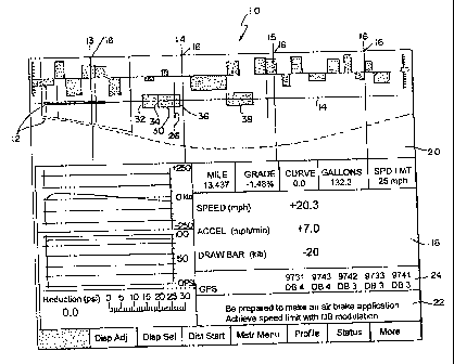
[00011] Figure 1 illustrates a display 10 within the cabin of the locomotive.
Reference to
Figure 5 of U.S. Patent 6,144,901 provides details of the various elements of
the display.
Only those of interest to the present disclosure will be described in detail.
A train 12 is
shown on a track 14. There is a vertical and a horizontal display of the train
on the track.
Sign posts 16 are illustrated crossing the various track locations. The box 18
displays the
present speed, the acceleration and draw bar forces.
[00012] Other messages that may be provided to the operator includes message
box 22
which provides, for example, a message "be prepared to make an air brake
application"
and "achieves speed limit through the DB modulation." DB is dynamic brake. Box
24
may show a suggested dynamic brake application at a specific GPS location or
the current
propulsion system setting for each locomotive and the status of the GPS
system, for
example. The DB numbers are representative of a notch of the propulsion handle
in the
dynamic brake region.
[00013] As will be described with respect to Figure 2, the present system
determines the
present location of the locomotive on the track and locomotive speed. From the
present
location of the locomotive, the present speed of the locomotive, and the
parameters related
to the horn rule ( time/distance to start in advance and applicability to the
point of
interest), a horn start location on the track when the horn is to begin
blowing for a point of
interest is determined. The horn start location on the track is displayed.
Also, a may start
-3-
CA 02756108 2011-10-19
blowing, a must start blowing, a stop blow locations and horn free zones may
be
determined and displayed A speed profile from the present position to the
point of interest
may be determined and used to determine the horn start location on the track.
The length
of time required for a selected horn cadence may be determined and used to
determine the
horn start location on the track.
[00014] The horn rule timing is illustrated in Figure 1 by the boxes 20. The
point of
interest 26 may be for example a rail crossing. The indicia 30 is a zone of
horn activation
and includes a horn may start location 32, a horn must start location 34 and a
horn stop
location 36 on the track for the point of interest. Also shown is a horn free
zone 38. The
operator may also be alerted to the horn rule location by displaying the horn
rule as a
message as the locomotive is at the horn rule location and/or activating an
audio or visual
indicator as the locomotive is at the hom rule location.
[00015] A flow chart of the present method is illustrated in Figure 2. At step
40, there is a
determination of train speed and track location. At step 42, there is a
determination or
calculation of a horn rule location along the track based on the present speed
and location.
The horn rule location at a minimum would be a horn must start location 34 and
may
include a horn may start location 32, based on local ordinances and track
restrictions
supplied by step 50. Also, a horn stop location 36 and horn free zones 38 may
be
determined based on data supplied from step 50. At step 44, the operator is
alerted to the
horn locations by display or indicators for example.
[00016] The horn rule parameter data acquired at step 50 includes, for
example, a start
parameter, a total duration parameter, a stop parameter, a cadence parameter,
a location
applicability parameter, etc. This data may be communicated to the locomotive
via a
method which allows modification and specification of the parameters prior to
departure
or in route automatically or by the engineer via an input device. The
parameter data may
be general for all points of interest or may be specific for each or some
points of interest.
[00017] The location at which the engineer is required to begin to sound the
horn is variable
as it is dependent on the speed of the train. Since the speed of the train is
dependent on
many factors including civil speed limits, daily speed restrictions, weight of
the train,
horsepower, track geometry, and others, a more accurate determination of the
horn rule
-4-
CA 02756108 2011-10-19
locations on the track may be determined at step 46. A speed profile is
determined from the
present location to the point of interest 26. The speed profile is determined
from the present
speed and location from step 40 and one or more of time to point of interest,
speed limits
between the present position and the point of interest, track topology between
the present
position and the point of interest, weight of the train, horse power, fuel
usage, throttle
control settings, brake control settings, and train forces. These are part of
the calculations
that can be performed on the LEADER system. This more accurate information
from
step 46 is used in step 42 to determine more precise horn rule locations.
[00018] The horn rule locations may also vary base on the horn cadence. This
would
include the length of time of the cadence and how long the cadence should
continue
through and after the point of interest. Step 48 determines the length of time
of the
cadence as supplied by step 50 and provides this information to step 42 for
the
determination of the horn rule locations.
[00019] Accordingly, it will be understood that the preferred embodiment of
the present
invention has been disclosed by way of example and that other modifications
and
alterations may occur to those skilled in the art. Although the use of the
LEADER system
and displays has been discussed, the disclosed processes and displays may be
used on any
locomotive display.
-5-