Note: Descriptions are shown in the official language in which they were submitted.
CA 02756317 2011-10-25
SURGICAL RETRIEVAL APPARATUS FOR THORACIC PROCEDURES
BACKGROUND
Technical Field
[0001] The present disclosure relates to a retrieval apparatus, and more
particularly, to a
surgical retrieval apparatus for use in thoracic surgical procedures.
Background of Related Art
[0002] In minimally invasive surgical procedures, operations are carried out
within the body
by using elongated instruments inserted through small entrance openings in the
body. The initial
opening in the body tissue to allow passage of instruments to the interior of
the body may be a
natural passageway of the body, or it can be created by a tissue piercing
instrument such as a
trocar, or created by a small incision into which a cannula is inserted.
[0003] Because the tubes, instrumentation, and any required punctures or
incisions are
relatively small, the surgery is less invasive as compared to conventional
surgical procedures in
which the surgeon is required to cut open large areas of body tissue.
Therefore, minimally
invasive surgery minimizes trauma to the patient and reduces patient recovery
time and hospital
costs.
[0004] Minimally invasive procedures may be used for partial or total removal
of body tissue
or organs from the interior of the body, e.g. nephrectomy, cholecystectomy,
lobectomy and other
procedures including thoracic, laparoscopic and endoscopic procedures. During
such
procedures, it is common that a cyst, tumor, or other affected tissue or organ
needs to be
removed via the access opening in the skin, or through a cannula. Various
types of entrapment
devices have been disclosed to facilitate this procedure. In many procedures
where cancerous
tumors are removed, removal of the specimen in an enclosed environment is
highly desirable to
prevent seeding of cancer cells.
[0005] In minimally invasive thoracic surgery, access to the thoracic cavity
is limited as well
as maneuverability within the cavity as the access port is placed between the
confined space
between a patient's ribs. Such procedures, commonly referred to as video
assisted thorascopic
surgery (VATS), aim to reduce patient recovery time by accessing the thoracic
cavity through
the natural intercostal space without spreading the ribs as in open
procedures. This restricted
-1-
CA 02756317 2011-10-25
access can sometimes cause problems when removing large specimens. Moreover,
in such
procedures, e.g. thorascopic wedge resection and lobectomy, it is often
necessary to remove a
portion of the lung and retrieve it relatively intact for pathology. It is
also important that the
specimen be sufficiently contained to prevent seeding of cancer cells during
manipulation and
removal.
[0006] In designing such specimen retrieval instrumentation, a balance must be
struck
between the need to provide a retrieval apparatus with a strong enough
containment bag to
prevent tearing or rupture while providing sufficient rigidity to enable
manipulation and removal.
Another balance which needs to be achieved is to provide sufficient
maneuverability while
reducing tissue trauma, e.g. damaging lung tissue, during manipulation and
removal.
Additionally, the instrumentation on one hand should be able to be inserted
through a small
access incision or port while on the other hand able to accommodate a wide
range of patient sizes
and be able to easily remove large specimens and minimize risk of seeding.
SUMMARY
[0007] In accordance with one aspect of the present disclosure, a surgical
retrieval apparatus
is provided. The surgical retrieval apparatus in one aspect includes a housing
defining a
longitudinal axis and having an elongated sleeve extending distally therefrom.
The housing and
the elongated sleeve cooperate to define a lumen extending longitudinally
therethrough. A shaft
having an end effector assembly disposed at a distal end thereof is configured
for selective
translation through the lumen of the housing and elongated sleeve between a
first position and a
second position. In the first position, the end effector assembly is disposed
within the elongated
sleeve. In the second position, the shaft is translated distally through the
lumen such that the end
effector assembly extends distally from the elongated sleeve. An articulation
mechanism
coupled to the end effector assembly is configured for selectively
articulating the end effector
assembly with respect to the longitudinal axis when the shaft is disposed in
the second position.
Articulation of the end effector assembly is inhibited when the shaft is
disposed in the first
position. A specimen retrieval bag is coupled to the end effector assembly.
The specimen
retrieval bag is deployed from an un-deployed, or retracted position, to an
extended position
upon movement of the end effector assembly from the first position to the
second position.
-2-
CA 02756317 2011-10-25
[0008] In some embodiments, the shaft is manually translatable between the
first and second
positions, i.e., the shaft may be selectively translated by a hand of the
clinician.
[0009] In some embodiments, a locking mechanism (or locking mechanisms) is
provided for
retaining the shaft in the first position and/or the second position.
[0010] In some embodiments, a release trigger may be provided, e.g., disposed
on the
housing, such that, upon actuation, the shaft is released, or unlocked,
permitting the clinician to
manually translate the shaft from the second position back to the first
position. Further, in such
embodiments, upon actuation of the release trigger, a plunger may be extended
proximally from
the shaft to facilitate manual translation of the shaft from the second
position back to the first
position, e.g., via grasping the plunger.
[0011] In some embodiments, the specimen retrieval bag is released from the
end effector
assembly upon translation of the shaft from the second position back to the
first position.
Additionally, an interference member may be provided to inhibit the specimen
retrieval bag from
being retained on the end effector assembly upon translation of the shaft from
the second
position back to the first position.
[0012] In some embodiments, a cinch cord is coupled at a distal end thereof to
an open end
of the specimen retrieval bag and is releasably engaged at a proximal end
thereof to the shaft,
wherein upon translation of the shaft from the second position back to the
first position, the cinch
cord is pulled proximally to cinch the open end of the bag closed. Further, a
releasable latch may
be configured to engage the proximal end of the cinch cord to the shaft, such
that when the shaft
is disposed in the first position, the releasable latch may be released to
disengage the cinch cord
from the shaft.
[0013] In some embodiments, the articulation mechanism includes an
articulation wheel
coupled to an articulation bar. The articulation wheel can be selectively
rotatable about the
longitudinal axis to longitudinally translate the articulation bar along the
longitudinal axis. The
articulation bar, in turn, can be configured to urge the end effector assembly
to pivot relative to
the shaft, thereby articulating the end effector assembly relative to the
longitudinal axis.
[0014] In accordance with another aspect, a surgical retrieval apparatus is
provided which
includes a housing defining a longitudinal axis and having an elongated sleeve
extending distally
therefrom. The housing and the elongated sleeve cooperate to define a lumen
extending
longitudinally therethrough. A shaft having an end effector assembly disposed
at a distal end
-3-
CA 02756317 2011-10-25
thereof is selectively translatable through the lumen between a first
position, wherein the end
effector assembly is disposed within the elongated sleeve, and a second
position, wherein the end
effector assembly extends distally from the elongated sleeve. An articulation
mechanism is
coupled to the end effector assembly. The articulation mechanism is
transitionable from a
disengaged state to an engaged state upon translation of the shaft from the
first position to the
second position. A specimen retrieval bag is supported by the end effector
assembly.
[0015] In some embodiments, in the engaged state, rotation of the articulation
mechanism
articulates the end effector assembly relative to the longitudinal axis.
[0016] In some embodiments, the articulation mechanism includes an
articulation wheel
coupled to an articulation bar upon transitioning of the articulation
mechanism to the engaged
state. Accordingly, in such embodiments, in the engaged state, the
articulation wheel may be
selectively rotated to translate the articulation bar along the longitudinal
axis, and as the
articulation bar is translated along the longitudinal axis, the end effector
assembly is urged to
articulate, i.e., pivot, relative to the longitudinal axis.
[0017] A clutch can be provided coupled to the articulation wheel such that
rotation of the
articulation wheel effects longitudinal translation of the clutch. The clutch,
in turn, can include
an engagement arm configured to engage the articulation bar upon transition of
the articulation
mechanism to the engaged state. A collar can be provided to bias the
engagement arm of the
clutch into engagement with the articulation bar upon translation of the shaft
from the first
position to the second position, e.g., upon transition of the articulation
mechanism from the
disengaged state to the engaged state.
[0018] In some embodiments, a release trigger is provided. The release trigger
can be
configured, upon actuation, to permit manual translation of the shaft from the
second position
back to the first position. Further, the release trigger may be configured to
transition the
articulation mechanism to the disengaged state upon actuation thereof. The
surgical retrieval
apparatus may otherwise be configured according to any of the other
embodiments discussed
herein.
[0019] In accordance with another aspect of the present disclosure, a surgical
retrieval
apparatus is provided which includes a housing having an elongated sleeve and
a lumen
extending therethrough. A shaft including an end effector assembly disposed at
a distal end
thereof is translatable between a first position, wherein the end effector
assembly is disposed
-4-
CA 02756317 2011-10-25
within the elongated sleeve, and a second position, wherein the end effector
assembly extends
distally from the elongated sleeve. A releasable latch is coupled to the shaft
and is transitionable
between an open condition and a closed condition. A specimen retrieval bag is
releasably
disposed on the end effector assembly and includes a cinch cord coupled to an
open end thereof.
The cinch cord extends proximally from the specimen retrieval bag to be
engaged within the
releasable latch. When the shaft is disposed in the first position, the
releasable latch is operable,
e.g. exposed from the housing, permitting manual manipulation of the
releasable latch to release
the cinch cord e.g., the latch can move between the open condition and the
closed condition.
When the shaft is disposed in the second position, the releasable latch is
inoperable, e.g.
positioned within the housing, inhibiting manual manipulation of the
releasable latch, e.g.,
inhibiting access to the releasable latch. The surgical retrieval apparatus
may otherwise be
configured similarly to any of the other embodiments discussed herein.
[0020] In some embodiments, the releasable latch is retained in the closed
condition via a
protrusion-aperture engagement.
[0021] In another aspect, a surgical retrieval apparatus is provided which
includes a housing
having an elongated sleeve extending therefrom. A lumen extends through the
housing and
elongated sleeve. A shaft having an end effector assembly disposed at a distal
end thereof is
translatable between a first position and a second position. A plunger is
slidably coupled to a
proximal end of the shaft. The plunger is transitionable between a first
condition, wherein the
plunger is substantially disposed within the shaft, and a second condition,
wherein the plunger
substantially extends proximally from the shaft. A release trigger disposed on
the housing is
selectively actuatable to transition the plunger from the first condition to
the second condition to
facilitate translation of the shaft from the second position back to the first
position.
[0022] In some embodiments, transitioning the plunger from the first condition
to the second
condition is inhibited when the shaft is disposed in the first position.
[0023] In some embodiments, when the shaft is disposed in the second position
and the
plunger is disposed in the first condition, the plunger is substantially flush
with the housing,
while when the shaft is disposed in the second position and the plunger is
disposed in the second
condition, the plunger extends proximally from the housing.
[0024] In some embodiments, upon actuation of the release trigger, a distal
finger of the
plunger is disengaged from an aperture defined within the shaft permitting the
plunger to
-5-
CA 02756317 2011-10-25
transition to the second condition. The surgical retrieval apparatus may
otherwise be configured
according to any of the other embodiments discussed herein.
[0025] A method of specimen retrieval is also provided in accordance with
another aspect of
the present disclosure. The method includes providing a surgical retrieval
apparatus according to
any of the embodiments discussed above. The method further includes inserting
the shaft
partially into the lumen through a proximal end of the housing to the first
position, inserting the
surgical retrieval apparatus through an opening in tissue, translating the
shaft distally through the
lumen to the second position, and articulating the end effector assembly with
respect to the
longitudinal axis to position an open end of the specimen retrieval bag
adjacent the specimen of
tissue to be retrieved.
[0026] In some embodiments, the method further includes translating the shaft
proximally
from the second position back to the first position such that the end effector
assembly is once
again disposed within the lumen.
[0027] In some embodiments, the method further includes locking the shaft in
the first
position and/or the second position. In such embodiments, a release trigger
may be actuated to
release, or unlock, the shaft to permit manual translation of the shaft
between the first and second
positions.
[0028] In some embodiments, the method further includes disengaging the
proximal end of
the cinch cord from the shaft upon movement of the shaft from second position
back to the first
position.
[0029] In some embodiments, the method further includes selectively rotating
an articulation
wheel about the longitudinal axis to articulate the end effector assembly
relative to the
longitudinal axis.
BRIEF DESCRIPTION OF THE DRAWINGS
[0030] Various embodiments of the subject surgical retrieval apparatus are
described herein
with reference to the drawings wherein:
[0031] Fig. I is a side, perspective view of one embodiment of a surgical
retrieval apparatus
in accordance with the present disclosure;
[0032] Fig. 2 is an exploded, perspective view of a housing of the surgical
retrieval apparatus
of Fig. 1;
-6-
CA 02756317 2011-10-25
[0033] Fig. 3 is an exploded, perspective view of a shaft and end effector
assembly of the
surgical retrieval apparatus of Fig. 1;
[0034] Fig. 4 is a side, perspective view of the surgical retrieval apparatus
of Fig. 1 shown in
an insertion position;
[0035] Fig. 5 is a side, perspective view of the surgical retrieval apparatus
of Fig. 1 showing
the end effector assembly in the deployed (extended) position;
[0036] Fig. 6 is a side, perspective view of the surgical retrieval apparatus
of Fig. 1 showing
the end effector assembly articulated relative to the shaft;
[0037] Fig. 7 is a side, perspective view of the surgical retrieval apparatus
of Fig. 1, wherein
a plunger has been released to permit retraction of the end effector assembly;
[0038] Fig. 8 is a side, perspective view of the surgical retrieval apparatus
of Fig. 1, wherein
the shaft and the end effector assembly have been returned to the insertion
position to close the
specimen retrieval bag;
[0039] Fig. 9 is a side, perspective view of the surgical retrieval apparatus
of Fig. 1 wherein
the specimen retrieval bag has been released from the surgical retrieval
apparatus;
[0040] Fig. 10 is a side, cut-away view of the surgical retrieval apparatus of
Fig. 1 shown in
the insertion position, corresponding to the position of Fig. 4;
[0041] Fig. 11 is a side, cut-away view of the surgical retrieval apparatus of
Fig. 1 shown
with the end effector assembly in the deployed (extended) position,
corresponding to the position
of Fig. 5 (the retrieval bag removed for clarity);
[0042] Fig. 12 is an enlarged, longitudinal, cross-sectional view of an
articulation assembly
of the surgical retrieval apparatus of Fig. 1 wherein the articulation
assembly is disposed in an
engaged position;
[0043] Fig. 13 is a side, cut-away view of the surgical retrieval apparatus of
Fig. 1 shown
with the end effector assembly articulated relative to the shaft,
corresponding to the position of
Fig. 6 (the retrieval bag removed for clarity);
[0044] Fig. 14 is an isolated, rear, perspective view of an articulation wheel
of the
articulation assembly of the surgical retrieval apparatus of Fig. 1;
[0045] Fig. 15 is an isolated, side view of an articulation bar of the
articulation assembly of
the surgical retrieval apparatus of Fig. 1 shown pivotably engaged to the end
effector assembly;
-7-
CA 02756317 2011-10-25
[0046] Fig. 16 is a longitudinal, cross-sectional view of the housing of the
surgical retrieval
apparatus of Fig. 1 shown in the deployed position;
[0047] Fig. 17 is a transverse, cross-sectional view of the housing of
surgical retrieval
apparatus of Fig. 1 shown in the deployed position;
[0048] Fig. 18 is a longitudinal, cross-sectional view of the housing of the
surgical retrieval
apparatus of Fig. 1 wherein the plunger has been released;
[0049] Fig. 19 is a transverse, cross-sectional view of the surgical retrieval
apparatus of Fig.
1 similar to Fig. 17. wherein the plunger has been released;
[0050] Fig. 20 is a front, perspective view of the end effector assembly of
the specimen
retrieval apparatus of Fig. 1 shown including an interference member disposed
at a distal end of
the sleeve; and
[0051] Fig. 21 is a rear, perspective view of the specimen retrieval apparatus
of Fig. 1,
wherein the shaft has been returned to the insertion position and wherein a
releasable latch has
been opened to disengage the cinch cord of the specimen retrieval bag from the
specimen
retrieval apparatus.
DETAILED DESCRIPTION
[0052] Various embodiments of the presently disclosed surgical retrieval
apparatus, and
methods of using the same, will now be described in detail with reference to
the drawings
wherein like references numerals identify similar or identical elements. In
the drawings, and in
the following description, the term "proximal" should be understood as
referring to the end of the
apparatus, or component thereof, that is closer to the clinician during proper
use, while the term
"distal" should be understood as referring to the end that is farther from the
clinician, as is
traditional and conventional in the art.
[0053] Although the presently disclosed surgical retrieval apparatus is
discussed with respect
to minimally invasive thoracic procedures, it is within the scope of the
present disclosure that the
surgical retrieval apparatus is readily adaptable for use in other minimally
invasive surgical
procedures, including for example laparoscopic procedures.
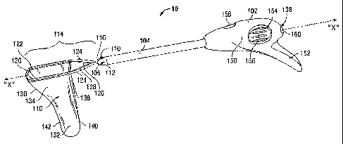
[0054] Turning now to Figs. 1 and 2, a surgical retrieval apparatus in
accordance with the
present disclosure is shown generally identified by reference numeral 10.
Surgical retrieval
-8-
CA 02756317 2011-10-25
apparatus 10 includes a housing 102 defining a longitudinal axis "X-X" and an
elongated sleeve
104 extending distally from housing 102. Housing 102 defines a longitudinal
passageway 106a
extending therethrough, while elongated sleeve 104 defines a lumen 106b
extending
longitudinally therethrough. Passageway 106a and lumen 106b cooperate to
define a channel
106 disposed about longitudinal axis "X-X" and extending distally from
proximal aperture 108
of housing 102, through housing 102, through elongated sleeve 104, and through
distal aperture
110 of elongated sleeve 104, i.e., channel 106 extends completely through
surgical retrieval
apparatus 10. A shaft 112 including an end effector assembly 114 pivotably
coupled thereto at a
distal end 116 thereof is slidably positionable within channel 106. More
particularly, as will be
described in greater detail below, shaft 112 is longitudinally translatable
between a first, or
insertion (and removal) position, wherein shaft 112 is inserted partially
through proximal
aperture 108 into channel 106 such that end effector assembly 114 is disposed
within channel
106, and a second, or extended position, wherein shaft 112 is translated
further distally through
channel 106 such that end effector assembly 114 extends distally from distal
aperture 110 of
elongated sleeve 104.
[0055] With continued reference to Fig. 1, a specimen retrieval bag 118 is
removably
coupled to end effector assembly 114 and depends therefrom. More specifically,
as shown in
Fig. 1, specimen retrieval bag 118 is folded over at an open end 120 thereof
to form a loop 122
around the outer periphery thereof. End effector assembly 114 includes a pair
of arms 124
configured for positioning within loop 122 formed at open end 120 of specimen
retrieval bag 118
to retain specimen retrieval bag 118 thereon. In the extended position, as
shown in Fig. 1, arms
124 of end effector assembly 114 define a spaced-apart, curvate configuration
for retaining
specimen retrieval bag 118 thereon in an open condition, although other
configurations are also
contemplated, e.g., end effector assembly 114 may include linear arms 124.
Further, as will be
described in greater detail below, a cinch cord 126 is disposed through loop
122 of specimen
retrieval bag 118 at a first end 128 thereof and is engaged to shaft 112 at a
second end 130 (Fig.
21) thereof, such that, upon proximal translation of shaft 112 relative to
specimen retrieval bag
118, open end 120 of specimen retrieval bag 118 is cinched closed.
[0056] It is envisioned that specimen retrieval bag 118 be formed from any
suitable bio-
compatible material (or materials), e.g., 30 Denier Ripstop Nylon, configured
to retain a
specimen of tissue "S" (Figs. 7-9) therein and to inhibit the passage of
fluids and biological
-9-
CA 02756317 2011-10-25
materials therethrough. The bag can include a coating, such as a polyurethane
coating, to
prevent egress of fluid if a permeable bag is utilized or to improve the
impermeability. The
coating can be placed on the inner surface and/or the outer surface of the
bag. As shown in Fig.
1, specimen retrieval bag 118 includes a lower portion 132 having a minimized
cross-section
configured to re-orient or re-position the specimen of tissue "S" (Figs. 7-9)
within specimen
retrieval bag 118 to facilitate removal of specimen retrieval bag 118 from an
internal body
cavity, and a relatively expansive upper portion 134 configured to facilitate
positioning of
relatively large specimen of tissue "S" (Figs. 7-9) within specimen retrieval
bag 118. In other
words, lower portion 132 has a smaller transverse dimension than the
transverse dimension of
upper portion 134. More specifically, upper portion 134 of specimen retrieval
bag 118 has a first
side 136 and an angled side 138 disposed opposite first side 136. Angled side
138 tapers
inwardly such that the transverse dimension of upper portion 134 of specimen
retrieval bag 118
progressively decreases toward the lower portion 132 of specimen retrieval bag
118. Wall 140,
which opposes wall 142 in lower portion 132 of specimen retrieval bag 118,
extends
substantially parallel to wall 142 such that the transverse dimension of lower
portion 132 remains
substantially constant along a length thereof until transitioning at the
curved walls in the
lowermost portion. Alternatively, specimen retrieval bag 118 may be formed in
various other
configurations depending on the intended use of specimen retrieval bag 118.
Other retrieval bag
configurations are also contemplated.
[0057] Specimen retrieval bag 118 may in some embodiments further include a
high-friction
mesh material disposed on an inner surface thereof to facilitate retention of
the tissue specimen
"S" therein. In other embodiments, the bag shape is relied on to retain the
specimen and a
smooth inner surface is provided to enable easy passage of the tissue specimen
from the upper
loading area of the bag to the lower shaping region of the bag during
extraction.
[0058] Additionally, in preferred embodiments, specimen retrieval bag 118 may
include a
channel (not explicitly shown) formed integral with or separately attached to
specimen retrieval
bag 118, e.g. attached to an inner surface thereof. The channel may include at
least one opening
or slot along its length to allow the passage of fluids, e.g., air, into the
channel. Further, a
support member (or support members) (not shown) may be disposed within
specimen retrieval
bag 118 to help inhibit collapse of the channel and/or for biasing specimen
retrieval bag 118
toward an open position upon deployment from surgical retrieval apparatus 10.
The support
-10-
CA 02756317 2011-10-25
member may be formed from, for example, an open cell material such as open
cell foam, or other
suitable material that enables the passage of air and/or fluid therethrough,
thus allowing air
and/or fluid to escape the lower portion of specimen retrieval bag 118 upon
collapse or
compression of specimen retrieval bag 118 to reduce the internal pressure
within specimen
retrieval bag 118.
[0059] Referring again to Figs. 1-2, elongated sleeve 104 is configured for
insertion through
an opening in tissue, e.g., through a thoracic surgical access port (not
shown) disposed within an
incision in tissue between adjacent ribs of a patient. As such, it is
envisioned that elongated
sleeve 104 defines a sufficient length such that elongated sleeve 104 may be
advanced into the
thoracic cavity to a position adjacent a tissue specimen "S" (Figs. 7-9) to be
removed, while
housing 102 remains external of the patient. Further, it is envisioned that
elongated sleeve 104
defines a diameter sufficiently large to permit passage of end effector
assembly 114 and shaft
112 therethrough, but sufficiently small such that elongated sleeve 104 may be
inserted between
adjacent ribs of a patient, e.g., through a thoracic access port (not shown)
disposed within an
incision and intercostal space therebetween.
[0060] Housing 102, as shown in Figs. 1 and 2, includes a body portion 150 and
a handle
portion or gripping portion 152. Body portion 150 of housing 102 includes a
proximal aperture
108, as mentioned above, that is configured to receive shaft 112 therethrough.
Body portion 150
of housing 102 also includes a pair of oval-shaped windows 154 (although other
configurations
are contemplated). Windows 154 permit the clinician to grasp and manipulate
articulation wheel
156 for articulating end effector assembly 114 relative to longitudinal axis
"X-X" as described
below. Surgical retrieval apparatus 10 further includes a release trigger 158
coupled to body
portion 150 of housing 102. As will be described in greater detail below,
release trigger 158 is
operable to release plunger 160, which is releasably engageable with shaft
112. When released,
plunger 160 extends proximally from proximal aperture 108 of body portion 150
of housing 102,
allowing the clinician to grasp plunger 160 and pull proximally to translate
shaft 112 proximally
back to the insertion (retracted) position. As shaft 112 is translated back to
the insertion position,
end effector assembly 114 is translated proximally back within elongated
sleeve 104.
[0061] Continuing with reference to Figs. 1-2, handle portion 152 of housing
102 extends
downwardly and proximally from body portion 150 to define an ergonomically-
enhanced
configuration of housing 102 for grasping by the clinician. More specifically,
the configuration
-11-
CA 02756317 2011-10-25
of handle portion 152 of housing 102 permits the clinician to grasp housing
102 in numerous
configurations, while still being able to firmly grasp and fully manipulate
and operate surgical
retrieval apparatus 10. For example, the clinician may grasp housing 102 using
a pistol grip, a
palm grip, an upside-down grip, a rear grip, a front grip, etc. The specific
grip used may depend
on the clinician's preference or the surgical procedure being performed.
[0062] Turning now to Figs. 2-3, the internal components of surgical retrieval
apparatus 10
will be described. As shown in Fig. 2, housing 102 includes a pair of housing
parts 162, 164 that
cooperate to form housing 102. Housing parts 162, 164 also define passageway
106a extending
through housing 102, which forms a portion of channel 106. Elongated sleeve
104 is fixedly
engaged within distal end 166 of body portion 150 of housing 102 and extends
distally therefrom
along longitudinal axis "X-X" defining lumen 106b therethrough. As mentioned
above, lumen
106b cooperates with passageway 106a of housing 102 to form channel 106
extending through
surgical retrieval apparatus 10 to permit translation of shaft 112
therethrough. As mentioned
above, windows 154 defined within housing parts 162, 164 of housing 102
provide access to
articulation wheel 156, which is rotatably disposed within housing 102
adjacent windows 154.
Articulation wheel 156 is longitudinally maintained in position within housing
102 via a pair of
retainer walls 168 and 170. A collar 172 is positioned adjacent to and distal
of articulation wheel
156 and is likewise retained in longitudinal position via a pair of retainer
walls 170, 174. A
clutch 188 disposed about longitudinal axis "X-X" and slidably positioned
within collar 172 is
coupled to articulation wheel 156. As will be described in greater detail
below, collar 172
selectively engages clutch 188 with articulation mechanism 180 (Figs. 12-15)
to permit
articulation of end effector assembly 114 via rotation of articulation wheel
156.
[0063] As best shown in Fig. 2, housing 102 further includes a shaft lock 176
pivotably
coupled thereto and configured to retain shaft 112 in position once inserted
into channel 106,
e.g., shaft lock 176 is configured to retain shaft 112 in the first and/or
second positions. Housing
102 also includes a release trigger 158 coupled thereto, as mentioned above.
Release trigger 158,
in turn, is coupled to a lever 178 that, upon actuation of release trigger
158, decouples plunger
160 from shaft 112, allowing plunger 160 to automatically extend proximally,
e.g., "pop-out,"
from shaft 112. Release trigger 158, upon actuation, also rotates collar 172
about longitudinal
axis "X-X" relative to clutch 188 to disengage the articulation mechanism 180
(Figs. 12-15),
e.g., to inhibit articulation of end effector assembly 114 via rotation of
articulation wheel 156.
-12-
CA 02756317 2011-10-25
[0064] With reference now to Fig. 3, shaft 112, as mentioned above, is
slidably positioned
within channel 106 (Fig. 1) of housing 102 and elongated sleeve 104. Shaft 112
includes a
tubular member 182, a nose 184 disposed at a distal end 186 of tubular member
182, a releasable
latch 192 disposed on an outer surface of tubular member 182, and an
articulation mechanism
180 positioned within tubular member 182 and longitudinally translatable with
respect to tubular
member 182. Tubular member 182 further includes an elongated slot 189 (or a
pair of opposed
elongated slots 189) defined therethrough toward a proximal end 190 thereof.
Plunger 160 is
releasably engageable within tubular member 182 at proximal end 190 thereof.
[0065] Nose 184, as shown in Figs. 2-3, is fixedly engaged to distal end 186
of tubular
member 182 and includes end effector assembly 114 extending distally
therefrom. More
particularly, arms 124 of end effector assembly 114 are coupled to rotatable
plates 194 disposed
on either side of arms 124 via a first pin 196. Rotatable plates 194 each
include a distal aperture
198 for securing pins 196 therethrough, a central aperture 200, and a proximal
aperture 202
disposed proximally of and offset below central aperture 200. Rotatable plates
194 are pivotably
coupled to flanges 204, 206 of nose 184 via a second pivot pin 208 that
extends through arms
124, central apertures 200 of rotatable plates 194, and flanges 204, 206,
respectively. Washers
210, 212 provide spacing between rotatable plates 194 and flanges 204, 206 of
nose 184 and
maintain the relative lateral positioning of the above-mentioned components. A
third pin, pivot
pin 214, is disposed through proximal apertures 202 of rotatable plates 194
for pivotably
coupling articulation linkage 216 to rotatable plates 194 and, thus, to arms
124, of end effector
assembly 114. An overmolded assembly can be utilized as an alternative to the
plated assembly.
[0066] With continued reference to Fig. 3, and as mentioned above,
articulation mechanism
180 includes an articulation linkage 216 that is pivotably coupled to
rotatable plates 194 and
arms 124 of end effector assembly 114 at a first distal end 218 thereof.
Articulation linkage 216
is pivotably coupled, at a second proximal end 220 thereof, to articulation
bar 222 of articulation
mechanism 180. As will be described in greater detail below, articulation bar
222 is
longitudinally translatable through tubular member 182 upon rotation of
articulation wheel 156
to urge articulation linkage 216 and, thus, pin 214 distally, thereby rotating
rotatable plates 194
and arms 124 about pivot pin 208 to articulate arms 124 of end effector
assembly 114 relative to
longitudinal axis "X-X," e.g., off of longitudinal axis "X-X." On the other
hand, when
articulation wheel 156 is rotated in the opposite direction, articulation bar
222 is translated
-13-
CA 02756317 2011-10-25
proximally, pulling articulation linkage 216 proximally and, as a result,
rotating rotatable plates
194 and arms 124 about pivot pin 208 to articulate arms 124 of end effector
assembly 114 in an
opposite direction, e.g., back into alignment with longitudinal axis "X-X."
Put more generally,
upon rotation of articulation wheel 156 about longitudinal axis "X-X,"
articulation wheel 156,
collar 172 (Fig. 2), and clutch 188 cooperate to translate the rotational
motion of articulation
wheel 156 into longitudinal motion of articulation bar 222 which, in turn,
articulates end effector
assembly 114 relative to longitudinal axis "X-X."
[0067] Such articulation provides increased flexibility in the placement of
the retrieval bag
within the body cavity, e.g. thoracic cavity. It also enables the retrieval
bag to be placed away
from the immediate space adjacent the main access incision and placed towards
the apex of the
cavity. This provides the surgeon with a functional space immediately below
the incision where
the specimen can be easily and directly manipulated and where the space can be
visualized from
the separate scope port. That is, the bag can be out of the way of loading and
visualization.
[0068] Continuing with reference to Fig. 3, releasable latch 192, as mentioned
above, is
disposed on an outer surface of tubular member 182 at a proximal portion. More
specifically,
releasable latch 192 is snap-fit, or otherwise engaged to tubular member 182
at a first end 224
thereof and includes a flexible, or hinged body 226. A protrusion 228 (Fig.
21) extends
downwardly from a second end 230 of releasable latch 192 and is configured to
engage a
corresponding aperture 232 defined within tubular member 182 in a friction-fit
engagement (or
other suitable engagement) therewith. Thus, as can be appreciated, the
clinician may manipulate
releasable latch 192 between a closed position, wherein protrusion 228 (Fig.
21) is engaged
within aperture 232, and an open condition, wherein protrusion 228 (Fig. 21)
is disengaged from
aperture 232. In the open condition, second end 230 of releasable latch 192 is
flexed, or hinged
upwardly away from tubular member 182. As will be described in greater detail
below,
releasable latch 192 is configured to releasably retain cinch cord 126 of
specimen retrieval bag
118 (Fig. 1) thereon.
[0069] Turning now to Figs. 4-9, the overall use and operation of surgical
retrieval apparatus
will be described, with a more detailed description of the working components
of surgical
retrieval apparatus 10 being described thereafter with reference to Figs. 2-3
and 10-21. Initially,
specimen retrieval bag 118 is positioned on arms 124 of end effector assembly
114. In this
position, cinch cord 126 is disposed through loop 122 of specimen retrieval
bag 118 and extends
-14-
CA 02756317 2011-10-25
proximally therefrom along shaft 112, wherein second end 130 of cinch cord 126
is retained
within releasable latch 192. Specimen retrieval bag 118 is initially disposed
in an undeployed, or
collapsed condition, e.g., specimen retrieval bag 118 is rolled-up, to permit
insertion of end
effector assembly 114 and specimen retrieval bag 118 into elongated sleeve
104. In this initial
insertion position, as shown in Fig. 4, shaft 112 extends proximally from
housing 102 and
partially through proximal aperture 108 of housing 102 and into channel 106
such that end
effector assembly 114 is disposed and collapsed within elongated sleeve 104.
Thus, in Fig. 4,
shaft 112 is disposed in the insertion position. In this insertion position,
since end effector
assembly 114 does not extend from elongated sleeve 104, surgical retrieval
apparatus 10 defines
a reduced diameter to facilitate passage of elongated sleeve 104 through an
incision in tissue, a
natural body opening, or through an access port (not shown) (e.g. disposed
between adjacent ribs
of a patient) and into the internal surgical site. In other words, with
surgical retrieval apparatus
disposed in the insertion position, surgical retrieval apparatus 10 may be
inserted through an
opening in tissue, e.g., through a thoracic access port (not shown).
[0070] Once surgical retrieval apparatus 10 has been inserted into an internal
body cavity,
e.g., the thoracic cavity, and positioned adjacent a tissue specimen "S" to be
removed, shaft 112
is translated distally through channel 106 from the insertion position to the
extended (deployed)
position such that end effector assembly 114 is extended from elongated sleeve
104, i.e., to the
second, or extended (deployed) position, to deploy specimen retrieval bag 118.
More
specifically, in order to deploy specimen retrieval bag 118, as shown in Fig.
5, the clinician
grasps plunger 160 and advances plunger 160 distally, translating shaft 112
distally through
channel 106. Shaft 112 is translated distally through channel 106 until end
effector assembly
114 extends distally from elongated sleeve 104. In this position, plunger 160
is disposed within
proximal aperture 108 of housing 102. That is, in this extended or deployed
position, plunger
160 is substantially flush with housing 102 to enable the multiple of hand
holds described herein.
Also, being flush, the plunger 160 is inhibited from being caught on the
clinician's clothing,
other surgical instrumentation, etc., or from being inadvertently withdrawn
from housing 102.
As can be appreciated, as end effector assembly 114 emerges from elongated
sleeve 104, arms
124 move to their normal expanded position to open specimen retrieval bag 118
and the
specimen retrieval bag 118 is deployed, or unrolled, to an open condition, as
shown in Fig. 5,
e.g., due to the bias of specimen retrieval bag 118 toward the open condition.
-15-
CA 02756317 2011-10-25
[00711 Turning now to Fig. 6, with shaft 112 in the extended position, end
effector assembly
114 may be articulated relative to longitudinal axis "X-X," e.g., via rotation
of articulation wheel
156, and/or surgical retrieval apparatus 10 may be manipulated in order to
better position
specimen retrieval bag 118 relative to the tissue specimen "S" to be
retrieved. Once in position,
the tissue specimen "S" is moved into specimen retrieval bag 118, through open
end 120 thereof,
e.g., via use of a surgical grasper (not shown) or any other suitable
mechanism which can be
inserted through another access port.
[00721 With the tissue specimen "S" disposed within specimen retrieval bag
118, as shown
in Fig. 7, end effector assembly 114 and shaft 112 are translated proximally
relative to housing
102 back to the insertion (retracted) position to cinch-closed specimen
retrieval bag 118 with the
specimen of tissue "S" retained therein. In order to return shaft 112 to the
insertion position,
release trigger 158 is actuated to disengage articulation mechanism 180 (Fig.
12-15) and to
extend plunger 160 proximally from housing 102. With release trigger 158
having been actuated
to extend plunger 160, plunger 160 may be grasped by the clinician and
translated proximally to
return shaft 112 and end effector assembly 114 to the insertion position, as
shown in Fig. 8. As
shaft 112 is translated proximally back through channel 106, specimen
retrieval bag 118 is
inhibited from being translated through elongated sleeve 104 via interference
member 234 (see
Fig. 20) which has been advanced from sleeve 104 with the end effector
assembly 114, and, thus,
remains disposed adjacent distal aperture 110 of elongated sleeve 104.
Accordingly, as shaft 112
is translated proximally back through channel 106, arms 124 of end effector
assembly 114 are
translated proximally relative to specimen retrieval bag 118, ultimately
disengaging arms 124
from within loop 122 of specimen retrieval bag 118 and releasing specimen
retrieval bag 118
from end effector assembly 114, as shown in Fig. 8. Further, since cinch cord
126 is engaged
within releasable latch 192, the proximal translation of shaft 112 relative to
specimen retrieval
bag 118 pulls cinch cord 126 proximally relative to specimen retrieval bag
118, thereby cinching
closed open end 120 of specimen retrieval bag 118 with the tissue specimen "S"
retained therein.
[00731 Thereafter, as shown in Fig. 9, releasable latch 192 may be
transitioned from the
closed position to the open condition to release cinch cord 126, disengaging
specimen retrieval
bag 118 from surgical retrieval apparatus 10. Surgical retrieval apparatus 10
may then be
withdrawn from the surgical site, e.g., the thoracic cavity, leaving specimen
retrieval bag 118
-16-
CA 02756317 2011-10-25
behind. Next, specimen retrieval bag 118 may be removed from the thoracic
cavity, e.g., via
grasping second end 130 of cinch cord 126 with a suitable surgical instrument
(not shown).
[0074] Referring now to Fig. 10, in conjunction with Figs. 2-3, surgical
retrieval apparatus
is shown in the insertion (and removal) position. As mentioned above, in the
insertion
position, shaft 112 extends partially through proximal aperture 108 of housing
102 into channel
106. More specifically, shaft 112 extends only partially through channel 106
such that end
effector assembly 114 is disposed within elongated sleeve 104, but does not
extend distally
therefrom. As such, a portion of shaft 112, including releasable latch 192 and
plunger 160,
remains proximal of channel 106, i.e., a portion of shaft 112 extends
proximally from housing
102.
[0075] In the insertion position, clutch 188 is disengaged from articulation
bar 222, which is
disposed within tubular member 182 of shaft 112. More particularly, in the
insertion position,
clutch 188 is spaced-apart from elongated slot 189 of tubular member 182 such
that clutch 188
cannot extend into tubular member 182 to engage articulation bar 222.
Accordingly, in the
insertion position, articulation of end effector assembly 114 via rotation of
articulation wheel 156
is inhibited.
[0076] Further, in this insertion position, a distal finger 236 of plunger 160
is engaged within
aperture 191 defined within tubular member 182 to engage plunger 160 to
tubular member 182
of shaft 112 such that proximal end 240 of plunger 160 abuts proximal end 190
of tubular
member 182 of shaft 112. Lever 178 of release trigger 158, on the other hand,
is spaced-apart
relative to aperture 191 of tubular member 182 and, thus, tubular member 182
inhibits, or locks-
out release trigger 158 from being actuated.
[0077] Turning now to Fig. 11, in conjunction with Figs. 2-3, surgical
retrieval apparatus 10
is shown in the extended or deployed position. As mentioned above, to
transition surgical
retrieval apparatus 10 from the insertion position to the extended position,
the clinician, while
grasping housing 102, advances shaft 112 distally through channel 106 until
end effector
assembly 114 extends distally from elongated sleeve 104, e.g., the extended
(deployed) position.
As shaft 112 is advanced distally through channel 106, shaft lock 176 is
pivoted relative to
housing 102 into engagement with proximal slot 142 defined within tubular
member 182 of shaft
112 as proximal slot 142 is translated into position adjacent shaft lock 176.
As can be
appreciated, shaft lock 176 retains shaft 112 in the extended position (see
Fig. 16), inhibiting
-17-
CA 02756317 2011-10-25
inadvertent translation of shaft 112 from the extended position. Further,
shaft lock 176 may be
biased downwardly such that shaft lock 176 is automatically urged into
engagement with
proximal slot 142 upon positioning of proximal slot 142 adjacent shaft lock
176, e.g., upon
translation of shaft 112 to the extended position. Additionally, in the
extended position, aperture
191 of tubular member 182 is positioned adjacent lever 178 of release trigger
158 such that
release trigger 158 is no longer locked-out. As such, release trigger 158 may
thereafter be
actuated to release plunger 160, allowing the clinician to return shaft 112 to
the insertion (and
removal) position at the completion of the procedure.
[0078] With reference now to Figs. 12-15, in conjunction with Fig. 3, upon
translation of
shaft 112 to the extended position, collar 172 urges articulation arm 244 of
clutch 188 through
elongated slot 189 of tubular member 182 and into engagement with proximal hub
246 of
articulation bar 222, e.g., via a protrusion-aperture engagement, to engage
articulation
mechanism 180. More specifically, as shaft 112 is translated to the extended
position, elongated
slot 189 is moved into alignment with articulation arm 244 of clutch 188,
allowing flange 173 of
collar 172 to urge articulation arm 244 inwardly into engagement with proximal
hub 246 of
articulation bar 222. Although only one elongated slot 189 of tubular member
182, one
articulation arm 244 of clutch 188, and one flange 173 of collar 172 are shown
in the Figures, it
is envisioned that a second elongated slot (not shown), articulation arm (not
shown), and flange
(not shown), respectively, may similarly be disposed opposite the first, such
that the articulation
arms 244 are urged into engagement with articulation bar 222 via flanges 173
of collar 172 on
opposing side thereof.
[0079] Further, radial tabs 248 disposed on an outer periphery of clutch 188
are engaged
within helical threading 252 disposed on the interior surface of articulation
wheel 156. Helical
threading 252 of articulation wheel 156 is pitched such that, upon rotation of
articulation wheel
156 in a first direction, clutch 188 is translated distally along longitudinal
axis "X-X" relative to
shaft 112 due to the engagement of tabs 248 within threading 252. As can be
appreciated,
rotation of articulation wheel 156 in the opposite direction translates clutch
188 proximally along
longitudinal axis "X-X" relative to shaft 112.
[0080] Continuing with reference to Figs. 12-15, distal translation of clutch
188, e.g., upon
rotation of articulation wheel 156, translates articulation arm 244 of clutch
188 distally which, in
turn, urges articulation bar 222 distally (due to the protrusion-aperture
engagement
-18-
CA 02756317 2011-10-25
therebetween). As articulation bar 222 is urged distally, as best shown in
Fig. 15, articulation
linkage 216 is likewise translated distally to urge rotatable plates 194 to
pivot about pivot pins
208 disposed through central apertures 200 thereof. Accordingly, since arms
124 of end effector
assembly 114 are fixedly engaged with rotatable plates 194, arms 124 are also
pivoted, or
articulated relative to longitudinal axis "X-X," e.g., to the position shown
in Fig. 13. As can be
appreciated, arms 124 of end effector assembly 114 may be articulated to the
desired position to
facilitate positioning of the tissue specimen "S" within specimen retrieval
bag 118. Articulation
wheel 156 may also be rotated in an opposite direction to translate
articulation bar 222
proximally. As described above, upon proximal translation of articulation bar
22, rotatable
plates 194 are pulled to rotate such that end effector assembly 114 is
articulated back toward
longitudinal axis "X-X".
100811 Referring now to Figs. 16-17, in conjunction with Figs. 2-3, housing
102 of surgical
retrieval apparatus 10 is shown wherein shaft 112 is disposed in the extended
position, release
trigger 158 and lever 178 are in un-actuated or initial positions, and shaft
lock 176 is engaged
with tubular member 182 of shaft 112 to retain shaft 112 in the extended
position. As described
above, in this extended position, the clinician may articulate end effector
assembly 114 or
otherwise manipulate surgical retrieval apparatus 10 for positioning the
tissue specimen "S"
within specimen retrieval bag 118 (see Figs. 4-9). Once the tissue specimen
"S" is disposed
within specimen retrieval bag 118, specimen retrieval bag 118 may be cinched
closed, released
from surgical retrieval apparatus 10 and, ultimately removed from the thoracic
cavity (see Figs.
4-9).
100821 Turning now to Figs. 18-19, in conjunction with Figs. 2-3, to permit
translation of
shaft 112 back to the insertion (and removal) position, release trigger 158 is
actuated, i.e.,
depressed. Actuation of release trigger 158 urges lever 178 downwardly. As
lever 178 is urged
downward, lever 178 eventually contacts distal finger 236 of plunger 160,
urging distal finger
236 inwardly to disengage distal finger 236 of plunger 160 from aperture 191
defined within
tubular member 182 of shaft 112. Once distal finger 236 of plunger 160 is
disengaged from shaft
112, plunger 160 is automatically extended proximally from shaft 112. More
specifically,
plunger 160 may be biased, e.g., via a spring (not shown), or other biasing
member, toward the
retracted position such that, once distal finger 236 of plunger 160 is
disengaged from shaft 112,
plunger 160 is automatically extended proximally, e.g., to "pop-out" from
shaft 112, under the
-19-
CA 02756317 2011-10-25
bias of the spring (not shown). Plunger 160 is inhibited from extending
completely from shaft
112 via the engagement of annular rim 254 of plunger 160 within tubular member
182 of shaft
112.
[00831 Upon actuation of release trigger 158, lever 178 also engages collar
172 and rotates
collar 172 about longitudinal axis "X-X." More specifically, lever 178
contacts collar 172 upon
depression of release trigger 158 to urge collar 172 to rotate about
longitudinal axis "X-X" such
that flange 173 of collar 172 is rotated out of contact with articulation arm
244 of clutch 188.
With flange 173 rotated out of contact with articulation arm 244, articulation
arm 244 is no
longer biased into engagement with proximal hub 246 of articulation bar 222
(see Fig. 12). In
other words, upon actuation of release trigger 158, lever 178 rotates collar
172 to disengage
articulation arm 244 from articulation bar 222, thereby disengaging
articulation mechanism 180
and inhibiting articulation of end effector assembly 114 via rotation of
articulation wheel 156.
[00841 Turning now to Figs. 18-21, once release trigger 158 has been actuated
to release
plunger 160, the clinician may grasp plunger 160 and pull proximally to
translate shaft 112
through channel 106 back to the insertion (and removal) position. As mentioned
above, shaft
112 is translated proximally back to the insertion position such that end
effector assembly 114 is
completely disposed within channel 106 and such that releasable latch 192 is
exposed, i.e., such
that releasable latch 192 is positioned proximally of housing 102 (as opposed
to the extended
position of shaft 112, wherein releasable latch 192 is positioned within
housing 102). At the
same time, proximal translation of shaft 112 relative to specimen retrieval
bag 118 disengages
specimen retrieval bag 118 from end effector assembly 114 and pulls cinch cord
126 proximally
to cinch closed open end 120 of specimen retrieval bag 118. More specifically,
due to the
engagement of cinch cord 126 through loop 122 of specimen retrieval bag 118 at
first end 128
thereof and within releasable latch 192 of shaft 112 at second end 130
thereof, cinch cord 126 is
translated proximally relative to specimen retrieval bag 118 to close specimen
retrieval bag 118
as shaft 112 is translated proximally back to the insertion (and removal)
position. Further, an
interference member, or ring 234 disposed at the distal end of elongated
sleeve 104 inhibits
specimen retrieval bag 118 from being retracted into elongated sleeve 104 upon
proximal
translation of end effector assembly 114, helping to ensure that specimen
retrieval bag 118 is
disengaged from end effector assembly 114. Accordingly, during translation of
shaft 112 from
the extended position back to the insertion (and removal) position, specimen
retrieval bag 118 is
-20-
CA 02756317 2011-10-25
retained in position as shaft 112 and, thus, cinch cord 126 are translated
proximally relative to
specimen retrieval bag 118 to close specimen retrieval bag 118.
[0085] As shown in Fig. 21, releasable latch 192 may then be moved from the
closed
condition to the open condition to release cinch cord 126 from shaft 112,
thereby disengaging
specimen retrieval bag 118 from surgical retrieval apparatus 10. Thereafter,
surgical retrieval
apparatus 10 and the closed specimen retrieval bag 118 including the tissue
specimen "S"
disposed therein may each be removed, independently of one another, from the
thoracic cavity.
10086] From the foregoing and with reference to the various figure drawings,
those skilled in
the art will appreciate that certain modifications can also be made to the
present disclosure
without departing from the scope of the same. While several embodiments of the
disclosure
have been shown in the drawings, it is not intended that the disclosure be
limited thereto, as it is
intended that the disclosure be as broad in scope as the art will allow and
that the specification be
read likewise. Therefore, the above description should not be construed as
limiting, but merely
as exemplifications of particular embodiments. Those skilled in the art will
envision other
modifications within the scope and spirit of the claims appended hereto.
-21-