Note: Descriptions are shown in the official language in which they were submitted.
CA 02756411 2014-07-23
CONTROLLED GEOMETRY COMPOSITE MICRO PELLETS FOR USE IN
COMPRESSION MOLDING
BACKGROUND
100021 Compression molding is an important method for processing fiber-
reinforced
plastics to create a variety of products for nearly every industrial sector.
Compression
molding can be used to create products as diverse as engine covers, electrical
generator
covers, generator foundation and support panels, motor housings, snowmobile
skis, gears,
sheaves, sprockets, valve bodies, large seals, stock shapes (e.g., bars,
tubes, rods and
plates), simple geometry near-net shapes used for machining finished tight
tolerance
components, flat shaped articles with small curvatures and simple contours
such as
electrical enclosures, flat and curved shaped articles with and without
metallic or ceramic
inserts, body panels for golf carts, and transportation vehicle panels, all
molded via a
simple and predictable process with relatively minimal fiber breakage.
SUMMARY
100031 The present application is directed to compression molding methods
of
manufacturing a shaped article. The methods include compression molding
thermoplastic
resin-based material to provide a molded article, where thermoplastic resin-
based material
comprises a plurality of controlled geometry pellets, which include
thermoplastic
polymeric resin. The controlled geometry pellets commonly have at least one
generally
flat face and, typically two opposing generally flat faces, which have a cross
sectional
shape having a rectangular envelope with an aspect ratio of at least 1.5. The
pellets
desirably may have a compression factor of no more than about 2.5 and, often,
no more
than about 2.2. Compression molded article is often machined to form a
machined
shaped article. The controlled geometry pellets may often include a plurality
of
reinforcing particulates dispersed throughout the thermoplastic resin. The
reinforcing
particulates typically have a largest dimension which is no more than about
90% of the
largest pellet dimension. The
-1-
.
CA 02756411 2011-09-23
WO 2010/132066
PCT/US2009/047983
pellets which are often employed in the present method may each have a volume
of no more
than about 50 mm3, in some embodiments, no more than about 25 mm3 and, in
others, no
more than about 10 mm3. In some instances, the pellets have an axial dimension
of no
more than about 5 mm.
[0004] Another embodiment provides a method of manufacturing a shaped article
comprising compression molding thermoplastic resin-based material to provide a
molded
article; wherein thermoplastic resin-based material comprises a plurality of
controlled
geometry pellets, which include thermoplastic polymeric resin and reinforcing
particulates.
The pellets may have an axial length of no more than about 5 mm and a cross
sectional
shape having a rectangular envelope with an aspect ratio of at least about
1.5. The
reinforcing particulates typically have a largest dimension which is no more
than about 90%
of the largest pellet dimension. In certain embodiments, reinforcing
particulates typically
have a largest dimension which is no more than about 90% of the width of the
orifice of the
die employed to produce such pellet via an extrusion operation. In the present
compression
molding operation, the controlled geometry pellets may all be substantially
the same or of
similar size. In some embodiments, however, it may be desirable to employ a
plurality of
controlled geometry pellets which include pellets of differing sizes, e.g.,
where the smallest
and largest controlled geometry pellets have largest dimensions which may
differ by an
order of magnitude.
[0005] Another embodiment provides a method of manufacturing a shaped article
comprising: compression molding thermoplastic resin-based material to provide
a molded
article; wherein thermoplastic resin-based material comprises a plurality of
controlled
geometry pellets, which include thermoplastic polymeric resin and reinforcing
particulates.
The thermoplastic resin-based material commonly comprises at least about 40
wt.% and
often 50 wt.% or more of the controlled geometry pellets. The pellets may have
an axial
length of no more than about 5 mm and a cross sectional shape having a
rectangular
envelope with an aspect ratio of at least about 2. Preferably, the
thermoplastic resin-based
material has a compression factor of no more than about 2.2.
-2-
CA 02756411 2011-09-23
WO 2010/132066
PCT/US2009/047983
[0006] One embodiment provides a method of manufacturing a shaped article,
which
includes compression molding thermoplastic resin-based material to provide a
molded
article. The pellets comprise thermoplastic polymeric resin and may have an
axial length of
no more than about 5 mm and a cross sectional shape having a rectangular
envelope with an
aspect ratio of at least about 1.5 and more commonly about 2 to 30. The
pellets may have
an axial length/cross sectional width ratio (L:W) of about 0.25 to 30.
[0007] Certain embodiments are directed to composite pellets comprising
thermoplastic
polymeric resin; and reinforcing particulates, which have a largest dimension
which is no
more than about 90 % of the largest pellet dimension. The composite pellets
desirably have
a compression factor of no more than about 2.5 and, in many instances, no more
than about
2.2. The pellets preferably have a controlled geometry, e.g., have a cross
sectional shape
having a rectangular envelope with an aspect ratio (W:T) of at least about
1.5, and typically
have an axial length/cross sectional width ratio (L:W) of about 0.25 to 30. In
some
embodiments, the thermoplastic polymeric resin may include
polyetheretherketone (PEEK),
polyetherimide, polyethersulfone, polyarylenesulfide polyetherketone (PEK),
polyetherketoneketone (PEKK) polyetherketoneetherketoneketone (PEKEKK) and/or
other
arylether arylketone based polymers. Other suitable examples of thermoplastic
polymers
which may be employed include polyetherimide (PEI), polyethersulfone (PES),
polyarylenesulfide (PAS), polyamideimide (PAT), polyphthalamide and other
thermally
stable thermoplastic polymers. The thermoplastic polymeric resin may suitably
include
blends of two or more thermoplastic polymers, such as those described above.
The
reinforcing particulates may include glass and/or carbon fibers (e.g., milled
and/or chopped
fibers). In certain embodiments, the controlled geometry pellets have a cross
sectional
shape with a rectangular envelope having an aspect ratio of about 2 to 10 and
axial
length/cross sectional width ratio (L:W) of about 0.5 to 3.
-3-
CA 02756411 2011-09-23
WO 2010/132066
PCT/US2009/047983
[0008] The use of controlled geometry pellets can lower manufacturing costs,
improve
properties in a single grade material, which can be used for compression
molding and, in
many instances, may also be used for injection molding and/or extrusion
operations. The
use of controlled geometry pellets can lower residual stress in compression
molded articles
and may permit compression molding of tight tolerance articles. Controlled
geometry
pellets typically exhibit complete polymer wet out of reinforcing fibers. In
many instances,
the present controlled geometry composite pellets may permit production of
compression
molded articles with very uniform structure and improved tensile, flexural
and/or impact
resistance properties.
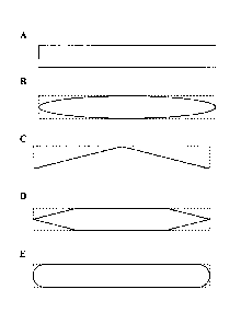
BRIEF DESCRIPTION OF THE DRAWINGS
FIG. 1 shows examples of cross sections of a number of embodiments of the
present
composite pellets having A) rectangular, B) elliptical, C) triangular, D)
hexagonal, and E)
oblate elliptical cross sectional shapes. In Figures 1(B) ¨ 1(E) the
rectangular envelope for
the particular cross sectional shape is shown in dashed lines.
DETAILED DESCRIPTION
[0009] FIGURE lA shows a die face cross-section of one embodiment of a
composite
pellet of the present application, where the shape and dimensions of the
pellet cross section
are derived from the extrusion die through which the material is extruded. The
thickness
("T") of the composite pellet is the narrow dimension of the perimeter of the
rectangle (i.e,
the height), and the width ("W") is the perpendicular and larger dimension of
the perimeter
of the rectangular envelope. The axial length ("L") of the composite pellet is
measured
along the axial direction of the extrusion. Suitable geometries for composite
pellets of the
present application are not limited to purely rectangular geometries, but also
include
generally flat ("substantially planar") cross-sectional geometries produced by
extrusion
through a suitably shaped orifice, including but not limited to the various
embodiments
shown in FIGURE 1.
[0010] The terms "controlled geometry pellet", "controlled geometry
micropellet",
"composite pellet", and "controlled aspect ratio pellets" are used in the
present application
interchangeably, and refer to a pellet of the present application.
-4-
CA 02756411 2011-09-23
WO 2010/132066
PCT/US2009/047983
[0011] The terms "particle" and "particulate" are used herein to describe
shaped materials
that are not a controlled geometry pellet but are of a size that would permit
incorporation
into a controlled geometry pellet, e.g., a material such as a carbon or glass
fiber.
[0012] The term "rectangular envelope" as used herein describes a rectangle
within which
another geometric shape, such as, for example, an ellipse, a triangle, a
hexagon, or an oblate
ellipse, can be inscribed such that the rectangle and the other geometric
cross-sectional
shape have the same aspect ratio. The rectangular envelope is drawn such that
the rectangle
has the thinnest possible shape, i.e., the width of the rectangle "W" is
minimized. The term
"rectangular envelope" may be used to characterize the cross-sectional shape
of a generally
planar face of the present controlled geometry pellets, e.g., to characterize
a die-face cross-
sectional shape of the present controlled geometry pellets.
[0013] The term "aspect ratio" may be used herein to refer to the ratio of the
width ("W")
of a pellet's cross-sectional rectangular envelope to its height ("T", i.e.,
the thickness of the
pellet's cross-sectional rectangular envelope), "W:T." Where the rectangular
envelope
refers to the cross-sectional shape of the face of the pellet of his ratio is
referred to herein as
the "cross-sectional aspect ratio."
[0014] The term "aspect ratio" may also be used to refer to the ratio of the
length of the
extruded pellet in the axial direction ("L"; i.e., the length in the direction
of the major axis
of the extruder) to width ("W") of a pellet's die cross-sectional rectangular
envelope. To
help avoid confusion this ratio, "L:W," may be referred to herein as the
"axial length/cross
sectional width ratio."
[0015] The term "die-face cross-sectional shape" may be used herein to refer
to the shape
of the pellet face(s) produced by extrusion through a suitably shaped orifice
¨ as opposed to
the shape of the pellet along its axial length, i.e., along the axial
direction of the extrusion.
[0016] The present composite pellets may have unique physical characteristics.
The
pellets can include a die-face cross-sectional shape having a rectangular
envelope with an
aspect ratio of at least about 1.5 and an axial length/cross sectional width
ratio of about 0.25
to 30. In some instances, the present composite pellets may have a die-face
cross-sectional
area of no more than about 5 mm2.
-5-
CA 02756411 2011-09-23
WO 2010/132066
PCT/US2009/047983
[0017] The present composite pellets may find utility in a variety of
applications. For
example, the pellets can be used in compression molding processes, where such
pellets can
provide an alternative to the use of thermoplastic polymer powders and
mixtures of
polymers powders with dry fibers. The present composite pellets can be used in
compression molding processes in conjunction with polymer powders. The
controlled
geometry pellets may be used to manufacture shaped articles with enhanced
physical
properties, such as, for example, impact strength, tensile strength, tensile
elongation, tensile
modulus, flexural strength and/or flexural modulus, superior to those of
similarly-shaped
articles formed either solely from polymer powders or mixtures of polymers
powders with
dry fibers with the same chemical composition as the pellets. The pellets may
also be
amenable to use in other processing methods including, for example, injection
molding and
extrusion operations. Other applications for composite pellets of the present
application can
include, for example, the use of composite pellets as color concentrates,
fragrance
concentrates, grinding or polishing media, or filter media.
[0018] The shape of the cross section of the pellets used for compression
molding can
affect the physical characteristics of the molded article as well as the ease
of processing.
For example, pellets having substantially rectangular cross-sections can be
well suited for
use in controlled geometry pellet ("CGP") compression molding operations,
i.e.,
compression molding carried out using composite pellets of the present
application.
[0019] Referring to FIGURE 1, examples of exemplary die cross sectional shapes
of
composite pellets of the present application that are A) rectangular, B)
elliptical, C)
triangular, D) hexagonal, and E) oblate elliptical are shown. The dashed lines
in FIGURES
1B-1E represent the perimeter of a rectangle that can envelop each of these
shapes, i.e., the
rectangular envelope. The rectangular envelope is identical for each shape, 1A-
1E, creating
a W:T ratio ("cross-sectional aspect ratio") of 8:1 for each of the cross-
sectional shapes
shown.
[0020] The composite pellets employed in the present compression molding
methods,
regardless of their specific cross sectional shape, commonly have a cross
sectional aspect
ratio (W:T) of at least about 1.5:1 and, typically no more than about 30:1. In
some
embodiments, the aspect ratio of W:T can be 2:1 to 15:1 or about 2:1 to 10:1.
In other
embodiments, the cross sectional aspect ratio of the pellets may be about 2:1
to 5:1.
-6-
CA 02756411 2011-09-23
WO 2010/132066
PCT/US2009/047983
Table 1.
Dimensions of Dies for
Preparation of Composite Pellets
Die Die Dimensions
Multi-Geometry
Rectangle 1 (R1) T = 1.07 mm W = 2.0 mm AL
= 0.76 - 2.3 mm
Rectangle 2 (R2) T = 1.07 mm W = 2.0 mm AL
= 0.76 - 2.3 mm
Rectangle 3 (R3) T = 1.07 mm W = 3.0 mm AL
= 0.76 - 2.3 mm
Rectangle 4 (R4) T = 1.07 mm W = 3.0 mm AL
= 0.76 - 2.3 mm
Circle 1 (C1) Diam. = 1.9 mm AL = 0.76 -
2.3 mm
Circle 2 (C2) Diam. = 1.9 mm AL = 0.76 -
2.3 mm
"T" hole Wl= 2.5 mm W2= 1.9 mm AL
= 0.76 - 2.3 mm
Other Dies
Rectangle 5 (R5) T = 1.1 mm W = 2.3 mm AL = 1.1 -2.3 mm
[0021] The axial length/cross sectional width ratio (L:W) of the present
pellets is often
desirably about 0.25:1 to 30:1. In some embodiments, the L:W may be 0.5:1 to
10:1.
Dimensions of exemplary rectangular dies suitable for use in forming the
present composite
pellets are among the various dies listed in Table 1.
[0022] A potential advantage of the above-described aspect ratios and
geometries for
composite pellets when used in compression molding may be that the pellets can
easily pack
together even with little or no agitation, pressure, or temperature applied.
When placed in a
container, such as a compression molding tool or other vessel, these materials
will typically
have a porosity of about 55% or less without the application of pressure or
elevated
temperatures. Due to this relatively low porosity when the material is
introduced into the
compression molding tool, less axial displacement of the two (or more) parts
of the tool is
commonly required. Reducing the axial displacement required for compaction
provides an
advantage not only in producing parts with lower porosity, but also in that it
can allow
larger parts to be produced on a given molding press as compared to
conventional
compression molding techniques, such as produced from powdered polymers and
blends of
powdered polymers with other fillers.
[0023] The "porosity" of a plurality of the present pellets in a container of
fixed
dimensions is a reflection of the capability of individual pellets to pack
closely together
without generating a large void volume. This capability can also be
characterized in terms
-7-
CA 02756411 2011-09-23
WO 2010/132066
PCT/US2009/047983
of the "compression factor" of the pellets. As used herein, the term
"compression factor"
refers to the ratio of initial to final volume when a 10" high volume of the
present
thermoplastic resin-based pellets are compression molded in a 4.5"OD x 3" ID
tubular
mold under a pressure of 170 bar (circa 2500 psi) at a temperature 20 C above
the melting
point of the thermoplastic resin. Thus, a compression factor of 3.3 (such as
typically
observed when powder forms of thermoplastic resins are employed in compression
molding
operations) would mean that the initial 10 inch high volume of pellets in the
mold was
compacted to form a roughly 3 inch high tubular article at the end of the
compression
molding operation under the conditions set forth above. The present controlled
geometry
pellets are often characterized by having a compression factor of no more than
about 2.5,
desirably no more than about 2.2 and, in some embodiments, no more than about
2Ø This
can permit parts of about 5 inches in height or higher to be produced from the
initial 10 inch
high volume of uncompressed pellets.
[0024] The use of the present controlled geometry pellets may include use in
compression
molding operations using pellets having a single cross sectional geometry. In
other
embodiments, pellets of such geometries may be employed in conjunction with
other pellet
geometries and/or particle geometries, regardless of whether the additional
pellet or particle
shapes meet the aspect ratio definitions described earlier. For instance, the
combination of
multiple sizes and/or shapes of controlled geometry pellets may perform as
well or better
than a single size or shape. Typically, at least about 40 wt.% and often 50
wt.% or more of
the thermoplastic composite material employed in a molding operation is
comprised of the
present controlled geometry pellets. This includes combining controlled
geometry pellets
with standard shaped pellets and/or powders, which may provide the same type
of benefits
as the exclusive use of controlled geometry pellets.
[0025] In some embodiments, the composite pellets can have a thickness ("T")
of about
0.005" to about 0.20" (circa 0.13 mm to 5 mm). In other embodiments, the
composite pellet
can have a thickness ("T") of about 0.010" to about 0.12" (about 0.25 mm to 3
mm), where
the length and width of the pellets conform to the aspect ratios described
above. Composite
pellets having a thickness of about 0.020" to 0.080" (about 0.5 mm to 2 mm)
are quite
commonly employed in the present compression molding operations.
[0026] To create a relatively short melting time for the controlled geometry
pellets, the
weight of the pellets may desirably be relatively low. For example, pellets
weighing no
-8-
CA 02756411 2011-09-23
WO 2010/132066
PCT/US2009/047983
more than about 30 mg may be quite suitable and, in many instances, the
present pellets
may weigh no more than about 10 mg. Pellets weighing 5 mg or less are often
quite
suitable for use in the present methods.
[0027] When fiber-reinforced controlled geometry pellets with the aspect ratio
defined in
this application are used to produce articles with fiber reinforcements, they
will have fiber
orientation predominantly, but not exclusively, in the length dimension of the
controlled
geometry pellets. When subsequently compression molded, the fiber direction
can be
predominantly in the plane perpendicular to the axial direction of
compression. In that
direction, the fibers can have an overall random orientation. This results in
articles of
manufacture with exceptional mechanical properties in that plane. By
controlling the
various aspect ratios of length, width, and thickness, the degree of
orientation can be
controlled and both mechanical properties and dimensional stability can be
tailored for
specific applications.
[0028] Despite one plane (the L:W plane) generally having the predominant
fiber
orientation, the overall random nature of the fiber alignment is believed to
result in articles
of manufacture with very good dimensional stability. The lower temperatures
and pressures
typically required to compression mold the present controlled geometry pellets
may also
provide additional benefit to dimensional stability in a variety of articles
of manufacture,
e.g., by reducing molded in stress. The compression molding operation may
suitably be
carried out under pressures in the range of about 1,500 to 20,000 psi.
[0029] Thermoplastic polymeric resins suitable for use in composite pellets of
the present
application include, for example, polyetheretherketone ("PEEK"),
polyetherimide ("PEI"),
polyethersulfone ("PES"), poly(arylene sulfide) ("PAS"), perfluoro alkyl vinyl
ether
("PFA"), polyethylene naphthalate ("PEN"); polyamideimide ("PAT"),
polyphthalamide
("PPA"), thermoplastic polyimide resin ("TPI"), polyether ketone ("PEK"),
polyetherketoneketone ("PEKK"), polyetherketoneetherketoneketone ("PEKEKK"),
polybenzimidazole ("PBI"), and mixtures of two or more of these resins. In
some
embodiments, the thermoplastic, organic polymer includes polyetheretherketone,
polyarylene sulfide, polyetherimide, or a blend of any two or more such
materials. For
example, the thermoplastic polymer may include an aromatic
polyetheretherketone, such as
an oxyaryloxyaryloxyaroyl type polyetheretherketone, e.g., an
oxyphenoxyphenoxybenzoyl
polyetheretherketone. PEEK and other poly arylether/arylketones (such as
polyetherketones
-9-
CA 02756411 2011-09-23
WO 2010/132066
PCT/US2009/047983
and polyetherketoneketones) are well known and are described in patents such
as EP 0 001
879, US 6,909,015, and US 6,274,770. In other embodiments, the polymeric resin
includes
polyarylene sulfide, e.g., polyphenylene sulfide ("PPS"), either alone or in
combination
with another thermoplastic polymeric resin(s). Other examples of suitable
resins include
thermoplastic polyolefins, such as polypropylene ("PP"), polyethylenes, e.g.,
high density
polyethylene ("HDPE") and ultrahigh molecular weight polyethylene ("UHMWPE"),
melt
processable fluoropolymers, such as perfluoro alkyl vinyl ethers ("PFA") and
ethylene
trifluoroethylene copolymers ("ETFE"), ethylene trichloroethylene ("ECTFE"),
polyethylene naphthalate, polyamideimide ("PAT"), polyphthalamide ("PPA"),
thermoplastic polyimide resin ("TPI"), polybenzimidazole ("PBI"), polyamides
(including
but not limited to nylon 6, nylon 6/6, nylon 11, nylon 12, nylon 6/12),
polycarbonates, and
polyesters (including but not limited to polyalkylene terephthalates, such as
polybutylene
terephthalate (PBT) and polyethylene terephthalate (PET)). The thermoplastic
resin may
include mixtures of two or more of the resins discussed above. In some
embodiments, the
thermoplastic, organic polymer includes polyetheretherketone, polyarylene
sulfide,
polyetherimide, or a blend of any two or more such materials. For example, the
thermoplastic polymer may include an aromatic polyetheretherketone such as
oxyaryloxyaryloxyaroyl polyetheretherketone, e.g., oxyphenoxyphenoxybenzoyl
polyetheretherketone. PEEK and other similar polyetherketones (such as
polyetherketoneketones) are well known and are described in patents such as EP
0001879,
US 6,909,015, and US 6,274,770. In other embodiments, the polymeric resin
includes
polyarylene sulfide, e.g., polyphenylene sulfide ("PPS"), either alone or in
combination
with another thermoplastic polymeric resin(s).
[0030] The thermoplastic polymeric resin may be present in the composite
pellets from
about 30 wt% to 98 wt% in some embodiments, from about 50 wt% to 95 wt% in
other
embodiments. In many embodiments, the composite material includes about 60 wt%
to 90
wt% of the thermoplastic polymeric resin or from about 60 wt% to 80 wt% in yet
other
embodiments.
-10-
CA 02756411 2011-09-23
WO 2010/132066
PCT/US2009/047983
[0031] In some embodiments, the thermoplastic polymer suitably includes a
polyetheretherketone (PEEK), such as an oxyphenoxyphenoxybenzoyl
polyetheretherketone, e.g., a polyetheretherketone, which includes oxy-1,4-
phenylene-oxy-
1,4-phenylene-carbony1-1,4-phenylene repeat units. Aromatic
polyetheretherketones, such
as oxyphenoxyphenoxybenzoyl polyetheretherketone, may typically be processed
via
extrusion at polymer temperatures of about 360 C to 400 C to form pellets. A
suitable
example of such polymers are commercially available as a powder and in a
number of other
grades and forms ranging from low medium and standard viscosity grades to easy
flow and
general purpose grades. PEEK polymers may be used in extrusion compounding and
commonly exhibits good wear resistance, low friction, and good chemical
resistance, such
as resistance to various fuels and other hydrocarbons.
[0032] In some embodiments, the composite pellets may include a blend of
thermoplastic
polymeric resin and reinforcing particulates. Reinforcing particulates, e.g.,
fibers or flakes,
suitable for use in composite pellets of the present application can include,
for example,
fibers or flakes formed from materials such as carbon, silicon, boron, aramid,
silicon oxide,
silicon carbide, silicon nitride, and/or alumina.
[0033] Reinforcing particulates in shapes such as, for example, fibers, milled
fibers,
whiskers, granules, grains, powders, or flakes can be used in compositions and
methods of
the present application. In some embodiments, reinforcing particulates can be
fibers. In
some embodiments, the fiber may be present in the composite pellets from 2 wt%
to about
60 wt%, from about 5 wt% to 50 wt% in other embodiments, or from about 10 wt%
to 40
wt%, in yet other embodiments. In some embodiments, the reinforcing
particulates can
suitably comprise glass fiber, carbon fiber (e.g., milled carbon fiber and/or
chopped carbon
fiber), or a combination thereof The glass fiber may also suitably include
milled and/or
chopped glass fiber. Other examples of suitable reinforcing particulates
include glass flakes
and/or glass spheres. In some embodiments, the milled carbon fiber can have a
diameter of
about 5 to 20 microns and an aspect ratio of about 5 to 50 and, in certain
embodiments,
about 10 to 30. In other embodiments, chopped carbon fibers can have a
diameter of about
to 20 microns and an aspect ratio of at least about 50, e.g., about 100 to
200. In still other
embodiments, the reinforcing particulates may include glass fibers (chopped
and/or milled
fibers), glass flakes and/or spherical glass particles. In some embodiments,
the reinforcing
particulates may desirably have a largest dimension which is no more than
about 90 % of
-11-
CA 02756411 2011-09-23
WO 2010/132066
PCT/US2009/047983
the largest pellet dimension. In certain embodiments, the reinforcing
particulates may
desirably have a largest dimension which is no more than about 90 % of the
width of the die
cross-sectional shape used to generate the pellet in an extrusion operation.
[0034] Methods of preparing the composite pellets are also provided. The
methods can
include blending the ingredients that will form the composite pellets, melting
the
thermoplastic component(s) and processing the resulting mixture containing the
molten
thermoplastic component(s) so as to wet out reinforcing particulates present
in the mixture
with the thermoplastic material. Such a processing operation typically results
in distributing
and dispersing reinforcing particulates in the thermoplastic component(s).
Such methods
may include blending the ingredients and extruding the mixture through a die
that produces
composite that is cut to provide composite pellets with a die cross-sectional
shape having a
rectangular envelope with an aspect ratio ("W:T") of at least about 1.5 and an
axial
length/cross sectional width ratio ("L:W") of about 0.25 to 30.
[0035] Alternatively, the methods may include several steps with the various
ingredients
being added at any given point in the process. For example, a first amount of
a
thermoplastic polymeric resin may be compounded with reinforcing particulates
in an
extruder to produce a first extrudate. The first extrudate may then be blended
with another
additive, such as, for example, a flame retardant, a lubricant, a conductive
additive
thermally and/or electrically conductive) a micro-tag, a colorant, or a
fragrance, and
subjected to a second extrusion to produce a second extrudate that is cut to
provide a
composite pellet with a cross-sectional shape having a rectangular envelope
with an aspect
ratio (W:T) of at least about 1.5 and an axial length/cross sectional width
ratio (L:W) of
about 0.25 to 30. Compounding may take place in a single screw, twin screw, or
other style
extruder. The methods may also include introducing the ingredients of any
particular stage
of the operation, e.g., prior to being fed to the extruder and/or at
intermediate stages of the
extrusion process.
[0036] In preparing the composite pellets, the same thermoplastic polymeric
resin may be
used in the preparation of both the first and second extrudates, or different
thermoplastic
polymeric resins may be used. If different thermoplastic polymers are used in
the steps,
they may be chemically distinct polymers, or just different grades of the same
polymer
having varying viscosities, melt indices, or other polymeric properties.
-12-
CA 02756411 2011-09-23
WO 2010/132066
PCT/US2009/047983
[0037] After molded articles have been formed from controlled geometry
pellets, the
molded articles can be machined by various methods known to one skilled in the
art, such
as, for example, drilling, turning, chip formation, and combinations of
machining methods.
[0038] The present invention, thus generally described, will be understood
more readily
by reference to the following examples, which are provided by way of
illustration and are
not intended to be limiting of the present invention.
EXPERIMENTAL
[0039] Materials. The carbon fiber ("CF") used to make the composites referred
to in the
following tables was a commercially available milled carbon fiber
approximately 5-10
microns in diameter and having an average length of about 100 to 300 microns,
i.e., having
an aspect ration of about 10 to 60. The polyetheretherketone ("PEEK") used in
the
experimental trials referred to in the following tables was a commercially
available
phenoxyphenoxybenzoyl polyetheretherketone. Extruded compositions were
prepared by
compounding the PEEK with the carbon fiber in a single or twin screw extruder
to form 30
wt.% CF in PEEK pellets of the indicated size and shape. After extrusion
through dies
similar to the geometry described in Table 1 and cooling, the compounded
materials, were
cut to the desired length, e.g., pellets with an axial dimension ("axial
length") of about 0.75
to 2.5 mm.
Table 2.
Physical Properties - Compression Molded Articles
Property ASTM 30% Carbon 30% Dry CF Commercial
TEST Fiber PEEK ¨ Mix w/ Improvement PEEK Pellets Improvement
CGP* PEEK Powder w/ w/ w/
30% CF
Compression Compression CGP Extrusion CGP
Molded Molded Technology
Technology
Specific D972 1.41 1.42 1.41
gravity
Impact D256 1.55 ft-Lb/in 1.03 ft-Lb/in 49.8%
1.12 ft-Lb/in 38.3%
Strength Izod
Notched 1/8"
-13-
CA 02756411 2011-09-23
WO 2010/132066 PCT/US2009/047983
Tensile D638 19,475 14,000 39.0% 19,000 2.5%
Strength
Tensile D638 5.93 2 195.0% 5 18.6%
Elongation
Tensile D638 2,078,550 800,000 159.0% 1,100,000 88.0%
Modulus
Flexural D790 35,631 30,000 18.7% 25,750 38.0%
Strength
Flexural D790 1,327,247 1,300,000 2.0% 1,250,000
6.0%
Modulus
Volume D257 1E5 ohm.cm 1E5 ohm.cm 1E5 ohm.cm --
Resistivity
Deflection D648 600 F 450 F + 150 F 518 F + 132 F
Temperature
Flammability D3801 V-0 g1/16 in V-0 g1/16 in V-0 g1/16 in
* CGP - "controlled geometry pellets".
[0040] The results of various tests of physical properties of compression
molded articles
prepared with 30% CF/PEEK controlled geometry pellets (shown in Table 2) are
compared
to tests of the physical properties for articles prepared from PEEK by (a)
compression
molding a mixture of a powdered form of PEEK with 30% dry CF and (b) extrusion
of
standard cylindrical shaped 30% CF/PEEK pellets. The articles materials formed
from the
present controlled geometry pellets were prepared from CF/PEEK composite
pellets having
the cross sectional geometries listed in Table 1.
[0041] The PEEK controlled geometry pellets can be compression molded,
injection
molded, and extruded to form stock shapes. These positive characteristics
allow for a
processor with multiple processes to simplify their inventory management.
Furthermore, in
compression molding with the controlled geometry pellets, the need for mixing
powder
resins with reinforcing fillers as a separate manufacturing step is
eliminated, as the
controlled geometry pellets are provided to the customer already melt
compounded. The
controlled geometry pellets can also be dried more effectively in desiccant
hopper dryers
utilizing forced convection, a process that cannot be used with polymer
powder/fiber
mixtures which must instead be dried in ovens with little to no convection
that do not
remove as much moisture as the forced convection dryers. The better-dried
controlled
geometry pellets can eliminate incidences of porosity due to humidity being
trapped in the
powdered blends, humidity not present in micro pellets dried in desiccant
dryers; this
effectively increases yield and economics in the compression molding of
shapes.
-14-
CA 02756411 2011-09-23
WO 2010/132066
PCT/US2009/047983
[0042] Typical compression molding grade compounds are powder mechanical
blends
blended in high intensity mixers. When powder resin/dry fiber mixtures are
used, the
polymer and fibrous reinforcements are wetted only during the compression
molding
process when the polymer melts, thus not providing effective and complete
fiber or filler
wet out which is crucial for obtaining uniform properties of the molded
article. Powdered
blends yields lower mechanical strength than melt compounded controlled
geometry pellets.
Furthermore due to the fact that the powdered blends are a mechanical blend
the compounds
suffer from settling and ingredient separation during transportation,
warehouse operations
and prior to the molding process taking place. This forces the user of the
powdered blends
to have to re-blend the compounds just prior to drying and molding; controlled
geometry
pellets of the present application eliminate this step, further reducing
manufacturing costs.
An issue of rejected moldings due to ingredient separation and/or migration
can often be
totally eliminated using the present controlled geometry pellets, thus
increasing yield.
[0043] High performance thermoplastic stock shapes compression molded from
controlled
geometry pellets can reduce the cost of manufacturing, increase yield and
result in higher
properties due to the fibers being pre-wetted with polymer before the actual
compression
molding process. Articles formed by compression molding the present controlled
geometry
pellets can provide an increase in tensile and flexural properties of more
than 50% when
compared to the same product when molded from a typical powdered blend, as
shown in
Table 2. The compression molded PEEK controlled geometry pellets can have
mechanical
properties as good as or better than extruded shapes. This is a novelty since
extruded shapes
normally would have higher mechanical properties than compression molded
shapes. This
demonstrates the potential advantages of controlled geometry pellets.
Properties observed
in compression molded articles prepared by two different groups with two
different
compression molding techniques exhibited very similar properties with only
slight statistical
variation, demonstrating a very uniform product more forgiving than articles
formed from
powdered thermoplastic blends.
[0044] The pellets can also be injection molded with lower stock temperatures
as the
pellets offer faster screw recovery of the injection molding machine. The
controlled
geometry pellets can be made with relatively smaller milled fibers, this and
the lower stock
temperatures produce injection molded shapes with much lower stress than
shapes molded
with standard pellets. The benefit of this is that the pellets can allow for
the machining and
-15-
CA 02756411 2011-09-23
WO 2010/132066
PCT/US2009/047983
fabrication of very tight tolerance components that do not twist or change
dimensions
during machining and during service. This can also apply to extruded shapes
manufactured
from the present pellets.
[0045] Compression molded shapes made from controlled geometry pellets can
exhibit
higher mechanical strength this allowing for the use of compression molded
shapes of
PEEK in applications not previously possible with molded shapes derived from
powdered
blends, such as in the case of PEEK-based turbo compressor labyrinth seals
requiring higher
performance for service temperatures above 350 F.
Illustrative Embodiments
[0046] Reference is made in the following to illustrative embodiments of the
subject
matter described herein. The following embodiments describe illustrative
embodiments that
may include various features, characteristics, and advantages of the subject
matter as
presently described. Accordingly, the following embodiments should not be
considered as
being comprehensive of all of the possible embodiments or otherwise limit the
scope of the
methods materials and coatings described herein.
[0047] One embodiment provides composite pellets comprising thermoplastic
polymeric
resin and reinforcing particulates having a largest dimension which is no more
than about
90 % of the largest pellet dimension. The composite pellets may have a cross
sectional
shape having a rectangular envelope with an aspect ratio (W:T) of at least
about 1.5 and an
axial length/cross sectional width ratio (L:W) of about 0.25 to 30. The
composite pellets
can have a thickness of about 0.1 to 8 mm (circa 0.5 ¨ 3 mm). The composite
pellets may
have a cross sectional shape having a rectangular envelope with an aspect
ratio of about 1.5
to 10 and an axial length/cross sectional width ratio of about 0.25 to 5. The
composite
pellets may have a cross sectional shape having a rectangular envelope with an
aspect ratio
of about 2 to 5 and an axial length/cross sectional width ratio of about 0.5
to 3. The
composite pellets often have a substantially rectangular cross sectional
shape. In other
embodiments, the composite pellets may have a flattened triangular cross
sectional shape, a
flattened hexagonal cross sectional shape and/or an elliptical cross sectional
shape. In
certain instances, the pellets have an average weight of about 1 to 20 mg and,
often, no
more than about 10 mg. Such pellets may have a rectangular cross sectional
shape with an
aspect ratio of about 2 to 5; an axial length/cross sectional width ratio of
about 0.5 to 2; a
thickness of about 0.5 to 2 mm; a width of about 1 to 5 mm; and/or an axial
length of about
-16-
CA 02756411 2011-09-23
WO 2010/132066
PCT/US2009/047983
1 to 5 mm. Such composite pellets typically comprise about 50 to 90 wt.% of
the
thermoplastic polymeric resin; and about 10 to 50 wt.% of the reinforcing
particulates. The
reinforcing particulates comprise fibers may have an average length of about
0.05 to 3 mm.
In many embodiments, the composite pellets have a compression factor of no
more than
about 2.2 and the compression factor may be 2.0 or less.
[0048] Composite pellets comprising thermoplastic polymeric resin; and
reinforcing
particulates having a largest dimension which is no more than about 90% of the
largest
pellet dimension; wherein the composite pellets have a cross sectional shape
having a
rectangular envelope with an aspect ratio (W:T) of at least about 1.5 and an
axial
length/cross sectional width ratio (L:W) of about 0.25 to 30, more commonly
about 0.25 to
5. The thermoplastic resin-based material may comprise at least about 60 wt.%
polyetheretherketone, polyetherimide, polyethersulfone or a combination
thereof In some
embodiments, the controlled geometry pellets may have an axial length of no
more than
about 5 mm and a thickness of about 0.25 mm to 3 mm.
[0049] Composite pellets comprising thermoplastic polymeric resin; and a
plurality of
randomly oriented reinforcing fibers; wherein the composite pellets have a
thickness of no
more than about 2 mm; a cross sectional shape having a rectangular envelope
with an aspect
ratio (W:T) of at least about 1.5; and an axial length/cross sectional width
ratio (L:W) of
about 0.5 to 3. The thermoplastic polymeric resin may include PEEK, PEI, PES,
PPS, PAS
or a blend of two or more thereof
[0050] Composite pellets comprising about 50 to 90 wt.% thermoplastic
polymeric resin;
and about 10 to 50 wt.% of a plurality of randomly oriented reinforcing
fibers; wherein the
composite pellets have a compression factor of no more than about 2.2; a cross
sectional
shape having a rectangular envelope with an aspect ratio (W:T) of at least
about 1.5; and a
thickness of about 0.5 to 2 mm. The thermoplastic polymeric resin may include
PEEK, PEI,
PES, PPS, PAS or a blend of two or more thereof The randomly oriented
reinforcing fibers
may include milled and/or chopped carbon fibers.
[0051] In one exemplary embodiment, the thermoplastic composite material
includes a
plurality of controlled geometry pellets, which include thermoplastic organic
polymer and a
plurality of carbon fibers. The composite pellets exhibit a compression factor
of no more
than about 2.5. The thermoplastic composite material may include about 60 to
80 wt.%
-17-
CA 02756411 2011-09-23
WO 2010/132066
PCT/US2009/047983
phenoxyphenoxybenzoyl polyetheretherketone as the thermoplastic organic
polymer
component. In other embodiments, the thermoplastic composite material may
include
about 60 to 80 wt.% of a blend of phenoxyphenoxybenzoyl polyetheretherketone
with one
or more other organic thermoplastic polymers.
[0052] In some embodiments, the thermoplastic, organic polymer includes
polyetheretherketone, polyarylene sulfide, polyetherimide, or a blend of any
two or more
such materials. For example, the thermoplastic polymer may include an aromatic
polyetheretherketone such as aryloxyaryloxyaroyl polyetheretherketone, e.g.,
4-(4-phenoxyphenoxy) benzoyl polyetheretherketone. In some embodiments, the
thermoplastic polymer may include polyarylene sulfide, such as polyphenylene
sulfide,
either alone or in combination with one or more other thermoplastic polymers,
e.g.,
polyetheretherketone.
[0053] Another embodiment provides a method of manufacturing a shaped article
comprising: compression molding thermoplastic resin-based material to provide
a molded
article; wherein the thermoplastic resin-based material comprises a plurality
of controlled
geometry pellets, which include thermoplastic polymeric resin and reinforcing
particulates;
the pellets having an axial length of no more than about 5 mm and a cross
sectional shape
having a rectangular envelope with an aspect ratio of at least about 1.5. The
reinforcing
particulates commonly have a largest dimension which is no more than about 90%
of the
largest pellet dimension.
[0054] Another embodiment provides a method of manufacturing a shaped article
comprising: compression molding thermoplastic resin-based material to provide
a molded
article; wherein the thermoplastic resin-based material comprises a plurality
of controlled
geometry pellets, which include thermoplastic polymeric resin. The pellets may
having an
axial length of no more than about 5 mm and a cross sectional shape having a
rectangular
envelope with an aspect ratio of at least 1.5 and, in some instances about 2
to 10. The
controlled geometry pellets may also comprise a plurality of reinforcing
particulates, e.g., a
plurality of randomly oriented glass and/or carbon fibers.
[0055] Another embodiment provides a method of manufacturing a shaped article
comprising: compression molding thermoplastic resin-based material to provide
a molded
article. The thermoplastic resin-based material has a compression factor of no
more than
-18-
CA 02756411 2011-09-23
WO 2010/132066
PCT/US2009/047983
about 2.2 and comprises a plurality of controlled geometry pellets, which
include
thermoplastic polymeric resin and reinforcing particulates. The pellets have a
cross
sectional shape having a rectangular envelope with an aspect ratio of at least
1.5. The
reinforcing particulates have a largest dimension which is no more than about
90 % of the
largest let dimension. The thermoplastic polymeric resin typically comprises
polyetheretherketone, polyetherimide, polyethersulfone, polyarylenesulfide
and/or,
polyphthalamide. The controlled geometry pellets commonly have an average
weight of
about 1 to 20 mg; and often may have a substantially rectangular cross
sectional shape with
an aspect ratio of about 2 to 5. The pellets may have an axial length/cross
sectional width
ratio of about 0.75 to 2 and a thickness of about 0.5 to 2 mm. Such pellets
may have a
width of about 1 to 5 mm and an axial length of about 1 to 5 mm.
[0056] Other embodiments are directed to shaped articles formed by the
compression
molding methods described herein. Such shaped articles can have an Izod impact
strength
(notched 1/8") that is at least about 20% higher than a compression molded or
extruded
article prepared from a corresponding polymer powder and reinforcing fibers.
The present
compression molded article can have a tensile strength that is at least about
20% higher than
a compression molded article prepared from a corresponding polymer powder and
reinforcing fibers. The present compression molded article can have a tensile
elongation
that is at least about 50% higher than a compression molded article prepared
from a
corresponding polymer powder and reinforcing fibers; and at least about 10%
higher than an
article formed by extruding a corresponding polymer and reinforcing fiber
mixture. The
present compression molded article can have a tensile modulus that is at least
about 50%
higher than a compression molded or extruded article prepared from a
corresponding
polymer powder and reinforcing fibers. The present compression molded article
can have a
flexural strength that is at least about 10% higher than a compression molded
or extruded
article prepared from a corresponding polymer powder and reinforcing fibers.
[0057] Another embodiment provides composite pellets comprising thermoplastic
polymeric resin and reinforcing particulates having a largest dimension which
is no more
than about 90 % of the largest pellet dimension. The composite pellets have a
cross
sectional shape having a rectangular envelope with an aspect ratio (W:T) of
about 2 to 10
and an axial length/cross sectional width ratio (L:W) of about 0.5 to 3. The
composite
pellets have a compression factor of no more than about 2.2. The pellets may
have a
-19-
CA 02756411 2011-09-23
WO 2010/132066
PCT/US2009/047983
thickness of about 0.25 to 2 mm and a length of no more than about 3 mm. The
pellets
typically include 50 to 90 wt.% thermoplastic polymeric resin; and about 10 to
50 wt.% of a
plurality of randomly oriented reinforcing fibers. The thermoplastic polymeric
resin
commonly comprises polyetheretherketone, polyetherimide, polyethersulfone,
polyarylenesulfide, polyphthalamide or a combination thereof The randomly
oriented
reinforcing fibers may include carbon fibers, e.g., milled and/or chopped
fibers. Such fibers
may have a diameter of about 5 to 20 microns and an aspect ratio of about 10
to 200.
[0058] In certain embodiments, the composite pellets may suitably have a
rectangular box
shape (i.e., a right rectangular prism or cuboid shape). Such composite
pellets may have at
least two opposing generally flat faces, which have a rectangular cross
sectional shape with
an aspect ratio of at least about 1.5. The other faces of the rectangular box
shape may have
a rectangular cross sectional shape with a similar aspect ratio. In some
instances, one or
more pairs of opposing faces may have a substantially square cross sectional
shape. Such
pellets may comprise thermoplastic polymeric resin and reinforcing
particulates having a
largest dimension which is no more than about 90 % of the largest pellet
dimension. In
some embodiments, the reinforcing particulates may be fibers, which have a
length which is
no more than about 90% of the width of the orifice in the die employed to
produce such
pellet in an extrusion operation.
[0059] Another embodiment provides extruded composite pellets which include
thermoplastic polymeric resin and a plurality of reinforcing particulates
dispersed in the
thermoplastic polymeric resin. The composite pellet has at least three
substantially planar
faces and has an axial length which is no more than about 50% of the largest
die-face cross
sectional dimension. The reinforcing particulates typically have a largest
dimension which
is no more than about 90 % of the largest pellet dimension.
[0060] Another embodiment provides composite pellets which have a rectangular
box
shape with at least two opposing faces having an aspect ratio of at least
about 1.5,
commonly 2 or higher, and often desirably about 2 to 5. The composite pellets
include
thermoplastic polymeric resin and a plurality of reinforcing particulates
dispersed in the
thermoplastic polymeric resin. The reinforcing particulates generally have a
largest
dimension which is no more than about 90% of the largest pellet dimension.
-20-
CA 02756411 2011-09-23
WO 2010/132066
PCT/US2009/047983
[0061] For the purposes of this disclosure and unless otherwise specified, "a"
or "an"
means "one or more." The word "or" when used without a preceding "either" (or
other
similar language indicating that "or" is unequivocally meant to be exclusive ¨
e.g., only
one of x or y, etc.) shall be interpreted to be inclusive, that is "or" when
it appears alone
shall mean both "and" and "or." Likewise, as used herein, the term "and/or"
shall also be
interpreted to be inclusive in that the term shall mean both "and" and "or."
In situations
where "and/or" or "or" are used as a conjunction for a group of three or more
items, the
group should be interpreted to include one item alone, all of the items
together, or any
combination or number of the items. Terms used in the specification and claims
such as
have, having, include, and including should be construed to be synonymous with
the terms
comprise and comprising.
[0062] As used herein, "about" will be understood by persons of ordinary skill
in the art
and will vary to some extent depending upon the context in which it is used.
From about X
to Y is intended to mean from about X to about Y, where X and Y are the
specified values.
[0063] One skilled in the art will readily realize that all ranges discussed
can and do
necessarily also describe all subranges therein for all purposes and that all
such subranges
also form part and parcel of this invention.
[0064] While several, non-limiting examples have been illustrated and
described, it should
be understood that changes and modifications can be made therein in accordance
with
ordinary skill in the art without departing from the invention in its broader
aspects as
defined in the following claims.
-21-