Note: Descriptions are shown in the official language in which they were submitted.
CA 02757173 2015-04-24
51050-150
SYSTEMS AND METHODS FOR APPLYING MODEL TRACKING TO MOTION
CAPTURE
BACKGROUND
[0001] Many computing applications such as computer games, multimedia
applications, or the like include avatars or characters that are animated
using typical
motion capture techniques. For example, when developing a golf game, a
professional
golfer may be brought into a studio having motion capture equipment including,
for
example, a plurality of cameras directed toward a particular point in the
studio. The
professional golfer may then be outfitted in a motion capture suit having a
plurality of
point indicators that may be configured with and tracked by the cameras such
that the
cameras may capture, for example, golfing motions of the professional golfer.
The
motions can then applied to an avatar or character during development of the
golf game.
Upon completion of the golf game, the avatar or character can then be animated
with the
motions of the professional golfer during execution of the golf game.
Unfortunately,
typical motion capture techniques are costly, tied to the development of a
specific
application, and do not include motions associated with an actual a player or
user of the
application.
SUMMARY
[0002] Disclosed herein are systems and methods for capturing motions of a
user
in a scene. For example, an image such as depth of a scene may be received or
observed.
The depth image may then be analyzed to determine whether the image includes a
human
target associated with a user. If the image includes a human target associated
with a user,
a model of the user may be generated. The model may then be tracked in
response to
movement of the user such that the model may be adjusted to mimic the movement
of the
user. For example, the model may be a skeletal model having joints and bones
that may
be adjusted into poses corresponding to the movement of the user in physical
space.
According to an example embodiment, a motion capture file of the movement of
the user
may then be generated in real-time based on the tracked model. For example, a
set of
vectors that define the joints and bones for each of the poses of the adjusted
model may be
captured and rendered in the motion capture file.
- 1 -
CA 02757173 2016-09-16
51050-150
[0002a] According to one aspect of the present invention, there is provided a
method of creating a model of a user in a scene, the method comprising:
receiving, by a
computer, a depth image of a scene; identifying, by the computer, an object in
the depth
image; comparing, by the computer, the object to a pattern; isolating, by the
computer, the
object in response to determining that the object is associated with the
pattern; measuring, by
the computer, body parts of the isolated object; generating, by the computer,
a data structure
comprising one or more vectors, each vector representing at least one joint or
bone of the
isolated object in the data structure, the at least one joint or bone
determined based at least in
part on the measuring and corresponding to a body part of the user; capturing
movement of at
least the body part of the user over time in a motion capture file as movement
of the data
structure based on movements of the user corresponding to a designated user
motion, the data
structure including vectors including X, Y, and Z values that define the
joints and bones of the
isolated object in the data structure at various points in time as the user
moves the isolated
object to perform the designated user motion; detecting that the user has
performed a gesture
associated with the designated user motion, said gesture indicating that the
user desires an
avatar or game character to perform the designated user motion; and in
response to detecting
said gesture, applying one or more motion captures in the motion capture file
to an avatar or
game character corresponding to the user in the scene, wherein the avatar or
game character is
animated by the motion captures to mimic the designated user motion performed
by the user
by moving corresponding body parts of the avatar or game character
corresponding to the
body parts of the user in the scene.
[000213] According to another aspect of the present invention, there is
provided
a system for creating a model of a user in a scene, comprising: a processor;
and a memory
communicatively coupled to the processor when the system is operational, the
memory
bearing processor-executable instructions that, when executed on the
processor, cause the
system at least to: receive a depth image of a scene; identify an object in
the depth image;
compare the object to a pattern; isolate the object in response to determining
that the object is
associated with the pattern; measure body parts of the isolated object;
generate a data structure
comprising one or more vectors, each vector representing at least one joint or
bone of the
- la-
CA 02757173 2016-09-16
51050-150
isolated object in the data structure, the at least one joint or bone
determined based at least in
part on the measurement and corresponding to a body part of the user; capture
movement of at
least the body part of the user over time in a motion capture file as movement
of the data
structure based on movements of the user corresponding to a designated user
motion, the data
structure including vectors including X, Y, and Z values that define the
joints and bones of the
isolated object in the data structure at various points in time as the user
moves the isolated
object to perform the designated user motion; detect that the user has
performed a gesture
associated with the designated user motion, said gesture indicating that the
user desires an
avatar or game character to perform the designated user motion; and in
response to detecting
said gesture, apply one or more motion captures in the motion capture file to
an avatar or
game character corresponding to the user in the scene, wherein the avatar or
game character is
animated by the motion captures to mimic the designated user motion performed
by the user
by moving corresponding body parts of the avatar or game character
corresponding to the
body parts of the user in the scene.
[0002c] According to still another aspect of the present invention, there is
provided a computer-readable memory device that stores computer-executable
instructions for
creating a model of a user in a scene when said computer-executable
instructions are executed
on a computer, by causing the computer at least to: receive a depth image of a
scene; identify
an object in the depth image; compare the object to a pattern; isolate the
object in response to
determining that the object is associated with the pattern; measure body parts
of the isolated
object; generate a data structure comprising one or more vectors, each vector
representing at
least one joint or bone of the isolated object in the data structure, the at
least one joint or bone
determined based at least in part on the measurement and corresponding to a
body part of the
user; capture movement of at least the body part of the user over time in a
motion capture file
as movement of the data structure based on movements of the user corresponding
to a
designated user motion, the data structure including vectors including X, Y,
and Z values that
define the joints and bones of the isolated object in the data structure at
various points in time
as the user moves the isolated object to perform the designated user motion;
detect that the
user has performed a gesture associated with the designated user motion, said
gesture
- lb -
CA 02757173 2016-09-16
51050-150
indicating that the user desires an avatar or game character to perform the
designated user
motion; and in response to detecting said gesture, apply one or more motion
captures in the
motion capture file to an avatar or game character corresponding to the user
in the scene,
wherein the avatar or game character is animated by the motion captures to
mimic the
designated user motion performed by the user by moving corresponding body
parts of the
avatar or game character corresponding to the body parts of the user in the
scene.
[0003] This Summary is provided to introduce a selection of concepts in a
simplified form that are further described below in the Detailed Description.
This Summary is
not intended to identify key features or essential features of the claimed
subject matter, nor is
it intended to be used to limit the scope of the claimed subject
- 1 c -
CA 02757173 2011 09 29
WO 2010/126816 PCT/US2010/032366
matter. Furthermore, the claimed subject matter is not limited to
implementations that
solve any or all disadvantages noted in any part of this disclosure.
BRIEF DESCRIPTION OF THE DRAWINGS
[0004] FIGs. lA and 1B illustrate an example embodiment of a target
recognition, analysis, and tracking system with a user playing a game.
[0005] FIG. 2 illustrates an example embodiment of a capture device that may
be
used in a target recognition, analysis, and tracking system.
[0006] FIG. 3 illustrates an example embodiment of a computing environment
that may be used to interpret one or more gestures in a target recognition,
analysis, and
tracking system and/or animate an avatar or on-screen character displayed by a
target
recognition, analysis, and tracking system.
[0007] FIG. 4 illustrates another example embodiment of a computing
environment that may be used to interpret one or more gestures in a target
recognition,
analysis, and tracking system and/or animate an avatar or on-screen character
displayed by
a target recognition, analysis, and tracking system.
[0008] FIG. 5 depicts a flow diagram of an example method for capturing motion
of a human target.
[0009] FIG. 6 illustrates an example embodiment of a image that may include a
human target.
[0010] FIG. 7 illustrates an example embodiment of a model that may be
generated for a human target.
[0011] FIGs. 8A-8C illustrate an example embodiment of a model that may be
captured at various points in time.
[0012] FIGs. 9A-9C illustrate an example embodiment of an avatar or game
character that may be animated based on a model that may be captured at
various points in
time.
DETAILED DESCRIPTION OF ILLUSTRATIVE EMBODIMENTS
[0013] As will be described herein, a user may control an application
executing
on a computing environment such as a game console, a computer, or the like
and/or may
animate an avatar or on-screen character by performing one or more gestures
and/or
movements. According to one embodiment, the gestures and/or movements may be
received by, for example, a capture device. For example, the capture device
may capture a
depth image of a scene. In one embodiment, the capture device may determine
whether
one or more targets or objects in the scene corresponds to a human target such
as the user.
- 2 -
CA 02757173 2011 09 29
WO 2010/126816 PCT/US2010/032366
Each target or object that matches the corresponds to a human target may then
be scanned
to generate a model such as a skeletal model, a mesh human model, or the like
associated
therewith. The model may then be provided to the computing environment such
that the
computing environment may track the model, generate a motion capture file of
the tracked
model, render an avatar associated with the model, animate an avatar based on
the motion
capture file of the tracked model, and/or determine which controls to perform
in an
application executing on the computer environment based on, for example, the
tracked
model.
[0014] FIGs. lA and 1B illustrate an example embodiment of a configuration of
a target recognition, analysis, and tracking system 10 with a user 18 playing
a boxing
game. In an example embodiment, the target recognition, analysis, and tracking
system 10
may be used to recognize, analyze, and/or track a human target such as the
user 18.
[0015] As shown in FIG. 1A, the target recognition, analysis, and tracking
system 10 may include a computing environment 12. The computing environment 12
may
be a computer, a gaming system or console, or the like. According to an
example
embodiment, the computing environment 12 may include hardware components
and/or
software components such that the computing environment 12 may be used to
execute
applications such as gaming applications, non-gaming applications, or the
like. In one
embodiment, the computing environment 12 may include a processor such as a
standardized processor, a specialized processor, a microprocessor, or the like
that may
execute instructions including, for example, instructions for receiving an
image,
generating a model of a user captured in the image, tracking the model,
generating a
motion capture file based on the tracked model, applying the motion capture
file, or any
other suitable instruction, which will be described in more detail below.
[0016] As shown in FIG. 1A, the target recognition, analysis, and tracking
system 10 may further include a capture device 20. The capture device 20 may
be, for
example, a camera that may be used to visually monitor one or more users, such
as the
user 18, such that gestures and/or movements performed by the one or more
users may be
captured, analyzed, and tracked to perform one or more controls or actions
within an
application and/or animate an avatar or on-screen character, as will be
described in more
detail below.
[0017] According to one embodiment, the target recognition, analysis, and
tracking system 10 may be connected to an audiovisual device 16 such as a
television, a
monitor, a high-definition television (HDTV), or the like that may provide
game or
- 3 -
CA 02757173 2011 09 29
WO 2010/126816 PCT/US2010/032366
application visuals and/or audio to a user such as the user 18. For example,
the computing
environment 12 may include a video adapter such as a graphics card and/or an
audio
adapter such as a sound card that may provide audiovisual signals associated
with the
game application, non-game application, or the like. The audiovisual device 16
may
receive the audiovisual signals from the computing environment 12 and may then
output
the game or application visuals and/or audio associated with the audiovisual
signals to the
user 18. According to one embodiment, the audiovisual device 16 may be
connected to
the computing environment 12 via, for example, an S-Video cable, a coaxial
cable, an
HDMI cable, a DVI cable, a VGA cable, or the like.
[0018] As shown in FIGs. lA and 1B, the target recognition, analysis, and
tracking system 10 may be used to recognize, analyze, and/or track a human
target such as
the user 18. For example, the user 18 may be tracked using the capture device
20 such
that the gestures and/or movements of user 18 may be captured to animate an
avatar or on-
screen character and/or may be interpreted as controls that may be used to
affect the
application being executed by computer environment 12. Thus, according to one
embodiment, the user 18 may move his or her body to control the application
and/or
animate the avatar or on-screen character.
[0019] As shown in FIGs. lA and 1B, in an example embodiment, the
application executing on the computing environment 12 may be a boxing game
that the
user 18 may be playing. For example, the computing environment 12 may use the
audiovisual device 16 to provide a visual representation of a boxing opponent
38 to the
user 18. The computing environment 12 may also use the audiovisual device 16
to
provide a visual representation of a player avatar 40 that the user 18 may
control with his
or her movements. For example, as shown in FIG. 1B, the user 18 may throw a
punch in
physical space to cause the player avatar 40 to throw a punch in game space.
Thus,
according to an example embodiment, the computer environment 12 and the
capture
device 20 of the target recognition, analysis, and tracking system 10 may be
used to
recognize and analyze the punch of the user 18 in physical space such that the
punch may
be interpreted as a game control of the player avatar 40 in game space and/or
the motion of
the punch may be used to animate the player avatar 40 in game space.
[0020] Other movements by the user 18 may also be interpreted as other
controls
or actions and/or used to animate the player avatar, such as controls to bob,
weave, shuffle,
block, jab, or throw a variety of different power punches. Furthermore, some
movements
may be interpreted as controls that may correspond to actions other than
controlling the
- 4 -
CA 02757173 2011 09 29
WO 2010/126816 PCT/US2010/032366
player avatar 40. For example, the player may use movements to end, pause, or
save a
game, select a level, view high scores, communicate with a friend, etc.
Additionally, a full
range of motion of the user 18 may be available, used, and analyzed in any
suitable
manner to interact with an application.
[0021] In example embodiments, the human target such as the user 18 may have
an object. In such embodiments, the user of an electronic game may be holding
the object
such that the motions of the player and the object may be used to adjust
and/or control
parameters of the game. For example, the motion of a player holding a racket
may be
tracked and utilized for controlling an on-screen racket in an electronic
sports game. In
another example embodiment, the motion of a player holding an object may be
tracked
and utilized for controlling an on-screen weapon in an electronic combat game.
[0022] According to other example embodiments, the target recognition,
analysis, and tracking system 10 may further be used to interpret target
movements as
operating system and/or application controls that are outside the realm of
games. For
example, virtually any controllable aspect of an operating system and/or
application may
be controlled by movements of the target such as the user 18.
[0023] FIG. 2 illustrates an example embodiment of the capture device 20 that
may be used in the target recognition, analysis, and tracking system 10.
According to an
example embodiment, the capture device 20 may be configured to capture video
with
depth information including a depth image that may include depth values via
any suitable
technique including, for example, time-of-flight, structured light, stereo
image, or the like.
According to one embodiment, the capture device 20 may organize the depth
information
into "Z layers," or layers that may be perpendicular to a Z axis extending
from the depth
camera along its line of sight.
[0024] As shown in FIG. 2, the capture device 20 may include an image camera
component 22. According to an example embodiment, the image camera component
22
may be a depth camera that may capture the depth image of a scene. The depth
image
may include a two-dimensional (2-D) pixel area of the captured scene where
each pixel in
the 2-D pixel area may represent a depth value such as a length or distance
in, for
example, centimeters, millimeters, or the like of an object in the captured
scene from the
camera.
[0025] As shown in FIG. 2, according to an example embodiment, the image
camera component 22 may include an IR light component 24, a three-dimensional
(3-D)
camera 26, and an RGB camera 28 that may be used to capture the depth image of
a scene.
- 5 -
CA 02757173 2011 09 29
WO 2010/126816 PCT/US2010/032366
For example, in time-of-flight analysis, the IR light component 24 of the
capture device 20
may emit an infrared light onto the scene and may then use sensors (not shown)
to detect
the backscattered light from the surface of one or more targets and objects in
the scene
using, for example, the 3-D camera 26 and/or the RGB camera 28. In some
embodiments,
pulsed infrared light may be used such that the time between an outgoing light
pulse and a
corresponding incoming light pulse may be measured and used to determine a
physical
distance from the capture device 20 to a particular location on the targets or
objects in the
scene. Additionally, in other example embodiments, the phase of the outgoing
light wave
may be compared to the phase of the incoming light wave to determine a phase
shift. The
phase shift may then be used to determine a physical distance from the capture
device to a
particular location on the targets or objects.
[0026] According to another example embodiment, time-of-flight analysis may
be used to indirectly determine a physical distance from the capture device 20
to a
particular location on the targets or objects by analyzing the intensity of
the reflected beam
of light over time via various techniques including, for example, shuttered
light pulse
imaging.
[0027] In another example embodiment, the capture device 20 may use a
structured light to capture depth information. In such an analysis, patterned
light (i.e., light
displayed as a known pattern such as grid pattern or a stripe pattern) may be
projected
onto the scene via, for example, the IR light component 24. Upon striking the
surface of
one or more targets or objects in the scene, the pattern may become deformed
in response.
Such a deformation of the pattern may be captured by, for example, the 3-D
camera 26
and/or the RGB camera 28 and may then be analyzed to determine a physical
distance
from the capture device to a particular location on the targets or objects.
[0028] According to another embodiment, the capture device 20 may include two
or more physically separated cameras that may view a scene from different
angles to
obtain visual stereo data that may be resolved to generate depth information.
[0029] The capture device 20 may further include a microphone 30. The
microphone 30 may include a transducer or sensor that may receive and convert
sound
into an electrical signal. According to one embodiment, the microphone 30 may
be used
to reduce feedback between the capture device 20 and the computing environment
12 in
the target recognition, analysis, and tracking system 10. Additionally, the
microphone 30
may be used to receive audio signals that may also be provided by the user to
control
- 6 -
CA 02757173 2011 09 29
WO 2010/126816 PCT/US2010/032366
applications such as game applications, non-game applications, or the like
that may be
executed by the computing environment 12.
[0030] In an example embodiment, the capture device 20 may further include a
processor 32 that may be in operative communication with the image camera
component
22. The processor 32 may include a standardized processor, a specialized
processor, a
microprocessor, or the like that may execute instructions including, for
example,
instructions for receiving an image, generating a model of a user captured in
the image,
tracking the model, generating a motion capture file based on the tracked
model, applying
the motion capture file, or any other suitable instruction, which will be
described in more
detail below.
[0031] The capture device 20 may further include a memory component 34 that
may store the instructions that may be executed by the processor 32, images or
frames of
images captured by the 3-D camera or RGB camera, or any other suitable
information,
images, or the like. According to an example embodiment, the memory component
34
may include random access memory (RAM), read only memory (ROM), cache, Flash
memory, a hard disk, or any other suitable storage component. As shown in FIG.
2, in one
embodiment, the memory component 34 may be a separate component in
communication
with the image capture component 22 and the processor 32. According to another
embodiment, the memory component 34 may be integrated into the processor 32
and/or
the image capture component 22.
[0032] As shown in FIG. 2, the capture device 20 may be in communication with
the computing environment 12 via a communication link 36. The communication
link 36
may be a wired connection including, for example, a USB connection, a Firewire
connection, an Ethernet cable connection, or the like and/or a wireless
connection such as
a wireless 802.11b, g, a, or n connection. According to one embodiment, the
computing
environment 12 may provide a clock to the capture device 20 that may be used
to
determine when to capture, for example, a scene via the communication link 36.
[0033] Additionally, the capture device 20 may provide the depth information
and images captured by, for example, the 3-D camera 26 and/or the RGB camera
28,
and/or a skeletal model that may be generated by the capture device 20 to the
computing
environment 12 via the communication link 36. The computing environment 12 may
then
use the model, depth information, and captured images to, for example, control
an
application such as a game or word processor and/or animate an avatar or on-
screen
character. For example, as shown, in FIG. 2, the computing environment 12 may
include
- 7 -
CA 02757173 2011 09 29
WO 2010/126816 PCT/US2010/032366
a gestures library 190. The gestures library 190 may include a collection of
gesture filters,
each comprising information concerning a gesture that may be performed by the
skeletal
model (as the user moves). The data captured by the cameras 26, 28 and the
capture
device 20 in the form of the skeletal model and movements associated with it
may be
compared to the gesture filters in the gesture library 190 to identify when a
user (as
represented by the skeletal model) has performed one or more gestures. Those
gestures
may be associated with various controls of an application. Thus, the computing
environment 12 may use the gestures library 190 to interpret movements of the
skeletal
model and to control an application based on the movements.
[0034] FIG. 3 illustrates an example embodiment of a computing environment
that may be used to interpret one or more gestures in a target recognition,
analysis, and
tracking system and/or animate an avatar or on-screen character displayed by
the target
recognition, analysis, and tracking system. The computing environment such as
the
computing environment 12 described above with respect to FIGs. 1A-2 may be a
multimedia console 100, such as a gaming console. As shown in FIG. 3, the
multimedia
console 100 has a central processing unit (CPU) 101 having a level 1 cache
102, a level 2
cache 104, and a flash ROM (Read Only Memory) 106. The level 1 cache 102 and a
level
2 cache 104 temporarily store data and hence reduce the number of memory
access cycles,
thereby improving processing speed and throughput. The CPU 101 may be provided
having more than one core, and thus, additional level 1 and level 2 caches 102
and 104.
The flash ROM 106 may store executable code that is loaded during an initial
phase of a
boot process when the multimedia console 100 is powered ON.
[0035] A graphics processing unit (GPU) 108 and a video encoder/video codec
(coder/decoder) 114 form a video processing pipeline for high speed and high
resolution
graphics processing. Data is carried from the graphics processing unit 108 to
the video
encoder/video codec 114 via a bus. The video processing pipeline outputs data
to an A/V
(audio/video) port 140 for transmission to a television or other display. A
memory
controller 110 is connected to the GPU 108 to facilitate processor access to
various types
of memory 112, such as, but not limited to, a RAM (Random Access Memory).
[0036] The multimedia console 100 includes an I/O controller 120, a system
management controller 122, an audio processing unit 123, a network interface
controller
124, a first USB host controller 126, a second USB controller 128 and a front
panel I/O
subassembly 130 that are preferably implemented on a module 118. The USB
controllers
126 and 128 serve as hosts for peripheral controllers 142(1)-142(2), a
wireless adapter
- 8 -
CA 02757173 2011 09 29
WO 2010/126816 PCT/US2010/032366
148, and an external memory device 146 (e.g., flash memory, external CD/DVD
ROM
drive, removable media, etc.). The network interface 124 and/or wireless
adapter 148
provide access to a network (e.g., the Internet, home network, etc.) and may
be any of a
wide variety of various wired or wireless adapter components including an
Ethernet card,
a modem, a Bluetooth module, a cable modem, and the like.
[0037] System memory 143 is provided to store application data that is loaded
during the boot process. A media drive 144 is provided and may comprise a
DVD/CD
drive, hard drive, or other removable media drive, etc. The media drive 144
may be
internal or external to the multimedia console 100. Application data may be
accessed via
the media drive 144 for execution, playback, etc. by the multimedia console
100. The
media drive 144 is connected to the I/O controller 120 via a bus, such as a
Serial ATA bus
or other high speed connection (e.g., IEEE 1394).
[0038] The system management controller 122 provides a variety of service
functions related to assuring availability of the multimedia console 100. The
audio
processing unit 123 and an audio codec 132 form a corresponding audio
processing
pipeline with high fidelity and stereo processing. Audio data is carried
between the audio
processing unit 123 and the audio codec 132 via a communication link. The
audio
processing pipeline outputs data to the AN port 140 for reproduction by an
external audio
player or device having audio capabilities.
[0039] The front panel I/O subassembly 130 supports the functionality of the
power button 150 and the eject button 152, as well as any LEDs (light emitting
diodes) or
other indicators exposed on the outer surface of the multimedia console 100. A
system
power supply module 136 provides power to the components of the multimedia
console
100. A fan 138 cools the circuitry within the multimedia console 100.
[0040] The CPU 101, GPU 108, memory controller 110, and various other
components within the multimedia console 100 are interconnected via one or
more buses,
including serial and parallel buses, a memory bus, a peripheral bus, and a
processor or
local bus using any of a variety of bus architectures. By way of example, such
architectures can include a Peripheral Component Interconnects (PCI) bus, PCI-
Express
bus, etc.
[0041] When the multimedia console 100 is powered ON, application data may
be loaded from the system memory 143 into memory 112 and/or caches 102, 104
and
executed on the CPU 101. The application may present a graphical user
interface that
provides a consistent user experience when navigating to different media types
available
- 9 -
CA 02757173 2011 09 29
WO 2010/126816 PCT/US2010/032366
on the multimedia console 100. In operation, applications and/or other media
contained
within the media drive 144 may be launched or played from the media drive 144
to
provide additional functionalities to the multimedia console 100.
[0042] The multimedia console 100 may be operated as a standalone system by
simply connecting the system to a television or other display. In this
standalone mode, the
multimedia console 100 allows one or more users to interact with the system,
watch
movies, or listen to music. However, with the integration of broadband
connectivity made
available through the network interface 124 or the wireless adapter 148, the
multimedia
console 100 may further be operated as a participant in a larger network
community.
[0043] When the multimedia console 100 is powered ON, a set amount of
hardware resources are reserved for system use by the multimedia console
operating
system. These resources may include a reservation of memory (e.g., 16MB), CPU
and
GPU cycles (e.g., 5%), networking bandwidth (e.g., 8 kbs), etc. Because these
resources
are reserved at system boot time, the reserved resources do not exist from the
application's
view.
[0044] In particular, the memory reservation preferably is large enough to
contain the launch kernel, concurrent system applications and drivers. The CPU
reservation is preferably constant such that if the reserved CPU usage is not
used by the
system applications, an idle thread will consume any unused cycles.
[0045] With regard to the GPU reservation, lightweight messages generated by
the system applications (e.g., popups) are displayed by using a GPU interrupt
to schedule
code to render popup into an overlay. The amount of memory required for an
overlay
depends on the overlay area size and the overlay preferably scales with screen
resolution.
Where a full user interface is used by the concurrent system application, it
is preferable to
use a resolution independent of application resolution. A scaler may be used
to set this
resolution such that the need to change frequency and cause a TV resynch is
eliminated.
[0046] After the multimedia console 100 boots and system resources are
reserved, concurrent system applications execute to provide system
functionalities. The
system functionalities are encapsulated in a set of system applications that
execute within
the reserved system resources described above. The operating system kernel
identifies
threads that are system application threads versus gaming application threads.
The system
applications are preferably scheduled to run on the CPU 101 at predetermined
times and
intervals in order to provide a consistent system resource view to the
application. The
- 10 -
CA 02757173 2011 09 29
WO 2010/126816 PCT/US2010/032366
scheduling is to minimize cache disruption for the gaming application running
on the
console.
[0047] When a concurrent system application requires audio, audio processing
is
scheduled asynchronously to the gaming application due to time sensitivity. A
multimedia
console application manager (described below) controls the gaming application
audio
level (e.g., mute, attenuate) when system applications are active.
[0048] Input devices (e.g., controllers 142(1) and 142(2)) are shared by
gaming
applications and system applications. The input devices are not reserved
resources, but are
to be switched between system applications and the gaming application such
that each will
have a focus of the device. The application manager preferably controls the
switching of
input stream, without knowledge the gaming application's knowledge and a
driver
maintains state information regarding focus switches. The cameras 26, 28 and
capture
device 20 may define additional input devices for the console 100.
[0049] FIG. 4 illustrates another example embodiment of a computing
environment 220 that may be the computing environment 12 shown in FIGs. 1A-2
used to
interpret one or more gestures in a target recognition, analysis, and tracking
system and/or
animate an avatar or on-screen character displayed by a target recognition,
analysis, and
tracking system. The computing system environment 220 is only one example of a
suitable computing environment and is not intended to suggest any limitation
as to the
scope of use or functionality of the presently disclosed subject matter.
Neither should the
computing environment 220 be interpreted as having any dependency or
requirement
relating to any one or combination of components illustrated in the exemplary
operating
environment 220. In some embodiments the various depicted computing elements
may
include circuitry configured to instantiate specific aspects of the present
disclosure. For
example, the term circuitry used in the disclosure can include specialized
hardware
components configured to perform function(s) by firmware or switches. In other
examples
embodiments the term circuitry can include a general purpose processing unit,
memory,
etc., configured by software instructions that embody logic operable to
perform
function(s). In example embodiments where circuitry includes a combination of
hardware
and software, an implementer may write source code embodying logic and the
source code
can be compiled into machine readable code that can be processed by the
general purpose
processing unit. Since one skilled in the art can appreciate that the state of
the art has
evolved to a point where there is little difference between hardware,
software, or a
combination of hardware/software, the selection of hardware versus software to
effectuate
- 11 -
CA 02757173 2011 09 29
WO 2010/126816 PCT/US2010/032366
specific functions is a design choice left to an implementer. More
specifically, one of skill
in the art can appreciate that a software process can be transformed into an
equivalent
hardware structure, and a hardware structure can itself be transformed into an
equivalent
software process. Thus, the selection of a hardware implementation versus a
software
implementation is one of design choice and left to the implementer.
[0050] In FIG. 4, the computing environment 220 comprises a computer 241,
which typically includes a variety of computer readable media. Computer
readable media
can be any available media that can be accessed by computer 241 and includes
both
volatile and nonvolatile media, removable and non-removable media. The system
memory 222 includes computer storage media in the form of volatile and/or
nonvolatile
memory such as read only memory (ROM) 223 and random access memory (RAM) 260.
A basic input/output system 224 (BIOS), containing the basic routines that
help to transfer
information between elements within computer 241, such as during start-up, is
typically
stored in ROM 223. RAM 260 typically contains data and/or program modules that
are
immediately accessible to and/or presently being operated on by processing
unit 259. By
way of example, and not limitation, FIG. 4 illustrates operating system 225,
application
programs 226, other program modules 227, and program data 228.
[0051] The computer 241 may also include other removable/non-removable,
volatile/nonvolatile computer storage media. By way of example only, FIG. 4
illustrates a
hard disk drive 238 that reads from or writes to non-removable, nonvolatile
magnetic
media, a magnetic disk drive 239 that reads from or writes to a removable,
nonvolatile
magnetic disk 254, and an optical disk drive 240 that reads from or writes to
a removable,
nonvolatile optical disk 253 such as a CD ROM or other optical media. Other
removable/non-removable, volatile/nonvolatile computer storage media that can
be used in
the exemplary operating environment include, but are not limited to, magnetic
tape
cassettes, flash memory cards, digital versatile disks, digital video tape,
solid state RAM,
solid state ROM, and the like. The hard disk drive 238 is typically connected
to the
system bus 221 through an non-removable memory interface such as interface
234, and
magnetic disk drive 239 and optical disk drive 240 are typically connected to
the system
bus 221 by a removable memory interface, such as interface 235.
[0052] The drives and their associated computer storage media discussed above
and illustrated in FIG. 4, provide storage of computer readable instructions,
data
structures, program modules and other data for the computer 241. In FIG. 4,
for example,
hard disk drive 238 is illustrated as storing operating system 258,
application programs
- 12 -
CA 02757173 2011 09 29
WO 2010/126816 PCT/US2010/032366
257, other program modules 256, and program data 255. Note that these
components can
either be the same as or different from operating system 225, application
programs 226,
other program modules 227, and program data 228. Operating system 258,
application
programs 257, other program modules 256, and program data 255 are given
different
numbers here to illustrate that, at a minimum, they are different copies. A
user may enter
commands and information into the computer 241 through input devices such as a
keyboard 251 and pointing device 252, commonly referred to as a mouse,
trackball or
touch pad. Other input devices (not shown) may include a microphone, joystick,
game
pad, satellite dish, scanner, or the like. These and other input devices are
often connected
to the processing unit 259 through a user input interface 236 that is coupled
to the system
bus, but may be connected by other interface and bus structures, such as a
parallel port,
game port or a universal serial bus (USB). The cameras 26, 28 and capture
device 20 may
define additional input devices for the console 100. A monitor 242 or other
type of
display device is also connected to the system bus 221 via an interface, such
as a video
interface 232. In addition to the monitor, computers may also include other
peripheral
output devices such as speakers 244 and printer 243, which may be connected
through a
output peripheral interface 233.
[0053] The computer 241 may operate in a networked environment using logical
connections to one or more remote computers, such as a remote computer 246.
The
remote computer 246 may be a personal computer, a server, a router, a network
PC, a peer
device or other common network node, and typically includes many or all of the
elements
described above relative to the computer 241, although only a memory storage
device 247
has been illustrated in FIG. 4. The logical connections depicted in FIG. 2
include a local
area network (LAN) 245 and a wide area network (WAN) 249, but may also include
other
networks. Such networking environments are commonplace in offices, enterprise-
wide
computer networks, intranets and the Internet.
[0054] When used in a LAN networking environment, the computer 241 is
connected to the LAN 245 through a network interface or adapter 237. When used
in a
WAN networking environment, the computer 241 typically includes a modem 250 or
other
means for establishing communications over the WAN 249, such as the Internet.
The
modem 250, which may be internal or external, may be connected to the system
bus 221
via the user input interface 236, or other appropriate mechanism. In a
networked
environment, program modules depicted relative to the computer 241, or
portions thereof,
may be stored in the remote memory storage device. By way of example, and not
- 13 -
CA 02757173 2011 09 29
WO 2010/126816
PCT/US2010/032366
limitation, FIG. 4 illustrates remote application programs 248 as residing on
memory
device 247. It will be appreciated that the network connections shown are
exemplary and
other means of establishing a communications link between the computers may be
used.
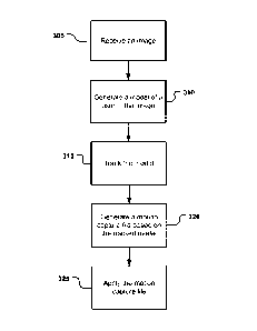
[0055] FIG. 5 depicts a flow diagram of an example method 300 for capturing
motions a user in a scene. The example method 300 may be implemented using,
for
example, the capture device 20 and/or the computing environment 12 of the
target
recognition, analysis, and tracking system 10 described with respect to FIGs.
1A-4. In an
example embodiment, the example method 300 may take the form of program code
(i.e.,
instructions) that may be executed by, for example, the capture device 20
and/or the
computing environment 12 of the target recognition, analysis, and tracking
system 10
described with respect to FIGs. 1A-4.
[0056] According to one embodiment, at 305, an image may be received. For
example, the target recognition, analysis, and tracking system may include a
capture
device such as the capture device 20 described above with respect to FIGs. 1A-
2. The
capture device may capture or observe a scene that may include one or more
targets. In an
example embodiment, the capture device may be a depth camera configured to
obtain an
image such as an RGB image, a depth image, or the like of the scene using any
suitable
technique such as time-of-flight analysis, structured light analysis, stereo
vision analysis,
or the like.
[0057] For example, in one embodiment, the image may include a depth image.
The depth image may be a plurality of observed pixels where each observed
pixel has an
observed depth value. For example, the depth image may include a two-
dimensional (2-
D) pixel area of the captured scene where each pixel in the 2-D pixel area may
represent a
depth value such as a length or distance in, for example, centimeters,
millimeters, or the
like of an object in the captured scene from the capture device.
[0058] FIG. 6 illustrates an example embodiment of a depth image 400 that may
be received at 305. According to an example embodiment, the depth image 400
may be an
image or frame of a scene captured by, for example, the 3-D camera 26 and/or
the RGB
camera 28 of the capture device 20 described above with respect to FIG. 2. As
shown in
FIG. 6, the depth image 400 may include a human target 402 corresponding to,
for
example, a user such as the user 18 described above with respect to FIGs. lA
and 1B and
one or more non-human targets 404 such as a wall, a table, a monitor, or the
like in the
captured scene. As described above, the depth image 400 may include a
plurality of
observed pixels where each observed pixel has an observed depth value
associated
- 14 -
CA 02757173 2011 09 29
WO 2010/126816 PCT/US2010/032366
therewith. For example, the depth image 400 may include a two-dimensional (2-
D) pixel
area of the captured scene where each pixel in the 2-D pixel area may
represent a depth
value such as a length or distance in, for example, centimeters, millimeters,
or the like of a
target or object in the captured scene from the capture device. In one
embodiment, the
depth image 400 may be colorized such that different colors of the pixels of
the depth
image correspond to and/or visually depict different distances of the human
target 402 and
non-human targets 404 from the capture device. For example, according to one
embodiment, the pixels associated with a target closest to the capture device
may be
colored with shades of red and/or orange in the depth image whereas the pixels
associated
with a target further away may be colored with shades of green and/or blue in
the depth
image.
[0059] Referring back to FIG. 5, in one embodiment, upon receiving the image,
at 305, the image may be downsampled to a lower processing resolution such
that the
depth image may be more easily used and/or more quickly processed with less
computing
overhead. Additionally, one or more high-variance and/or noisy depth values
may be
removed and/or smoothed from the depth image; portions of missing and/or
removed
depth information may be filled in and/or reconstructed; and/or any other
suitable
processing may be performed on the received depth information may such that
the depth
information may used to generate a model such as a skeletal model, which will
be
described in more detail below.
[0060] At 310, a model of a user in the image may be generated. For example,
upon receiving the image, the target recognition, analysis, and tracking
system may
determine whether the depth image includes a human target corresponding to,
for
example, a user such as the user 18, described above with respect to FIGs. 1A-
1B, by
flood filling each target or object in the depth image and comparing each
flood filled target
or object to a pattern associated with a body model of a human in various
positions or
poses. The flood filled target or object that matches the pattern may then be
isolated and
scanned to determine values including, for example, measurements of various
body parts.
According to an example embodiment, a model such as a skeletal model, a mesh
model, or
the like may then be generated based on the scan. For example, according to
one
embodiment, measurement values that may be determined by the scan may be
stored in
one or more data structures that may be used to define one or more joints in a
model. The
one or more joints may be used to define one or more bones that may correspond
to a body
part of a human.
- 15 -
CA 02757173 2011 09 29
WO 2010/126816 PCT/US2010/032366
[0061] FIG. 7 illustrates an example embodiment of a model 500 that may be
generated for a human target at, for example, 310. According to an example
embodiment,
the model 500 may include one or more data structures that may represent, for
example,
the human target 402 described above with respect to FIGs. 6 as a three-
dimensional
model. Each body part may be characterized as a mathematical vector defining
joints and
bones of the model 500.
[0062] As shown in FIG. 7, the model 500 may include one or more joints jl-
j18.
According to an example embodiment, each of the joints jl-j18 may enable one
or more
body parts defined therebetween to move relative to one or more other body
parts. For
example, a model representing a human target may include a plurality of rigid
and/or
deformable body parts that may be defined by one or more structural members
such as
"bones" with the joints jl-j18 located at the intersection of adjacent bones.
The joints jl-
18 may enable various body parts associated with the bones and joints jl-j18
to move
independently of each other. For example, the bone defined between the joints
j7 and j11,
shown in FIG. 7, may correspond to a forearm that may be moved independent of,
for
example, the bone defined between joints j15 and j17 that may correspond to a
calf
[0063] As described above, each of the body parts may be characterized as a
mathematical vector having an X value, a Y value, and a Z value defining the
joints and
bones shown in FIG. 7. In an example embodiment, intersection of the vectors
associated
with the bones, shown in FIG. 7, may define the respective point associated
with joints jl-
j 18.
[0064] Referring back to FIG. 5, at 315, the model may then be tracked such
that
the model may be adjusted based on movement by the user. According to one
embodiment, the model such as the model 500 described above with respect to
FIG. 7 may
be a representation of a user such as the user 18 described above with respect
to FIGs. lA
and 1B. The target recognition, analysis, and tracking system may observe or
capture
movements from the user such as the user 18 that may be used to adjust the
model.
[0065] For example, a capture device such as the capture device 20 described
above with respect to FIGs. 1A-2 may be observe or capture multiple images
such as
depth images, RGB images, or the like of a scene that may be used to adjust
the model.
According to one embodiment, each of the images may be observed or captured
based on
a defined frequency. For example, the capture device may observe or capture a
new image
of a scene every millisecond, microsecond, or the like.
- 16 -
CA 02757173 2011 09 29
WO 2010/126816 PCT/US2010/032366
[0066] Upon receiving each of the images, information associated with a
particular image may be compared to information associated with the model to
determine
whether a movement may have been performed by the user. For example, in one
embodiment, the model may be rasterized into a synthesized image such as a
synthesized
depth image. Pixels in the synthesized image may be compared to pixels
associated with
the human target in each of the received images to determine whether the human
target in
a received image has moved.
[0067] According to an example embodiment, one or more force vectors may be
computed based on the pixels compared between the synthesized image and a
received
image. The one or more force may then be applied or mapped to one or more
force-
receiving aspects such as joints of the model to adjust the model into a pose
that more
closely corresponds to the pose of the human target or user in physical space.
[0068] According to another embodiment, the model may be adjusted to fit
within a mask or representation of the human target in each of the received
images to
adjust the model based on movement of the user. For example, upon receiving
each of the
observed images, the vectors including the X, Y, and Z values that may define
each of the
bones and joints may be adjusted based on the mask of the human target in each
of the
received images. For example, the model may be moved in an X direction and/or
a Y
direction based on X and Y values associated with pixels of the mask of the
human in each
of the received images Additionally, joints and bones of the model may be
rotated in a Z
direction based on the depth values associated with pixels of the mask of the
human target
in each of the received images.
[0069] FIGs. 8A-8C illustrate an example embodiment of a model being adjusted
based on movements or gestures by a user such as the user 18 described above
with
respect to FIGs. lA and 1B. As shown in FIGs. 8A-8C, the model 500 described
above
with respect to FIG. 7 may be adjusted based on movements or gestures of the
user at
various points observed and captured in the depth images received at various
points in
time as described above. For example, as shown in FIG. 8A, the joints j4, j8,
and j12 and
the bones defined therebetween of the model 500 may be adjusted to represent
pose 502
when the user raises his or her left arm by applying one or more force vectors
or adjusting
the model to fit with a mask for a human target in images received at various
points in
time as described above. The joints j8 and j12 and the bone defined
therebetween may
further be adjusted to a pose 504 and 506, as shown in FIGs. 8B-8C, when the
user waves
by moving his or her left forearm. Thus, according to an example embodiment,
the
- 17 -
CA 02757173 2011 09 29
WO 2010/126816 PCT/US2010/032366
mathematical vector defining the joints j4, j8, and j12 and the bones
associated with the
forearm and bicep therebetween may include vectors with an X value, a Y value,
and a Z
value that may be adjusted to correspond to poses 502, 504, and 506 by
applying force
vectors or fitting the model within a mask as described above.
[0070] Referring back to FIG. 5, at 320, a motion capture file of the tracked
model may be generated. For example, the target recognition, analysis, and
tracking
system may render and store a motion capture file that may include one or more
motions
such as a waving motion, a swinging motion such as a golf swing, a punching
motion, a
walking motion, a running motion, or the like specific to the user such as the
user 18
described above with respect to FIGs. lA and 1B. According to one embodiment,
the
motion capture file may be generated in real-time based on the information
associated with
the tracked model. For example, in one embodiment, the motion capture file may
include,
for example, the vectors including the X, Y, and Z values that may define the
joints and
bones of the model as it is being tracked at various points in time.
[0071] In one example embodiment, a user may be prompted to perform various
motions that may be captured in the motion capture file. For example, an
interface may be
displayed that may prompt the user to, for example, walk or perform a golf
swing motion.
As described above, the model being tracked may then be adjusted based on
those motions
at various points in time and a motion capture file of the model for the
prompted motion
may be generated and stored.
[0072] In another embodiment, the motion capture file may capture the tracked
model during natural movement by the user interacting with the target
recognition,
analysis, and tracking system. For example, the motion capture file may be
generated
such that the motion capture file may naturally capture any movement or motion
by the
user during interaction with the target recognition, analysis, and tracking
system.
[0073] According to one embodiment, the motion capture file may include
frames corresponding to, for example, a snapshot of the motion of the user at
different
points in time. Upon capturing the tracked model, information associated with
the model
including any movements or adjustment applied thereto at a particular point in
time may
be rendered in a frame of the motion capture file. The information in the
frame may
include, for example, the vectors including the X, Y, and Z values that may
define the
joints and bones of the tracked model and a time stamp that may be indicative
of a point in
time in which, for example, the user performed the movement corresponding to
the pose
of the tracked model.
- 18 -
CA 02757173 2011 09 29
WO 2010/126816 PCT/US2010/032366
[0074] For example, as described above with respect to FIGs. 8A-8C, the model
500 may be tracked and adjusted to form poses 502, 504, and 506 that may be
indicative
of the user waving his or her left hand at particular points in time. The
information
associated with joints and bones of the model 500 for each of the poses 502,
504, and 506
may be captured in a motion capture file.
[0075] For example, pose 502 of the model 500, shown in FIG. 8A, may
correspond to a point in time when a user initially raises his or her left
arm. The pose 502
including information such as the X, Y, and Z values of the joints and bones
for the pose
502 may be rendered in, for example, a first frame of the motion capture file
having a first
time stamp associated with the point in time after the user raises his or her
left arm.
[0076] Similarly, poses 504 and 506 of the model 500, shown in FIGs. 8B and
8C, may correspond to a point in time when a user waves his or her left hand.
The poses
504 and 506 including information such as the X, Y, and Z values of the joints
and bones
for the poses 504 and 506 may be rendered in, for example, respective second
and third
frames of the motion capture file having respective second and third time
stamps
associated with different point in time of the user waving his or her left
hand.
[0077] According to an example embodiment, the first, second, and third frames
associated with the poses 502, 504, and 506 may be rendered in the motion
capture file in
a sequential time order at the respective first, second, and third time
stamps. For example,
the first frame rendered for the pose 502 may have a first time stamp of 0
seconds when
the user raises his or her left arm, the second frame rendered for the pose
504 may have a
second time stamp of 1 second after the user moves his or her left hand in an
outward
direction to begin a waving motion, and the third frame rendered for the pose
506 may
have a third time stamp of 2 seconds when the user moves his or her left hand
in an inward
direction to complete a waving motion.
[0078] At 325, the motion capture file may be applied to an avatar or game
character. For example, the target recognition, analysis, and tracking system
may apply
one or more motions of the tracked model captured in the motion capture file
to an avatar
or game character such that the avatar or game character may be animated to
mimic
motions performed by the user such as the user 18 described above with respect
to FIGs.
lA and 1B. In an example embodiment, the joints and bones in the model
captured in the
motion capture file may be mapped to particular portions of the game character
or avatar.
For example, the joint associated with the right elbow may be mapped to the
right elbow
of the avatar or game character. The right elbow may then be animated to mimic
the
- 19 -
CA 02757173 2011 09 29
WO 2010/126816
PCT/US2010/032366
motions of the right elbow associated with the model of the user in each frame
of the
motion capture file.
[0079] According to an example embodiment, the target recognition, analysis,
and tracking system may apply the one or more motions as the motions are
captured in the
motion capture file. Thus, when a frame is rendered in the motion capture
file, the
motions captured in the frame may be applied to the avatar or game character
such that the
avatar or game character may be animated to immediately mimic the motions
captured in
the frame.
[0080] In another embodiment, the target recognition, analysis, and tracking
system may apply the one or more motions after the motions may be captured in
a motion
capture file. For example, a motion such as a walking motion may be performed
by the
user and captured and stored in the motion capture file. The motion such as
the walking
motion may then be applied to the avatar or game character each time, for
example, the
user subsequently performs a gesture recognized as a control associated with
the motion
such as the walking motion of the user. For example, when a user lifts his or
her left leg, a
command that causes the avatar to walk may be initiated. The avatar may then
begin
walking and may be animated based on the walking motion associated with the
user and
stored in the motion capture file.
[0081] FIGs. 9A-9C illustrate an example embodiment of an avatar or game
character 600 that may be animated based on a motion capture file at, for
example, 325.
As shown in FIGs. 9A-9C, the avatar or game character 600 may be animated to
mimic a
waving motion captured for the tracked model 500 described above with respect
to FIGs.
8A-8C. For example, the joint j4, j8, and j12 and the bones defined
therebetween of the
model 500 shown in FIGs. 8A-8C may be mapped to a left shoulder joint j4', a
left elbow
joint j8', and a left wrist joint j12' and the corresponding bones of the
avatar or game
character 600 as shown in FIGs. 9A-9C. The avatar or game character 600 may
then be
may animated into poses 602, 604, and 606 that mimic the poses 502, 504, and
506 of the
model 500 shown in FIGs. 8A-8C at the respective first, second, and third time
stamps in
the motion capture file.
[0082] Thus, in an example embodiment, the visual appearance of an on-screen
character may be changed in response to the motion capture file. For example,
a game
player such as the user 18 described above with respect to FIGs. 1A-1B playing
an
electronic game on a gaming console may be tracked by the gaming console as
described
herein. As the game player swings an arm, the gaming console may track this
motion,
- 20 -
CA 02757173 2011 09 29
WO 2010/126816 PCT/US2010/032366
then in response to the tracked motion, adjust the model such as the skeletal
model, mesh
model, or the like associated with the user accordingly. As described above,
the tracked
model may further be captured in a motion capture file. The motion capture
file may then
be applied to the on-screen character such that the on-screen character may be
animated to
mimic the actual motion of the user swinging their arm. According to example
embodiments, the on-screen character may be animated to swing, for example, a
golf club,
a bat, or throw a punch in a game exactly like the user swings his or her arm.
[0083] It should be understood that the configurations and/or approaches
described herein are exemplary in nature, and that these specific embodiments
or examples
are not to be considered limiting. The specific routines or methods described
herein may
represent one or more of any number of processing strategies. As such, various
acts
illustrated may be performed in the sequence illustrated, in other sequences,
in parallel, or
the like. Likewise, the order of the above-described processes may be changed.
[0084] The subject matter of the present disclosure includes all novel and
nonobvious combinations and subcombinations of the various processes, systems
and
configurations, and other features, functions, acts, and/or properties
disclosed herein, as
well as any and all equivalents thereof
-21 -