Note: Descriptions are shown in the official language in which they were submitted.
CA 02757507 201110 03
1
Table for keeping foods located in dishes warm and table comprising one
or more induction modules
Technical area
s The invention relates to a table for keeping food warm that is in dishes,
said table
having a storage surface for the dishes and having a carrying surface, located
beneath the storage surface, for receiving at least one heat source. The
invention
furthermore relates to a table having at least one induction module arranged
within the table. "Table" is to be understood as table-like furnishings such
as
buffets, counters or the like; the term "keeping warm" is intended to comprise
the
cooking and/or the presenting of food in dishes. Burners that contain fuel
paste,
for example, can serve as energy sources.
Prior art
Facilities are already known in the catering industry that keep food warm by
means of water baths heated with fossil energy so that the food can be
presented and offered as part of a buffet, for example. Conventional electric
burner hot plates are known from the food preparation sector, are arranged,
for
example, in housings or in stovetops, and are suitable both for heating and
cooking owing to their high heat output. Another alternative for keeping food
warm at buffets is the so-called infrared emitter. Said infrared emitters
serve to
heat food from both below and above.
CA 02757507 201110 03
2
All equipment has the disadvantage, particularly with the handling of burners,
that the food must be kept warm in hot water baths since the burners must not
come into contact with the dishes on which the food is served. Handling in
this
set-up is very unwieldy and not very effective. There is often the risk that
the food
will get overheated. Should one wish to avoid this, one still runs the risk
that the
food will be only lukewarm.
Nevertheless, DE 101035331 Al discloses a piece of heat-retaining equipment
that is arranged in a fixed manner in a flat surface, such as in a table top.
It has a
1o storage surface and at least one electrically heated heat source arranged
on a
carrying surface beneath the storage surface, the storage surface and the
upper
surface of the table top substantially being positioned in a common plane.
Such a
piece of heat-retaining equipment is fixed in, that is to say constructed
integrally
with, a dining table top and can furthermore be arranged in multiple positions
depending on the respective seating arrangement of individuals at the table.
Disadvantages of the prior art
A considerable disadvantage of the prior art is that heat can be lost during
the
transfer of heat from the heat source to the corresponding dishes that are
holding
food. Moreover, the ambient temperature can be easily over-heated, resulting
in
considerable discomfort for the user in both buffet presentation as well as
during
eating.
CA 02757507 201110 03
3
Problem to be solved by the invention
The object of the invention is to provide a piece of furniture, particularly
for
keeping food warm, in which the abovementioned disadvantages are not present
and in which a dining table can be installed very easily so that the food can
be
displayed in a buffet-like manner while it is simultaneously kept warm.
Solution of the problem
With furniture serving as a table, the solution to the problem consists in the
storage surface for the dishes holding the food being supported by a
continuous
table top and the carrying surface for at least one heat source being
supported
by an intermediate shelf, either the table top being configured as fixed and
the
intermediate shelf opposite the table top preferably being adjustable in
height
with respect to said table top, or alternatively the intermediate shelf being
configured as fixed and the table top being removable.
Advantages of the invention
A substantial advantage of the invention consists in the fact that a piece of
furniture in the form of a table, as with the present invention, can be easily
installed and used in its configuration as equipment designed to keep things
warm. The table top can, advantageously, be configured so as to swing open
like
a lid or it can be removable or alternatively translationally or rotationally
shiftable,
thereby providing easy access to the carrying surface.
CA 02757507 201110 03
4
Furthermore, it can be a great advantage if a plurality of heat sources are
provided on the carrying surface of the intermediate shelf in order to
increase the
number of warming locations, it being advantageous to position modularly
configured hot plates or induction modules on the intermediate shelf in the
piece
of furniture in such a manner that they are invisible to the observer or to
those
who, for example, are serving themselves at the buffet or eating at a table.
In this
way, keeping food warm can occur in a more purposeful manner. The heat
sources are preferably simply positioned on the carrying surface.
1o In theory, the table according to the invention has beneath the one table
surface
a second level. This second level in the form of the intermediate shelf can be
characterized in that it can be somewhat lowered for loading of the individual
induction modules and the second level (level on which the induction modules
are positioned) is larger, which substantially simplifies the handling of the
induction modules. Should the second level be loaded, this second level in the
form of an intermediate shelf can be raised in the direction of the first
level,
however with a certain distance being maintained between the surface of one
induction module and the bottom surface of the actual table surface.
Maintaining
this distance ensures that a certain stray field is present, making it
possible for
the food to be more effectively kept warm. It has also been shown that even a
defined distance from the induction module to the dish results in optimal
utilization and coupling of the energy.
CA 02757507 201110 03
It is allowed for by the alternatively provided embodiment, according to which
the
second level in the form of an intermediate shelf is configured as fixed
beneath
the first level (of the actual table level), that the table top can be removed
in order
to have greater ease of access to the respective heat sources. The table top
can
5 be configured for this purpose as being able to be swung open, that is to
say like
a lid, so that the individual induction modules can be placed from above onto
the
second level. Additional variants can consist in the table top being
configured as
simply removable or alternatively as translationally or rotationally shiftable
in one
manner or another.
With the design that is shown, a table is nevertheless provided in which the
individual induction modules can easily be placed on the intermediate shelf,
that
is to say the induction modules which are customarily difficult to access can
be
loaded and removed with greater ease.
The table top is preferably composed of calendered glass. This material has
the
added advantage that it is easy to clean and is furthermore advantageous
because the magnetic fields of the induction elements can easily penetrate
glass
materials in order to interact with the correspondingly designed dishes in
such a
manner that the food contained in the dishes can be heated up well or kept
warm.
CA 02757507 201110 03
6
It is moreover advantageous if the induction modules are configured in such a
manner that the respective induction coils are very clearly displayed on the
surface of the induction module, that is to say they can be recognized
optically,
so that this displayed indication is also visible through the calendered
glass. This
makes it possible for users who prepare the buffet or place dishes on the
table to
determine the correct positioning of the dishes.
The induction modules themselves are preferably configured as having a box
shape and contain, in addition to the necessary electronics, also the
requisite
1o induction coils. Each induction module has at least one induction coil, the
size of
the induction coil and thus of the "hot plate" being shown on the surface of
each
respective module. The induction modules themselves are powered electrically
and can be operated at different power levels. The induction modules
furthermore preferably have plug and socket connections, for example with
cables, plugs, and sockets for their power supply. One on-site wall socket is
sufficient for supplying power to a plurality of induction modules. The output
of
the induction module is also preferably individually adjustable for each
induction
module when power is supplied in a shared fashion.
The table according to the invention preferably has identical induction
modules.
Thus induction modules that differ in dimension, shape, output, etc are
unnecessary. Since the induction modules are positioned on the carrying
surface
of the table beneath the table top, their quantity and arrangement can vary
and
CA 02757507 201110 03
7
be adjusted specifically to the events in question. For large and/or long
dishes,
two or more induction modules can be positioned on the carrying surface. The
invention makes possible the problem-free adjustment of the induction modules
and their output to the dimensions, shape, and arrangement of the plates that
are
on the table top and are to be kept warm.
A display element can be provided on the surface of the induction modules in
order to represent the different power levels, by means of which display
element
the observer can verify the respective power level that has been set. In order
to
1o be able change the power levels, a remote control can be provided for the
induction modules in addition to the manually operable adjusting element that
may be provided. A remote control is advantageous in that the individual
induction modules can be operated separately since they are arranged beneath
the first level, that is to say the table top, and are thus difficult to
access. The
remote control can preferably be designed as an indicating instrument. What is
meant by this is that the remote control, in particular its housing, is
configured in
such a manner that user can recognize, preferably intuitively perceive, the
direction in which the remote control sends a signal. This is possible through
a
long-range remote control, for example. This has the added advantage that the
user can point to a certain induction module and set one of the pre-determined
power levels either by pressing a button or by turning a corresponding dial.
Owing to the optical configuration of the display instrument of the induction
modules, the user can recognize the respective power levels through the glass
CA 02757507 201110 03
8
table level as well. The display instrument can have light-emitting diodes,
for
example, to display the power levels. It is not necessary for the user to use
an
individual remote control for each individual induction module or for the user
to
change a channel. It is thereby possible to operate each induction module
s individually with one and the same remote control. It is sufficient merely
to point
such a remote control device in the direction of the desired induction module
so
that the transmitted signal reaches only the selected induction module.
The remote control preferably transmits a directed signal, the signal
dispersing,
1o diffusing, for example, in a conically-shaped fashion. If the remote
control is
within reasonably close proximity to the induction module, this will reliably
ensure
that the module is "hit". That is to say, the signal of the remote control
reaches
the receiver section of an induction module and does not reach the receiver
section of a neighboring induction module. The display element lets the user
15 know that an induction module has been adjusted or re-adjusted and which
induction module has been affected. The remote control can exhibit a short
range
of approximately 10 cm or several centimeters beyond 10 cm into the meter
range of about 1 m to 1.5 m or 2 m. The directive efficiency of the remote
control
is thereby sufficient to adjust precisely a desired induction module. The
remote
20 control preferably transmits an infrared signal that need not be a laser
beam
since a beam of light is sufficient that is optically focused with lenses
and/or
mirrors or alternatively that fans out in a conical shape. Visible light can
also be
used and has the advantage that the induction module that is
CA 02757507 201110 03
9
"hit" can be seen. A beam of light can also be used exclusively for aiming at
the
desired induction module and the signal can be transmitted from the remote
control to the induction module in a different manner. Moreover, it is
possible for
the remote control to use other signals such as, for example, acoustic,
ultrasonic,
or electromagnetic signals to adjust the power levels of the induction
modules.
In addition to the aforementioned adjusting of a power level, it is also
possible to
turn the respective induction modules on and off from the external side (from
the
respective side) of the table.
The induction modules are advantageously measured in their dimensions so that
they can be received by the dish furnishings and equipment known and used in
the food industry. Long dishes and food containers or platters in particular
can be
kept warm in such a manner that they overlap at least two induction modules.
All
induction modules can be configured as having the same dimensions.
A piece of furniture in the form of a table is thus created with which food
can be
very easily presented and kept warm, while it is also suitable for cooking
food
with the user neither being disturbed by a high environmental temperature nor
having to attend to the cooking module in question, in this instance induction
modules, as is customary with burners, for example.
CA 02757507 201110 03
The installation of the induction modules is very simple since they can be
inserted into a second level-the intermediate shelf-arranged beneath the
actual table top, and said induction modules can furthermore be arranged at a
certain distance to the upper surface of the table. It is accordingly not
necessary
5 to provide appropriate recesses in the table into which the induction
modules
must be placed without being afforded any flexibility in terms of arrangement.
In
contrast, it is possible to arrange the induction modules freely on the second
level. Loading the induction modules onto the second level is very easy since
different fittings are provided that make it possible to position induction
modules
10 easily on these levels. Operating the induction modules can likewise be
effected
in a simple and intuitive manner since the desired power level of an induction
module can be established by merely pointing the possible remote control
apparatus at the induction module to be set.
In this manner, the distance between induction module and dish can always be
maintained in an optimal operation range.
Additional advantages of the invention can be found in the following
description,
in the drawings, and in the claims.
Drawings
Fig. 1 shows a perspective view of a table according to the invention;
CA 02757507 201110 03
11
fig. 2 shows a perspective view of a table according to figure 1 on a
smaller scale, however at a time when induction modules are just
being inserted into the table;
fig. 3 shows a view of the table according to figure 2 with a plurality of
induction modules and
fig. 4 shows a perspective view of the table according to figure 3, while it
is being used as a buffet.
Description of an embodiment of the invention
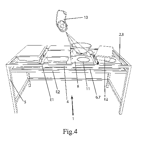
The table, referenced with numeral 1, represented in perspective in figure 1,
has
a storage surface 2 of a table top 3 composed of calendered glass, which
storage surface is positioned in a table frame 4. The table frame 4 is
supported
by four table legs 5 between which a carrying surface 6 in the form of an
intermediate shelf 7 is provided beneath the table top 3.
As is shown in figure 2, induction modules 8 serving as heat sources are
inserted
here corresponding to the arrows 9 between the table top 3 as the first level
El
of the table 1 and the intermediate shelf 7 as the second level E2. The second
level E2 is configured as height adjustable with respect to the first level
El, which
is indicated by arrow 10 in figure 1 and figure 2, that is to say the
clearance
between the first level El and the second level E2 can be increased. It is
thereby
CA 02757507 201110 03
12
possible to easily place the induction modules 8 on the carrying surface 8 of
level
E2. After placing all induction modules 8 according to figure 3, the
intermediate
shelf 7 of level E2, as represented by arrow 10, is pushed upward until a
smaller
distance is achieved between the underside of the table top 3 of the level El
and
the surface of the induction modules 8. In order to achieve optimal heating,
this
distance ought to be maintained.
The respective surfaces of the induction modules 8 are represented with a
circle
11 that corresponds to the diameter of the coil that is arranged in the
induction
1o module 8. The circles 11 are visible through the table top 3 that is
composed of
glass, preferably designed as frosted, so that dishes 12 in the form of bowls
and
crocks according to figure 4 can be easily positioned.
All induction modules 8 of the table are identical. For power supply purposes,
a
plurality of induction modules 8 are connected to one another by means of
cable
plug connections that are not shown. Two on-site wall outlets, for example,
are
sufficient for supplying power to the induction modules 8 of the table 1.
Despite
sharing a joint power supply, the power levels of the induction modules 8 can
be
adjusted independently of one another. The induction modules 8 optically
display
the set power levels by means of light emitting diodes, for example.
The table 1 has a remote control 13, which is shown as disproportionately
large
in figure 4, for adjusting the power levels of the induction modules 8. The
remote
CA 02757507 201110 03
13
control 13 transmits a cone-shaped optical signal in the infrared range, as is
indicated in figure 4 through dotted lines. A housing of the remote control 13
is
configured in such a manner that a user intuitively perceives the direction of
the
signal and can direct the remote control 13 so that its signal hits one
induction
module 8 the power level of which is to be adjusted or re-adjusted, without
the
signal affecting another neighboring induction module 8. It is possible to
adjust
the power levels of all induction modules 8 with one single remote control
apparatus 13 without the remote control 13 having to have different channels
or
another type of individualization of the induction modules 8. The user can
to recognize which induction module 8 is being adjusted or re-adjusted on the
display elements of the induction modules 8 so that the desired induction
module
8 can be adjusted or re-adjusted without effecting the same change in an
induction module 8 that is adjacent thereto, for example.
CA 02757507 201110 03
14
Reference numeral list
1 Table
2 Storage surface
3 Table top
4 Table frame
5 Table leg
6 Carrying surface
7 Intermediate shelf
8 Induction module
9 Arrow (installation)
10 Arrow (height adjustable)
11 Circle
12 Dishes
13 Remote control