Note: Descriptions are shown in the official language in which they were submitted.
CA 02758407 2011-11-15
OIL RECOVERY PROCESS
FIELD OF THE INVENTION
[0001] The present invention relates to oil recovery processes and more
particularly to oil
recovery processes that treat produced water and utilize a steam generator to
produce steam
from the treated produced water and inject the steam into an injection well.
BACKGROUND
[0002] Steam assisted gravity discharge (SAGD) refers to a widely used process
where
high pressure steam is injected into an injection well to melt bitumen or to
generally reduce the
viscosity of heavy oil to facilitate its removal. The bitumen or heavy oil and
condensed steam
flows by gravity to drain pipes buried below the oil deposit and the bitumen
or oil is pumped out
as an oil-water mixture. Once the oil-water mixture is pumped to the surface,
a number of
processes are utilized to treat the oil-water. First, oil is separated from
the oil-water mixture to
yield an oil product and produce water. The produced water is then treated to
remove total
dissolved solids and suspended solids. Various types of treatments can be
employed such as
filters for removing suspended solids and warm lime softeners or evaporators
to remove
dissolved solids. Cyclic Steam Simulation (CSS) process also works in the same
principle as
SAGD process with intermittent steam injection followed by oil-water mixture
extraction.
[0003] There are several types of steam generators that can be utilized to
generate steam
for use in a SAGD process for example. One type of steam generator is referred
to as the once
through steam generator. Once through steam generators have a number of
disadvantages or
drawbacks. They tend to have high blowdown and hence this gives rise to
thermal inefficiencies
and water wastage. Once through steam generators typically utilize inline
steam separators
and this results in additional blow down and additional heat recovery
equipment. Many once
through steam generators are designed with refractory/insulated furnaces.
These typically
1
CA 02758407 2011-11-15
require substantial maintenance. In addition, once through steam generators
have uncooled
supports for supporting steam generation coils. This also leads to high
maintenance. With
once through steam generators the turn down is limited and they typically have
very complex
flow circuits to manage. Moreover, the steam capacity is limited to about
300,000 LB/HR.
Typically once through steam generators require a relatively large footprint
and the capital cost
is high. When once through steam generators are used in heavy oil recovery
processes such
as commercial bitumen production, the resulting designs require numerous one
through steam
generation units and this results in high capital and operating costs.
[0004] A second type of steam generator is what is referred to as a drum
boiler. Drum
boilers have limited operating experience in heavy oil recovery processes and
in particular, have
not been widely used with feed water from an evaporator. Further, there is not
a great deal of
experience with drum boilers in handling upsets in water quality, a real
concern for oil
producers. Furthermore, with drum boilers it is expensive and time consuming
to clean the
tubes of the drum boiler. Finally, mechanical tube failures that result from
water quality issues
are expensive to repair.
[0005] Therefore, there is and continues to be a need for a steam generator
design for use
in heavy oil recovery processes that overcomes the shortcomings and
disadvantages of once
through steam generators and drum boilers.
SUMMARY
[0006] The present invention relates to a method of recovering oil and
producing steam for
injection into an injection well to assist in the recovery of oil. The method
includes recovering an
oil-water mixture from an oil bearing formation. The oil-water mixture is
separated into an oil
product and produced water which includes suspended solids-and dissolved
solids. The
produced water is directed to a treatment system that removes suspended solids
and dissolved
solids from the produced water. This yields treated water. The treated water
is then directed to
2
CA 02758407 2011-11-15
a forced circulation steam generator that includes a furnace having a burner
and at least one
water cooled wall and an evaporator unit. The treated water is pumped through
the water
cooled wall and the evaporator unit. The water being pumped through the water
cooled wall
and the evaporator unit is heated and yields a water-steam mixture that
comprises
approximately 10% to 30% quality steam. The water-steam mixture is then
directed to a steam
drum that separates the steam from the water-steam mixture to form injection
steam that
comprises 95% or more quality steam. The injection steam is then injected into
an injection well
to facilitate recovery of the oil-water mixture from the oil bearing
formation.
[0007] Other objects and advantages of the present invention will become
apparent and
obvious from a study of the following description and the accompanying
drawings which are
merely illustrative of such invention.
BRIEF DESCRIPTION OF THE DRAWINGS
[0008] Figure 1 is a schematic illustration of the oil recovery process of the
present
invention.
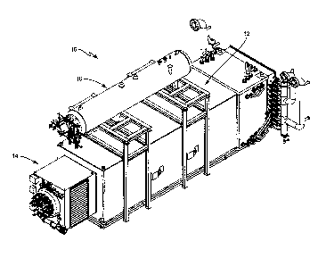
[0009] Figure 2 is a perspective view of the forced circulation steam
generator of the
present invention.
[0010] Figure 3 is a cross-sectional view of the furnace of the steam
generator as shown in
Figure 2.
[0011] Figure 4A is a perspective view of a tube element that forms a part of
a heat
exchanger module.
[0012] Figure 4B is a perspective view of the heat exchanger module comprised
of a series
of tube elements.
[0013] Figure 5A is a perspective view of a tube element that makes up an
evaporator unit.
[0014] Figure 5B is a perspective view of the evaporator unit.
3
CA 02758407 2011-11-15
[0015] Figure 6 is a fragmentary perspective view showing a water cooled wall
assembly of
the furnace that forms a part of the steam generator.
[0016] Figure 7 is a perspective cut-away view illustrating portions of the
furnace of the
steam generator as well as the water cooled walls and evaporator unit in the
furnace.
[0017] Figure 8 is a graphical illustration showing the relationship between
tube metal
temperature and quality steam and particularly comparing tube metal
temperature and quality
steam of the forced circulation steam generator of the present invention with
a conventional
once through steam generator.
[0018] Figure 9 is a schematic illustration showing the basic operation of the
forced
circulation steam generator of the present invention.
DETAILED DESCRIPTION
[0019] With reference to the drawings, particularly Figure 1, there is shown
therein an oil
recovery process that employs a forced circulation steam generator 10. As will
be appreciated
from subsequent portions of the disclosure, the forced circulation steam
generator 10 functions
to produce steam that is injected into an injection well 200 that is typically
spaced from an oil
well or oil bearing formation. More particularly, in one embodiment, the
present invention is a
heavy oil recovery process that employs steam assisted gravity discharge,
commonly referred
to as a SAGD process.
[0020] Viewing Figure 1 in more detail, the forced circulation steam generator
10 produces
steam that is directed into the injection well 200. Once in the injection well
200, the steam
functions to fluidize heavy oil, sometimes referred to as bitumen, in the oil
bearing formation
which is typically horizontally separated from the injection well 200. The
process of the present
invention can be utilized in a wide range of heavy oil recovery processes
where it is desired to
utilize steam to facilitate the removal of heavy oil from an oil bearing
formation. For example,
4
CA 02758407 2011-11-15
one area in the world that is particularly suited for the process disclosed
herein is the tar sands
region in Alberta, Canada for example.
[0021] Steam entering the injection well 200 eventually condenses and an oil-
water mixture
204 results and this oil-water mixture moves through the oil bearing formation
202. Eventually
the oil-water mixture 204 is consolidated in an oil-water gathering well and
the oil-water mixture
204 is pumped to the surface.
[0022] Once the oil-water mixture 204 reaches the surface, it is directed to
an oil-water
separator 206. Oil separator 206 separates oil from the mixture and produces
an oil product
208. The remaining water is referred to as produced water 209. The produced
water 209, after
separation from the oil, is further de-oiled by a de-oiling process 210. De-
oiling process 210
may be accomplished in various ways such as by utilizing a dissolved air
flotation system with
the assistance of the addition of a de-oiling polymer.
[0023] After the de-oiling process 210 and prior to the produced water
reaching the forced
circulation steam generator 10 it is necessary to treat the produced water to
remove
contaminants such as suspended solids and total dissolves solids (TDS)
including contaminants
such as hardness and silica. At various points downstream from the de-oiling
process 210,
various types of filtration devices, such as nutshell filters, multi-media
filters, membranes, etc.
can be employed to remove suspended solids or particulates from the produced
water. These
processes are generally included in the section of the process denoted
treatment system 212 in
Figure 1. There are various processes that may be utilized in the treatment
section 212 to deal
with hardness, silica, organics and other dissolved solids. For example, warm
lime softeners in
combination with downstream filtration devices and ion exchange units can be
utilized to
remove hardness and silica as well as other dissolved solids. In the
alternative, evaporators
can be utilized to remove hardness, silica and other dissolved solids and
again further
downstream polishing processes can be utilized to purify a distillate produced
by the evaporator.
In the end, it is the aim of the process of the present invention to remove
sufficient contaminants
CA 02758407 2011-11-15
from the produced water before entering the forced circulation steam generator
so as to prevent
scaling and fouling of metal surfaces found in the steam generator and any
associated
equipment.
[0024] Various softening chemicals such as lime, flocculating polymer and soda
ash may be
used in a warm lime softening process. Typically the warm lime softener
produces waste
sludge which can be further treated and disposed. As noted above, polishing
downstream from
the warm lime softener can include an ion exchange process which typically
includes hardness
removal by a weak acid cation ion exchange system that can be utilized to
remove hardness
and in some cases at least some alkalinity.
[0025] Various types of evaporators can be utilized to treat the produced
water prior to
reaching the steam generator 10. For example, the produced water 209 can be
treated and
conditioned in a mechanical vapor recompression evaporator. Such an evaporator
will
concentrate the incoming produced water. Pretreatment prior to reaching the
evaporator can be
employed when necessary. For example sulfuric acid or hydrochloric acid can be
used to lower
the pH of the produced water prior to reaching the evaporator so that bound
carbonates are
converted to free gaseous carbon dioxide which can be removed along with other
dissolved
gases by an upstream deaerator. After pretreatment, if necessary, the produced
water is
directed to the evaporator which produces a concentrated brine and steam which
condenses to
form a distillate. Generally the concentrated brine in the evaporator is
recirculated and a small
portion of the recirculating concentrated brine is removed. In the evaporator,
the dissolved
solids in the produced water are concentrated since water is being removed
from the produced
water.
[0026] In some cases, the distillate produced by the evaporator may require
further treating
to remove organics and other residual dissolved solids. In some cases it may
be necessary to
remove ions from the distillate produced by the evaporator. In many cases the
residual
dissolved solids in the distillate include salts other than hardness. In one
process, the removal
6
CA 02758407 2011-11-15
of dissolved solids downstream from the evaporator can be accomplished by
passing the
distillate, after being subjected to a heat exchanger, through an ion exchange
system. Such ion
exchange systems may be of the mix bed type and aimed at removing selected
solids. In other
designs, the removal of residual dissolved solids can be accomplished by
passing the distillate
through a heat exchanger and then through an electrodeionization (EDI) system.
The reject or
waste stream from all of these polishing processes can be recycled upstream of
the evaporator
for further treatment by the evaporator. As noted above, various treatment
systems 212 can be
utilized upstream of the steam generator to remove various contaminants from
the produced
water stream. It is contemplated that utilizing evaporators to remove total
dissolved solids from
the produced water stream may be preferable. But it is understood and
appreciated that other
pretreatment processes may be employed to treat the produced water prior to
its introduction
into the downstream generator.
[0027] Downstream of the treatment system 212 is the forced circulation steam
generator
10. Details of the forced circulation steam generator 10 will be discussed
later but it is beneficial
to briefly review the forced circulation steam generator and discuss how it
receives the treated
produced water from the treatment system 212 and produces steam for injection
into the
injection well 200. Generally the effluent from the treatment system 212 is
directed to a steam
drum 16 that forms part of the forced circulation steam generator 10. Water
from the steam
drum 16 is pumped by one or more pumps through what can generally be described
as two heat
exchanger systems or circuits incorporated into the furnace of the steam
generator 10. First
there is an evaporator unit contained in the furnace. In addition there is
provided water cooled
walls that form a part of the furnace unit. The one or more pumps pump water
from the steam
drum 16 through both the evaporator unit and the water cooled walls. In each
case a water-
steam mixture is produced and returned to the steam drum 16. The forced
circulation steam
generator 10 includes flow controls for independently controlling the flow of
water through the
evaporator unit and the water cooled walls such that approximately 10% to
approximately 30%
7
CA 02758407 2011-11-15
quality steam is produced in each circuit. Steam drum 16 separates steam from
the water in the
steam drum 16 and produces a steam that exceeds 95% quality steam and in a
preferred
embodiment produces 99% or higher quality steam. Steam produced by the steam
drum 16 is
directed into the injection well 200. Steam drum 16 also produces a blow down
stream that is
on the order of 1 to 2% compared to the feed to the steam drum.
[0028] Turning to Figures 2-9, the forced circulation steam generator 10 is
shown therein in
more detail. The forced circulation steam generator 10 comprises three basic
components: a
furnace indicated generally by the numeral 12, a burner indicated generally by
the numeral 14,
and a steam drum indicated generally by the numeral 16. As discussed above,
water from the
steam drum 16 is forced and circulated through water cooled walls forming a
part of the furnace
12 and through an evaporator unit indicated generally by the numeral 40.
Burner 14 supplies
heat to the furnace 12 that heats the water passing through the water cooled
walls and the
evaporator unit 40 resulting in a water-steam mixture being produced in the
water cooled walls
and the evaporator unit. The water-steam mixtures are directed to the steam
drum 16 where
the steam is separated from the water. One of the features of the forced
circulation steam
generator 10 of the present invention is that the heat supplied by the burner
14 and the flow of
water through the water cooled walls and the evaporator 40 are controlled so
as to limit the
quality of steam produced in the water cooled walls and the evaporator unit.
As discussed
below, controls are instituted such that the water cooled walls and the
evaporator unit 40
produce steam that is 30% or less quality steam. Furthermore, the amount of
water pumped
and circulated through the water cooled walls and the evaporator unit 40 is
substantially greater
than the amount of steam produced by the water cooled walls and the evaporator
unit 40. In
one design illustrated herein, the amount of water pumped from the steam drum
16 to and
through the water cooled walls and evaporator unit 40 is greater than five
times the amount of
steam produced in the water cooled walls and the evaporator unit 40. In a
steam generator
circulation circuit context, the flow of water and steam is expressed Ibs\hr
unit or as a ratio of
8
CA 02758407 2011-11-15
water to steam flow in the circuits. In this particular case the flow of water
into the two circuits is
at least a 5:1 circulation ratio. That is, the flow of water from the steam
drum 16 into the two
circuits is at least 5 parts water to 1 part of steam produced in the
circuits. That is, 5 parts of
water directed into the two circuits exits the two circuits as 4 parts water
and 1 part steam. This
enables a relatively high wetted area in both water cooled walls and
evaporator circuits and
resultant lower tube wall temperatures. The quality steam produced at the
steam drum exceeds
95% and in a preferred design is 99% greater.
[0029] Forced circulation steam generator 10 comprises a furnace indicated
generally by
the number 12. See Figure 7. Furnace 12 comprises water cooled walls. In the
embodiment
contemplated herein, the sides, bottom and top of the furnace12 includes water
cooled walls.
[0030] The water cooled walls are shown in Figures 4A, 4B, 6 and 7. The water
cooled
walls form a part of a wall assembly that is particularly illustrated in
Figure 6. Essentially each
water cooled wall includes a heat exchanger module indicated generally by the
numeral 18.
See Figure 4B. Each heat exchanger module 18 includes a series of parallel
tubes or pipes
through which water flows. In the embodiment illustrated herein, each side as
well as the top
and bottom of the furnace 12 will include a heat exchanger module 18. That is,
for example,
one module 18 (shown in Figure 4B) would extend along one side of the furnace
12. Likewise,
one module 18 would extend along the top of the furnace and another module 18
would extend
along the bottom of the furnace. In the end, all of the exterior walls of the
furnace 12 would
include a module that would enable the exterior walls to be water cooled. Each
module 18
includes a series of tube elements with each tube element being indicated
generally by the
numeral 20 and shown in Figure 4A. In the case of the module 18 shown in
Figure 4B, the
same includes multiple tube elements 20 that are stacked or nested together.
Each tube
element 20, shown in Figure 4A, includes a water inlet 20A, an outlet 20B, and
a series of
parallel tube segments 20C. Each tube element 20 is designed such that a
series of the tube
9
CA 02758407 2011-11-15
elements can be integrated to form the module 18 in such a fashion that the
tube segments 20C
lie in generally the same plane.
[0031] Module 18 includes a plurality of webs or fins 22. These are elongated
pieces of
metal that are welded between the respective tube segments 20C. The tube
segments or
sections 20C along with the fins 22 form a generally impervious wall.
[0032] Continuing to refer to Figure 4B and the module 18, it is seen that the
module
includes a surrounding frame structure that imparts rigidity to the module and
at the same time
functions as a manifold for directing inlet water into the various tube
elements 20 and for
directing a water-steam mixture from the various tube elements. In the
particular embodiments
shown herein, the manifold structure being referred to includes an inlet
manifold 24 and an
outlet manifold 26. Inlet manifold 24 for each module 18 is connected directly
or at least
indirectly to a source of water and to the inlet 20A. Outlet manifold 26 is
connected to the outlet
20B of each module 18 and is also directly or indirectly connected to a fluid
connection between
the furnace and the steam drum 16.
[0033] Module 18 comprises a part of an exterior wall that is partially shown
in Figure 6.
Module 18 is disposed along the inside of the wall assembly. Disposed outside
of the wall
assembly is an outer skin 30. Disposed between the module 18 and the skin 30
is an insulation
layer 32. In one embodiment of the present invention, the wall assembly shown
in Figure 6
forms the side walls, top and bottom of the furnace 12.
[0034] As viewed in Figure 7, the left end of the furnace 12 includes an
opening 34 that
permits the flame to be projected from the burner 14 into the furnace 12.
Continuing to refer to
Figure 7, the right end of the furnace 12 also includes an opening indicated
generally by the
numeral 36 for permitting exhaust gases to be exhausted form the steam
generator 10.
[0035] Returning to the evaporator unit 40, as shown in Figure 5B, the
evaporator unit
includes a series of stacked tube elements indicated generally by the numeral
42. Figure 5A
CA 02758407 2011-11-15
shows one tube element 42. Each tube element 42 includes an inlet 42A and an
outlet 42B. In
addition, each tube element 42 includes a series of parallel tube segments or
sections 42C.
Evaporator unit 40 is formed by stacking a series of the tube elements 42 one
over the other.
Like the modules 18, the evaporator unit 40 is communicatively connected to at
least two
manifolds that facilitate the flow of water into the evaporator unit 40 and
which receive the
water-steam mixture produced by the evaporator unit. As seen in Figure 7,
there is provided an
inlet manifold 44 that is operatively connected to the inlets 42A of the tube
elements 42.
Further, there is provided an outlet manifold 46 that is operatively connected
to the outlets 42B
of the tube elements 42. Thus, it is appreciated that water entering the
evaporator unit 40
passes into and through the inlet manifold 44 while the water-steam mixture
produced by the
evaporator unit is directed out the outlet manifold 46. As seen in Figure 7,
the evaporator unit
40 is disposed in an end portion of the furnace 12 opposite the burner 14.
[0036] As seen in Figure 1, the forced circulation steam generator 10 includes
a steam
drum indicated generally by the numeral 16. As is appreciated, the steam drum
16 functions to
receive water-steam mixtures from the wall modules 18 and the evaporator unit
40. Once the
steam mixtures have been received in the steam drum 16, the steam drum
functions to separate
the steam from the water. The system and process disclosed herein is designed
to result in the
steam drum 16 producing a very high quality steam, a quality steam of at least
95% and in a
preferred system and process a quality steam of 99% or more.
[0037] Figure 9 is a schematic illustration showing the steam drum 16. The
steam drum
includes inlets 60A and 60B with inlet 60A being operative to receive the
water-steam mixture
from the wall modules 18 while inlet 60B is operative to receive the water-
steam mixture from
the evaporator unit 40. Further, the steam drum 16 includes various ports for
enabling access
for sensors and other instruments.
[0038] The forced circulation steam generator 10 is powered with a
conventional gas burner
14. Details of the burner 14 are not dealt with herein because such is not per
se material to the
11
CA 02758407 2011-11-15
present invention and further, burners of the type employed in the forced
circulation steam
generator 10 are well known and conventional. One exemplary burner 14 that is
suitable for the
forced circulation steam generator 10 is the "NATCOM" Ultra Low NOx burner
supplied by
Cleaver-Brooks of Lincoln, Nebraska. Briefly, however, the burner 14 is at
least partially housed
in a housing 14A. See Figures 2 and 7. Burner 14 is mounted in the housing 14A
at the left
end of the furnace 12 as viewed in Figure 7. In this position the burner 14
shoots a substantial
flame into the left end of the furnace 12 and in the process is effective to
heat water passing
through the water cooled walls as well as the evaporator unit 40.
[0039] Turning to Figure 9, shown therein is a schematic illustration showing
basic
components of the forced circulation steam generator 10 and how steam is
produced and
injected into the injection weld 200. As shown in Figure 9, the forced
circulation steam
generator includes a pair of pumps 80 and 82. Pumps 80 and 82 can be of
various types but in
one embodiment they are centrifugal pumps and their output or flow is
generally a function of
pressure. Pumps 80 and 82 are connected to an outlet of the steam drum 16 via
line 100.
Furthermore, the pumps 80 and 82 are operatively interconnected between the
evaporator unit
40 and the water cooled wall modules 18 and the steam drum 16. Pumps 80 and 82
function to
pump water from the steam drum 16 through the evaporator unit 40 and the water
cooled wall
modules 18.
[0040] As shown in Figure 9, the output of the pumps 80 and 82 are coupled by
line 83.
Extending from line 83 are two lines 104 and 106 with line 104 functioning to
feed the
evaporator unit 40 and line 106 functioning to feed the water cooled wall
modules 18. Disposed
between the pumps and the evaporator unit 40 and the water cooled wall modules
18 is a flow
control system which functions to vary the flow of water through the
evaporator unit 40 and
water cooled wall modules 18. The control mechanism utilized is a pair of flow
sensors 88 and
90. Flow sensors 88 and 90 are each operatively connected to a controller 92.
In the
embodiment illustrated herein, two controllers are shown but it is appreciated
that a single
12
CA 02758407 2011-11-15
controller with the ability to produce a series of independent control signals
could be utilized. In
any event, each controller 92 is operatively connected with a flow control
value 84 and 86. As
noted above, the function of the controller 92 is to control the flow of water
through the
evaporator unit 40 and the water cooled wall modules 18. Controller 92 is
programmed to
exercise control based on one or more parameters or variables. The system and
process is
designed to produce approximately 10% to approximately 30% quality steam in
each of the
circuits, i.e., evaporator unit and the water cooled wall modules 18. It is
known that there is a
relationship between the burner firing rate and flow. That is, to achieve a
certain quality steam,
the firing rate and flow are directly proportional. That is, as the firing
rate is increased, the flow
should also increase. Further, as the firing rate is decreased, the flow
should be decreased in
order to produce the same quality steam. Therefore, the controller 92 is
programmed to control
the flow control valves 84 and 86 in response to the firing rate of the burner
14. Generally
speaking, as the firing rate is increased, the flow control valves 84 and 86
are actuated so as to
increase flow from the pumps 80 and 82 through the evaporator unit 40 and the
water cooled
wall modules 18. Likewise, as the firing rate of the burner 14 is decreased,
the controllers 92
generally control the flow control valves 84 and 86 so as to generally
decrease the flow of water
through the evaporator unit 40 and the water cooled wall modules 18. As noted
above, the
controllers 92 can be programmed in various ways to achieve the desired
quality steam
produced. For example, in addition to firing rate, the controllers 92 could
also be programmed
to consider the water quality being fed into the evaporator unit 40 and the
water cooled wall
modules 18.
[0041] The forced circulation steam generator 10 and the basic system and
process
disclosed herein is designed to produce a relatively low steam quality in the
evaporator unit 40
and the water cooled wall modules 18 compared to conventional once through
steam generator
(OTSG) or drum boilers. In particular, the quality steam of the water-steam
mixtures produced
by the evaporator unit 40 and the water cooled wall modules 18 is generally
50% or less. In one
13
CA 02758407 2011-11-15
particular embodiment, the system and process is designed such that the
evaporator unit 40
produces approximately 10% to approximately 30% of quality steam. Likewise,
the system and
process is designed and programmed such that the water cooled wall modules 18
produce
approximately 10% to approximately 30% of quality steam. These two circuits
are controlled
independently. These steam qualities are conveyed in lines 108 and 110 to the
steam drum 16.
Once in the steam drum 16, the steam drum separates the steam from the steam-
water
mixtures. Here the steam drum 16 accumulates steam and produced steam directed
out the
outlet 62 is at least 95% quality steam and in a preferred design is 99% or
more quality steam.
[0042] To achieve 99% or more of quality steam while only producing 10% to 30%
quality
steam in the evaporator unit 40 of the water cooled wall modules 18 it is
necessary to direct
substantially more water to and through the evaporator unit 40 and the water
cooled wall
modules 18 than the amount of steam produced by the evaporator unit and the
water cooled
wail modules. In a preferred design the flow of water from the steam drum 16
to the pumps 80
and 82 should be at least five times greater that the amount of steam produced
by the
evaporator unit 40 and the water cooled wall modules 18. Again, this means for
every one part
of steam produced in the evaporator unit 40 and the water cooled modules 18,
that the flow of
water from the steam drum 16 to the pumps 80 and 82 should be at least 5 parts
water. That
means that the ratio of the water pumped to the steam produced in the two
circuits is at least
5:1.
[0043] The forced circulation steam generator 10 is operated to assure that
the
temperatures of the heat exchange surfaces (i.e., the surface of the tubes or
pipes that form the
evaporator unit 40 and modules 18) remain relatively low and the variation of
tube wall
temperatures is generally small. This mode of operation is illustrated in Fig.
8 where the
temperatures are plotted versus steam quality. The lower curve indicates the
temperature of
the fluid, in this case, water, as a function of steam quality. Fluid
temperature increases with the
heat supplies till it reaches the saturation temperature at the operating
pressure and remains
14
CA 02758407 2011-11-15
constant at the saturation temperature from 0% to 100% steam quality.
Supplying heat beyond
100% quality, of course, would result in producing superheated steam.
[0044] The curve immediately above the fluid temperature curve represents the
tube wall
temperature for a moderate heat flux or energy transfer rate while the curve
above that is for a
high heat transfer rate. It is seen that for steam quality above 30%, the tube
wall temperature
can increase significantly as a function of steam quality for the same heat
flux or energy transfer
rate. Likewise, for steam quality above 30% the wall temperature varies
considerably as well.
However, for 10% to 30% steam quality, tube wall temperature shows only a
small increase with
heat transfer rate. Likewise, the tube wall temperature for a given heat
transfer rate when
producing 10% to 30% quality steam remains generally constant over that
interval of steam
quality.
[0045) While operating in a regime that produces 10% to 30% quality steam,
robust water
boiling occurs, producing a turbulent condition that is favorable for
efficient heat transfer. This is
typically referred to as the bubbling regime and it is in this regime where
the present invention is
most effective and efficient in terms of the basic design objectives for the
forced circulation
steam generator 10 and its use in the SAGD process discussed above and shown
in Figure 1.
Further, operating in this regime avoids the development of hot spots on the
heat transfer
surfaces thereby maintaining effective heat transfer and improving the
reliability.
[0046] In a typical design, the forced circulation steam generator of the
present invention is
capable of a maximum heat input of approximately 400 mm BTU/hr and a maximum
steam
output of approximately 353,000 lb/hr (160 ton/hr). The maximum steam pressure
for a typical
design would be approximately 2,300 PSIG. As noted above, the forced
circulation steam
generator 10 of the present invention is capable of producing greater than
99.5% quality steam
with 2% or less of blow down. The turndown for the forced circulation steam
generator 10 of the
present invention is typically about 10 to 1, but a turndown of 30 to I is
possible. The entire
forced circulation steam generator 10 of the present invention can be
delivered on a skid to an
CA 02758407 2011-11-15
oil recovery area or facility which simplifies installation and reduces
overall cost. The water
treatment capacity of the forced circulation steam generator 10 of the present
invention is
similar to drum-type boilers, however, the power consumption is similar to
once through steam
generators.
[0047] The forced circulation steam generator 10 of the present invention and
the system
and process for recovering heavy oil has many advantages. First, the forced
circulation steam
generator includes 100% piggable circuits with a tolerance to sub-ASME quality
water. In
addition, the forced circulation steam generator of the present invention
includes membrane
water cooled walls with a 1 % to 2% blow down while producing in some cases
99.5% pure
steam. The design of the forced circulation steam generator of the present
invention reduces
maintenance time and cost, lowers furnace temperatures which yields a longer
life, and avoids
expansion issues that are prevalent with refractory seals and un-cooled tube
supports. The
water cooled furnace walls and the ability to cleaning by conventional pigging
serve as
insurance against water quality upsets. In the case of the design described
and shown herein,
flow is managed in two independent circuits. This makes the total control
scheme for the forced
circulation steam generator 10 simple and easy to execute. The forced
circulation steam
generator 10 can be operated at lower capacities and higher flows during water
quality upsets.
This reduces expensive down time associated with shut downs for short duration
upsets.
[0048] The two main circuits, that is the circuits comprised of the evaporator
unit 40 and the
water cooled wall modules 18, are limited to producing a certain steam
quality. In one design
the steam quality in each circuit is limited to approximately 30% steam
quality and operates in
the robust bubbling regime which yields certainty in metal temperatures and
improves reliability
and turn down significantly. Finally, the forced circulation steam generator
10 reduces the
footprint of the steam generating device for a given application and generally
eliminates hot spot
maintenance issues associated with refractory wall furnaces.
16
CA 02758407 2011-11-15
[0049] The present invention may, of course, be carried out in other ways than
those
specifically set forth herein without departing from essential characteristics
of the invention. The
present embodiments are to be considered in all respects as illustrative and
not restrictive, and
all changes coming within the meaning and equivalency range of the appended
claims are
intended to be embraced therein.
17