Note: Descriptions are shown in the official language in which they were submitted.
CA 02758949 2015-09-01
1
ERGONOMIC ROTARY TACKER
FIELD OF THE INVENTION
The present invention relates generally to devices and methods for applying
surgical
fasteners, such as rotary tacks, to tissues, such as for hernia repairs and
the like, and particularly
to such devices and methods for use in laparoscopic and endoscopic procedures.
BACKGROUND OF THE INVENTION
A number of surgical procedures require instruments that are capable of
applying a
surgical fastener to tissue in order to form tissue connections or to secure
objects to tissue. For
example, during hernia repair it is often desirable to fasten a surgical mesh
to the underlying
body tissue. In laparoscopic procedures, such as for hernia repair, surgery is
performed in the
abdomen through a small incision, while in endoscopic procedures surgery is
performed through
narrow endoscopic tubes inserted through small incisions in the body.
Laparoscopic and
endoscopic procedures generally require long and narrow instruments capable of
reaching deep
within the body and configured to form a seal with the incision or tube
through which they are
inserted.
Some surgical techniques secure mesh to tissue or tissue to other tissue in
order to effect
reinforcement or repair of the tissue. A type of fastener suited for such
techniques is a coil
fastener having a helically coiled body portion terminating in a tissue
penetrating tip, in which
the helical fastener is screwed into the mesh and body tissue. An example of
this type of fastener
is disclosed in US Patent 5258000 to Gianturco, assigned to Cook, Inc.
US Patent Application 12/022240 to Levin and Altman describes a trigger-
operated
mechanical tacker for applying a rotary tack. The tacker includes a drive
shaft coupled to a
trigger. Operating the trigger causes rotation of the drive shaft. An
articulated applicator arm is
pivotally connected to the drive shaft at a pivot. The articulated applicator
arm includes a
rotatable output shaft connected to a magazine that holds rotary tacks. The
magazine is located
after (distal to) the pivot. A clutch mechanism, at initial movement of the
trigger, has a first
orientation that causes the articulated applicator arm to pivot about the
pivot until reaching a
stop, and has a second orientation wherein upon continued movement of the
trigger, the clutch
mechanism permits the drive shaft to rotate the output shaft and cause
application of the rotary
tacks from the magazine.
CA 02758949 2011-10-14
WO 2010/123739
PCT/US2010/031134
2
SUMMARY OF THE INVENTION
The present invention seeks to provide devices and methods for applying
surgical
fasteners, such as rotary tacks, to tissues, such as for hernia repairs and
the like, as is
described more in detail hereinbelow. In particular, the present invention
seeks to provide
an improvement over the device of US Patent Application 12/022240.
There is thus provided in accordance with a non-limiting embodiment of the
present invention a tacker for applying a rotary tack, including a handle with
a first trigger
assembly and a second trigger assembly, the trigger assemblies being coupled
to an
articulated applicator arm which is disposed through a drive shaft connected
to the
handle, the first trigger assembly operative to apply a rotary tack from a
distal end of the
applicator arm and the second trigger assembly operative to bend the distal
end of the
applicator arm, wherein a longitudinal axis of the handle is tilted with
respect to the drive
shaft. The first trigger assembly includes a trigger which may be tilted with
respect to the
drive shaft.
In accordance with a non-limiting embodiment of the present invention the
distal
end has partial annular cuts formed thereon so that the distal end is bendable
in a first
direction and generally rigid in a second direction perpendicular to the first
direction, the
cuts being axially spaced from each other along the distal end.
In accordance with a non-limiting embodiment of the present invention, for a
given cross-section cut perpendicular to a longitudinal axis of the distal end
at each partial
annular cut, each partial annular cut includes first and second cuts that each
extend over
an angular range of less than 180 on upper and lower halves, respectively, of
the cross-
section of the distal end.
In accordance with a non-limiting embodiment of the present invention the
first
and second cuts terminate in oval terminuses perpendicular to the rest of the
cut.
In accordance with a non-limiting embodiment of the present invention the
trigger
extends from a gear wheel which is biased by a biasing device, the gear wheel
meshing
through a series of gears with the applicator arm, such that squeezing the
trigger towards
the handle causes rotation of the distal end of the applicator arm.
In accordance with a non-limiting embodiment of the present invention the
second
trigger assembly is attached to the distal end of the applicator arm with at
least one pull
cable.
CA 02758949 2011-10-14
WO 2010/123739
PCT/US2010/031134
3
In accordance with a non-limiting embodiment of the present invention a
linkage
assembly is pivotally connected between the second trigger assembly and the at
least one
pull cable.
In accordance with a non-limiting embodiment of the present invention the
linkage assembly includes a link that has a spring-loaded member that moves
into a recess
formed in the handle upon suitable movement of the second trigger assembly.
In accordance with a non-limiting embodiment of the present invention the
tacker
includes two pull cables, wherein one of the pull cables is used for bending
the distal end
and another of the pull cables is used for straightening the distal end.
In accordance with a non-limiting embodiment of the present invention a
portion
of the partial annular cuts form a spring, such that a force of the spring
moves the
applicator arm from a bent position to a straight position.
BRIEF DESCRIPTION OF THE DRAWINGS
The present invention will be understood and appreciated more fully from the
following detailed description taken in conjunction with the drawings in
which:
Figs. 1A-1D are simplified pictorial illustrations of a tacker, constructed
and
operative in accordance with an embodiment of the present invention;
Figs. 2A and 2B are close-up pictorial illustrations of the inner mechanism of
the
tacker of Figs. 1A-1D, constructed and operative in accordance with an
embodiment of
the present invention;
Figs. 3A-3C and 4 are simplified pictorial illustrations of a bendable distal
end of
an applicator arm of the tacker, in accordance with an embodiment of the
present
invention;
Figs. 5A-5C are simplified pictorial illustrations of a pull cable secured to
a pull
block, in accordance with an embodiment of the present invention; and
Figs. 6A-6C are simplified pictorial illustrations of an articulated
applicator arm,
constructed and operative in accordance with another embodiment of the present
invention.
DETAILED DESCRIPTION OF EMBODIMENTS
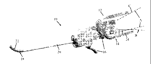
Reference is now made to Figs. 1A-1D, which illustrate a tacker 10,
constructed
and operative in accordance with an embodiment of the present invention.
Tacker 10 may include a handle 12 with a first trigger assembly 14 and a
second
trigger assembly 16. Both trigger assemblies 14 and 16 are coupled to an
articulated
applicator arm 18 which is disposed through a drive shaft 20. The first
trigger assembly
CA 02758949 2011-10-14
WO 2010/123739
PCT/US2010/031134
4
14 is used to apply rotary tacks (not shown in these figures) from a distal
end 22 of
applicator arm 18. This is accomplished by squeezing a trigger 24 towards the
body of
handle 12 (as shown by comparing Figs. 1C and 1D), as will be explained more
in detail
hereinbelow. The second trigger assembly 16 is used to bend the distal end 22
of
applicator arm 18 up (Fig. 1A) or down (Fig. 1B), as will be explained more in
detail
hereinbelow.
The central (longitudinal) axis C of handle 12 is tilted at an angle A in the
range of
about 7-25 , preferably about 110, with respect to drive shaft 20 (that is,
with respect to
the proximal portion of applicator arm 18 which remains unbent), as seen in
Fig. 1A. The
tilted configuration of handle 12 is an important ergonomic feature of tacker
10. Prior art
tackers have a pistol grip handle wherein the longitudinal axis of the handle
is aligned or
parallel with the drive shaft; there is no tilt. The prior art tacker is more
cumbersome to
use and can cause fatigue to the user. With the tilt of the present invention,
tacker 10 is
significantly more comfortable to use than prior art tackers. Another
ergonomic feature is
that trigger 24 is tilted at an angle B in the range of about 7-25 ,
preferably about 16 ,
with respect to drive shaft 20.
Reference is now made to Figs. 2A and 2B, which illustrate the inner mechanism
of tacker 10, in accordance with an embodiment of the present invention.
Trigger 24 extends from a gear wheel 25, which pivots about an axle 26. Gear
wheel 25 has a dog 27 that extends radially outwards and is biased by a
biasing device 28,
such as a coil spring. Gear wheel 25 meshes with a worm gear shaft 29, which
is the shaft
of a gear 30. Gear 30 meshes with a short gear shaft 31 of another gear 32.
Gear 32
meshes with a gear-toothed end 33 of applicator arm 18 that goes through drive
shaft 20.
Squeezing trigger 24 towards the body of handle 12 causes gear wheel 25 to
rotate,
causing worm gear shaft 29 and gear 30 to rotate, causing short gear shaft 31
and gear 32
to rotate, thereby causing gear-toothed end 33 and applicator arm 18 to
rotate. Rotation of
distal end 22 of applicator arm 18 causes a rotary tack 40 to advance off the
distal end 22
for piercing tissue (rotary tack 40 is not shown in Figs. 2A-2B but is seen in
Fig. 4).
Squeezing trigger 24 towards the body of handle 12 extends biasing device 28.
Upon releasing trigger 24, biasing device 28 pulls on dog 27, thereby causing
trigger 24
to return to its nominal position for further squeezing and application of
another rotary
tack.
CA 02758949 2011-10-14
WO 2010/123739
PCT/US2010/031134
Reference is now made to Figs. 3A-3C and 4, which illustrate the bendable
distal
end 22 of the applicator arm 18, in accordance with an embodiment of the
present
invention.
Distal end 22 is constructed of a bendable material, such as metal or plastic,
with
a series of partial annular cuts 34 formed thereon, such as by laser cutting,
for example.
The cuts 34 are formed so that distal end 22 is bendable in a first direction
(e.g., up and
down) and is generally rigid (not bendable) in a second direction
perpendicular to the first
direction (e.g., left and right). The cuts 34 are axially spaced from each
other along the
distal end 22. In the exemplary illustrated embodiment, for a given circular
cross-section
cut perpendicular to the longitudinal axis of distal end 22 at each cut 34,
partial annular
cuts 34 comprise first and second cuts 35 and 36 that each extend over an
angular range
of less than 180 on upper and lower halves, respectively, of the cross-
section of the
cylindrical distal end 22. The first and second cuts 35 and 36 terminate in
oval terminuses
37 perpendicular to the rest of the cut. These oval terminuses 37 provide
stress relief
during bending of the distal end 22.
As seen in Fig. 4, one or more rotary tacks 40 are disposed on a threaded
portion
38 of distal end 22 of applicator arm 18 (Fig, 4 shows the applicator arm 18
broken so as
to avoid showing the entire length). The coils of tacks 40 are received in the
threads of
threaded portion 38. As applicator arm 18 is rotated, tacks 40 distally
advance one-by-one
on the threads and move off the distal end 22 of applicator arm 18 and screw
into tissue
(not shown). Tack 40 may have a variety of shapes, such as circular, square or
rectangular, pentagonal or other shapes and combinations thereof. A biasing
device 39,
such as a coil spring, may be disposed at the distal end 22 to urge the tacks
40 towards the
end of the arm 18.
Pull cables 41 and 42 may be attached to the upper and lower halves,
respectively,
of distal end 22 of applicator arm 18. Pull cables 41 and 42 are manipulated
by the
operator of second trigger assembly 16 to pivot articulated applicator arm 18
to any
desired angle, such as up and straight (although the invention is not limited
to this, and
articulated applicator arm 18 can be designed for use at a variety of angles).
Reference is now made to 5A-5C. The proximal ends of each of the pull cables
41
and 42 are secured to pull blocks 43 and 44, respectively (Figs. 5A-5C
illustrate pull
block 43, but pull block 44 is similar in construction). For example, the
proximal end 45
of pull cable 41 is pulled over the rounded end of pull block 43 and secured
in a slot 46 of
a plate 47. Plate 47 is formed with teeth on its underside that mesh with
teeth formed on
CA 02758949 2011-10-14
WO 2010/123739
PCT/US2010/031134
6
the upper side of pull block 43. Plate 47 is linked to a spring-loaded piston
48 in pull
block 43. In this manner, during manufacture, plate 47 can be moved over pull
block 43
and locked at a desired position due to the meshing of the teeth and the
spring force of
spring-loaded piston 48, thus pulling pull cable 41 tightly.
Referring again to Fig. 2A, second trigger assembly 16 includes a thumb lever
50
and a finger lever 51, both of which are connected to a linkage assembly 52.
Thumb lever
50 slides in an arcuate channel 53. Linkage assembly 52 is pivotally connected
to pull
blocks 43 and 44. In the illustrated embodiment, linkage assembly 52 includes
two
linkage arms 54 and 55 which pivot about pivots 56 and 57, respectively. Upper
ends of
linkage arms 54 and 55 are pivotally connected to each other by a link 58.
Linkage arm
54 is pinned to pull blocks 43 and 44. Linkage arm 55 is connected to thumb
lever 50 and
finger lever 51.
Fig. 2A (also Fig. 1B) shows thumb lever 50 and finger lever 51 in upper
positions. In the upper position, the upper end of linkage arm 55 is thrust
forward
(distally), thereby thrusting distally the upper end of linkage arm 54. This
moves pull
block 44 backwards (proximally) and pulls pull cable 42 proximally to
straighten the
distal end 22 of applicator arm 18 (Fig. 1B). Fig. 1A shows thumb lever 50 and
finger
lever 51 in lower positions. In the lower position, the upper end of linkage
arm 55 is
pulled backward (proximally), thereby pulling proximally the upper end of
linkage arm
54. This moves pull block 43 backwards (proximally) and pulls pull cable 41
proximally
to bend the distal end 22 of applicator arm 18 upwards.
Link 58 is provided with a spring-loaded member 66 (e.g., rod with rounded
spherical ends). When thumb lever 50 and finger lever 51 are moved to their
lower
positions, spring-loaded member 66 aligns with a recess 67 formed in or at the
wall of
handle 12, whereupon spring-loaded member 66 clicks into recess 67, due to the
spring
force. The end of member 66 is rounded so that when thumb lever 50 and finger
lever 51
are moved away from their lower positions, member 66 easily is moved out of
recess 67.
The applicator arm shown in the embodiment of Figs. 1A-1B uses two pull cables
to effect the up and down bending motion.
Reference is now made to 6A-6C, which illustrate another construction of an
applicator arm 60, in accordance with another embodiment of the present
invention. In
this embodiment, only one pull cable is required.
The distal end of arm 60 includes one or more partial annular cuts 62 formed
thereon, such as by laser cutting, for example. Figs. 6A and 6B show an
embodiment with
CA 02758949 2015-09-01
7
just one partial annular cut 62, while Fig. 6C shows an embodiment with an
additional annular
cut 63 at the same axial station as annular cut 62. In the embodiment of Figs.
6A-6B, annular cut
62 extends over an angular range of more than 180 . In the embodiment of Fig.
6C, annular cuts
62 and 63 each extend over an angular range of less than 180 . The annular
cuts 62 and 63
terminate in oval terminuses 64 perpendicular to the rest of the cut. These
oval terminuses 64
provide stress relief during bending of the distal end of arm 60.
Annular cut 62 is formed such that a certain amount of material of the shaft
of arm 60 is
left to form a spring 65. Since spring 65 is part of the shaft, the spring 65
acts to straighten the
shaft when thumb lever 50 and finger lever 51 are moved from their lower
positions to their
upper positions. Thus the applicator arm 60 is bent upwards by one pull cable
(e.g., pull cable
41) but is straightened by spring 65 without need for pull cable 42.