Note: Descriptions are shown in the official language in which they were submitted.
CA 02759185 2011-10-18
WO 2010/040038 PCT/US2009/059356
1
SYSTEM AND METHOD FOR IMPROVING COMBUSTION USING AN
ELECTROLYSIS FUEL CELL
BACKGROUND OF THE INVENTION
FIELD OF THE INVENTION
[0001]The present invention generally relates to the field of combustion
engines.
More specifically, the present invention relates to a system and method for
using
an electrolysis fuel cell to enhance combustion.
DESCRIPTION OF RELATED ART
[0002] Utilizing a hydrogen fuel injection system to improve power and
efficiency
of internal combustion engines has been attempted in the past, however prior
methods of fuel injection have proved economically disadvantageous,
ineffective,
and provide no significant environmental reward.
[0003] Basic electrolysis involves two electrodes, the anode and the cathode,
submerged in an aqueous solution with an electrolyte. The electrolyte
theoretically acts as a catalyst in the electrochemical reaction as it
provides a
medium for the electrons of the direct current to flow through the water. In
actuality, however, very few electrolytes are true catalysts in electrolysis
applications. The definition of a catalyst is a chemical substance that
increases
the rate of a chemical reaction without further altering the reactants or the
products.
[0004]The most common electrolytes for hydrogen producing fuel cells are the
common bases sodium hydroxide (NaOH) and potassium hydroxide (KOH).
Both of these electrolytes are strong bases, meaning that their ionic bonds
CA 02759185 2011-10-18
WO 2010/040038 PCT/US2009/059356
2
dissociate when dissolved in water. The electrolysis splits the bonds between
the hydrogen and oxygen atoms in water. As soon as the oxygen molecules are
separated from the hydrogen in the water molecule some of the oxygen
molecules then partially bond with the electropositive ions (metals). When the
oxygen reacts with these ions, they go through a process which ultimately
results
in the productions of more water molecules, but limits the amount of oxygen
produced in a gaseous form. Theoretically, with an ideal catalyst, for each
two
units of hydrogen gas produced, one unit of oxygen gas should be produced. By
using bases as electrolytes (NaOH, KOH, etc.), the electrolytic cell increases
this
ratio of hydrogen to oxygen from 3:1 to 4:1, instead of 2:1.
[0005] Hydrogen is known to be more explosive in a combustion reaction than
oxygen; however, it is a false assumption to take for granted that in an
internal or
external combustion system that the more hydrogen the better. The present
invention utilizes hydrogen and oxygen gas in a 2:1 ratio to improve
efficiency for
any type of combustion. In combustion, hydrogen has very unique properties,
with the most important being its wide flammability range. At standard
temperature and pressure (1 ATM, 273.15 degrees Kelvin), a mixture of
hydrogen and air will burn when there is as little as 4 percent hydrogen or as
much as 75 percent hydrogen in the mixture. When hydrogen and oxygen gases
are mixed together, the flammability range increases further; from as little
as 3%
to near 99%. Injection systems are commonly scrutinized because it is said
that
the electrolysis method of hydrogen production yields a non-sufficient amount
of
gas to make any difference in combustion. The properties of hydrogen and
CA 02759185 2011-10-18
WO 2010/040038 PCT/US2009/059356
3
oxygen gases in the mixture as discussed above prove this to be incorrect;
because the gases will aide in combustion even when a mere 3% of the gases
are mixed with atmospheric gases.
[0006]The burning temperature of the gas created proves to be an effective way
to calculate the energy content of the gaseous substance. The burning
temperature represents the energy content in a given amount of gas. The
burning temperature of pure hydrogen is 2318 C. Oxygen burns slightly higher
at
temperatures climbing past 3000 C. The gases at a 2:1 ratio of hydrogen to
oxygen, however, burn at around 5000 C - much greater energy content than
either of the gases alone. This increased amount of energy is precisely why
the
effect of adding larger quantities of oxygen to hydrogen aids the combustion
process. Although burning temperatures of 5000 C may seem too hot for any
common application, temperatures only reach such levels when the gases are
burnt in 100%.
[0007] In order to ensure an even 2:1 production of hydrogen to oxygen, a true
catalyst, one which affects neither the product nor the reactant, must be
used.
The most readily available electrolyte, sodium chloride (NaCI) fits this
profile.
Sodium chloride (NaCI), common table salt, is an electrolyte that is neither
an
acid nor base, and will therefore not affect the atoms of oxygen once they are
split from their hydrogen counterparts.
[0008]The environmental impact of the adoption of a hydrogen and oxygen fuel
injection system is significant. The concept behind fuel injection systems is
to
more completely combust the given hydrocarbons. In automobiles, for example,
CA 02759185 2011-10-18
WO 2010/040038 PCT/US2009/059356
4
gasoline is the hydrocarbon. When the gasoline goes through the current
internal combustion system, a certain amount of the hydrocarbon fuel is left
over
because of incomplete combustion. There are two main reasons incomplete
combustion exists. The first source of incomplete combustion is the lack of
overall heat in the burning of the fuel. Certain fuels, gasoline for example,
require a higher burning temperature than is provided in the combustion
chamber
of the internal combustion engine. Hydrogen and oxygen gases have a higher
burning temperature, and therefore raise the temperature in the combustion
chamber for the gasoline. Because of this, the gasoline burns more completely.
[0009]The second source of incomplete combustion is found in the lack of
oxygen in the combustion chamber. Although the chemical composition of fuel is
effected by specific crude oil source, the average amount of oxygen can be
calculated for a given amount of gasoline. According to calculations,
7.0032x10⁴
grams of oxygen are needed per gram of gasoline. This means that at standard
temperature and pressure, 15.6872 mL of oxygen is needed. It can be assumed
that at sea level that 20.95% of the atmospheric gases is pure oxygen.
Therefore, when an internal combustion engine is burning a given load of one
gram, it is required to have 74.88mL of atmospheric gases. This number,
however, is often times not reached because there is insufficient air in the
combustion chamber of the cylinder. This yield yields an incomplete combustion
of fuel.
[00010] Environmentally, this means that more carbon monoxide, sulfur
hexafluoride, and other such gases are released into the environment. In
CA 02759185 2011-10-18
WO 2010/040038 PCT/US2009/059356
addition, more vaporized gasoline is released into the environment without
going
through the combustion process, which is the same thing as dumping out a given
percentage of gasoline from each tank of gas into the atmosphere.
[00011] US Patent No. 6,257,175 to Mosher et al. discloses an electrolysis
unit that generates hydrogen gas and oxygen gas from water and an electrolyte.
Mosher attempts to improve the unit's safety by attempting to collect and
isolate
the generated hydrogen and oxygen gasses. However, additional safety
concerns arise upon implementation of Mosher's concept. Injecting pure
hydrogen gas into the engine cylinder (as suggested by Mosher) may lead to the
hydrogen igniting prematurely, creating an unstable and unsafe situation,
known
by the automotive community as "knocking," which exists when any fuel ignites
prematurely. Furthermore, in Mosher the method of injection calls for a unique
installation of additional parts in the intake manifold of the car, which
raises
questions about the purpose of the invention.
[00012] It is known that vaporized fuel injection systems are beneficial to
improved efficiency for a plethora of applications; however, it is anticipated
that
newer technologies will completely eliminate the need for fossil fuels. As
such,
fuel injection systems that require a great deal of engine modifications will
prove
unworthy to consumers. If the cost to purchase an injection system is too
great
to the consumer, the technology will likely be ignored until the next
alternative
energies are developed further and made available to consumers. Therefore, it
is a priority for current fuel injection systems to be simple enough to be
reliable,
be easy to install and remove without engine modifications, and be cost
effective
CA 02759185 2011-10-18
WO 2010/040038 PCT/US2009/059356
6
immediately for the average consumer. Mosher et al. provides a system that
requires major modifications to the engine, which defeats a significant
purpose of
such an invention - namely, economic savings to the consumer. The means of
the present invention is designed for easy implementation to provide a path
for
the alternative energies of the future.
[00013] US Patent No. 6,311,648 to Larocque discloses a hydrogen-
oxygen/hydrocarbon fuel system for enhancing the efficiency of an internal
combustion engine. One of the significant shortcomings of the Larocque system
is that it relies upon gravity to refill the water level inside the
electrolytic chamber.
In real-world applications involving inclines and turbulent road conditions,
it is
likely that unintended water will be added to the electrolytic chamber. Since
maintaining a precise amount of electrolyte in the system is critical,
Larocque's
system is not well suited for real-world applications. Furthermore, Larocque
does
not account for the changing weather conditions which face real-world drivers
which could significantly affect the performance of the system.
[00014] US Patent No. 7,143,722 to Ross discloses an electrolysis cell for
supplying gaseous fuel additives to enhance combustion in a combustion engine.
However, Ross identifies potassium hydroxide (KOH) as the required electrolyte
in the system. As described, the use of KOH in Ross' system presents several
design defects and problems, among them: the severely corrosive nature of high
concentrations of KOH, the inefficiency and wasted electronic resistance that
result when using KOH, and the resulting K2O byproduct produced by the system
which is an extremely potent and toxic substance. Furthermore, the injection
CA 02759185 2011-10-18
WO 2010/040038 PCT/US2009/059356
7
system described by Ross will likely require a significant amount of time
before
being able to run at an adequate output, a situation which is impractical for
most
car drivers.
[00015] Other known prior art designs present gas-producing
electrochemical fuel cells with various shortcomings. These fuel cells
position the
anode and cathode plates as close together as possible, resulting in a great
amount of energy lost in the form of heat as well as requiring the system to
pull
through an unnecessary amount of electricity. These older designs cause
problems because many of today's cars are not produced with the high-output
alternators that other systems may require.
[00016] Thus, there remains a significant need for an electrolysis cell for
enhancing combustion which overcomes the various shortcomings and
disadvantages found in the prior art.
SUMMARY OF THE INVENTION
[00017] According to the present invention, there is provided a system and
method for improving combustion including an electrolysis cell and a hydrogen-
oxygen fuel injection system including means for generating gases, means for
maintaining gas pressure, and means for drawing and injecting gas into a
combustion reaction.
CA 02759185 2011-10-18
WO 2010/040038 PCT/US2009/059356
8
DESCRIPTION OF THE DRAWINGS
[00018] Other advantages of the present invention are readily appreciated
as the same becomes better understood by reference to the following detailed
description, when considered in connection with the accompanying drawings
wherein:
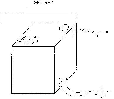
[00019] Figure 1 is a diagram representing the external architecture of the
collective enclosure of the present invention;
[00020] Figure 2 is a diagram representing the major components within
Figure 1;
[00021] Figure 3 is a schematic diagram representing the monitoring
system, on/off switch as well as main power indication LED;
[00022] Figure 4 is a diagram of the hydrogen and oxygen production unit
with a frontal view focusing on the construction of the plates;
[00023] Figure 5 is a diagram of the hydrogen and oxygen production unit
with a lateral view;
[00024] Figure 6 is a diagram of the hydrogen and oxygen production unit
with an overhead view;
[00025] Figure 7 is a diagram representing the vapor pressure equalizer
and storage unit;
[00026] Figure 8 is a schematic diagram representing the flow of water from
the main water source to the two components requiring water, the pressure-
equalizing unit and the production unit;
CA 02759185 2011-10-18
WO 2010/040038 PCT/US2009/059356
9
[00027] Figure 9A represents the system of the present invention as applied
in an external combustion setting;
[00028] Figure 9B represents the means for implementing the air
compressor to the main line of tubing in an external combustion setting;
[00029] Figure 10 is a graph representing the relationship between volts
and gas output; and
[00030] Figure 11 is a graph representing the production of hydrogen and
oxygen gases in relation to the distance between plates.
DETAILED DESCRIPTION OF THE INVENTION
[00031] The present invention provides a system and method including an
electrolysis cell and a hydrogen-oxygen fuel injection system for improving an
internal combustion engine. Through electrolysis, hydrogen as well as oxygen
gas are produced in quantities directly proportional to the energy input in
the form
of electricity. In the preferred embodiment, an internal combustion engine
such
as that found in an automobile, the oxygen and hydrogen gases are then carried
to the air intake manifold where the gases are combined with normal air and
injected into the gasoline. Although the main application for the hydrogen-
oxygen aided engine is the automobile, the present invention can be applied in
any setting where a combustion engine is called for.
[00032] The present invention generally includes a production unit in which,
under electrolytic conditions, water molecules are decomposed into their raw
elements, hydrogen and oxygen. The hydrogen and oxygen rise to the surface
of the production unit in a gaseous form. These gases are then transported to
CA 02759185 2011-10-18
WO 2010/040038 PCT/US2009/059356
the second main component, a pressure equalizer and temporary storage
container for the gaseous hydrogen and oxygen prior to injection. A water
storage vessel contains the water required for both the production unit and
the
pressure equalizer. The gases are then transferred through a given length of
tubing to the point of injection into the internal or external combustion.
This point
of injection varies depending on whether the application utilizes an internal
or
external system of combustion, as will be explained.
[00033] Figure 1 depicts the external architecture of the main enclosure of
the system of the present invention. The main enclosure of the system (1)
contains the production unit, pressure equalizer, water storage vessel, as
well as
a monitoring system that ensures the system is under ideal electrical
operating
conditions. As shown in Figure 1, the system is a cube that, in the preferred
embodiment, varies slightly in size from a 10" cube to a 12" inch cube.
Although
one set of sizes is listed specifically, the present invention allows for the
proportionate enlargement of various component of the cell and is neither
limited
nor restricted to the suggested sizes.
[00034] The production unit of the cell requires the steady flow of electric
current. In the preferred embodiment, the electricity is in the form of direct
current of electricity, as opposed to alternating current, because in order
for the
decomposition of water molecules to occur, a constant flow of electrons is
required. In the preferred embodiment, the source of this electrically is most
simply provided by the automobiles' readily available electrical system. This
electricity is ideally 12 volts, however under normal conditions may range
from
CA 02759185 2011-10-18
WO 2010/040038 PCT/US2009/059356
11
11.6 volts - 13.8 volts. This difference in voltage creates no profound
differences
in the operation of the injection system, however the greater the voltages,
the
more gases will be created.
[00035] The relationship of volts and gas output can be seen as an
exponential equation and is normally observed by the following equation,
illustrated in Figure 10: Gas output=F(v)= -.003935v2+.2858196x+ 1.90996 .
[00036] As shown in Figure 10, the production of hydrogen and oxygen
gases in an electrolytic cell is estimated by the electrical pressure measured
in
volts (v) throughout the circuit. This function is applicable to voltages from
2v-
32v.
[00037] Figure 10 further demonstrates that as voltage increases, the gas
output increases as well. Furthermore, as voltage exceeds 30 volts, the slope
of
the graph (demonstrating the rate of increase of gas output) diminishes
significantly. This is precisely why a means of voltage amplification is not
utilized. In sum, although a greater voltage will result in a greater amount
of
hydrogen and oxygen gas in an electrolytic cell, 12 volts plus or minus 3
volts will
not dramatically affect the overall means of operation for the system.
[00038] Although utilizing the automobile's pre-existing electrical system is
simple and effective, in an alternative embodiment the system is configured to
utilize DC electric current. With no major modifications to the system of the
present invention, the electrical inputs can be sought available from methods
such as photovoltaic arrays, isolated regenerative breaking, or reverse
solenoid
CA 02759185 2011-10-18
WO 2010/040038 PCT/US2009/059356
12
methods such as rear-axe[ mounted induction turbines as known to those of
skill
in the art.
[00039] Although under most imaginable operating conditions the system's
power consumption remains constant, under extreme environments an electrical
monitoring system (4) provides the means to protect the automobile's
electrical
system as well as ensuring a high level of safety is maintained for the
gaseous
production unit (depicted in Figure 3). The system consists of a voltammeter
(6)
as well as an ammeter (5). In the preferred embodiment, the monitoring system
runs of an external power supply of 3v. The circuit to power the digital read-
out
measurement devices is kept in isolation from the main circuit of the cell so
to not
interfere with the readings. The 3 volt system is designed to run using 2-AA
batteries (38), although other adequate 3 volt power supplies will suffice.
[00040] The voltammeter is preferably of the digital read-out variety and
ideally consists of a 4-digit LED display. It is necessary to have a DC
voltammeter that displays accurate readings from 0-20 volts, or possibly
higher
depending on whether an additional main external power source is utilized.
[00041] The ammeter is also preferably of the digital read-out variety and
ideally consists of a 4-digit LED display. It is necessary to have a DC
ammeter
that displays accurate readings from 0-20 amperes.
[00042] The system includes a master power switch, which is preferably a
rocker-type 2-path switch easily accessible to the user. The switch is
designed
to be active at all times, however power will only be supplied while the
engine is
CA 02759185 2011-10-18
WO 2010/040038 PCT/US2009/059356
13
under operation. This master power switch is directed towards use as an
emergency on-off toggle.
[00043] The amperage is the main factor that is important to monitor. If the
amperes exceed 10A, there are two main features this protect the circuit from
over loading, depicted in Figure 3. Initially, the ideal safety mechanism is a
time-
delay fuse (7, 8). The fuse is designed to break at 10A, with a 90 second
delay.
Therefore, if the system regains normal power consumption (under 10A) the
system will continue under normal operation. In addition, primarily in case
the
time-delay fuse fails to work as designed, a buzzer (40) will activate. The
buzzer
will be of sufficient volume so as to be heard by the user. Although other
varieties of buzzers will suffice, preferably a high-pitched buzzer with
intervals of
seconds is required. It is then implicated that the user will manually use the
on-
off toggle rocker switch to manually cut power to the system.
[00044] The monitoring system of the present invention is designed with
automation in mind, requiring no action by the user even if a failure in the
system
is present, while also incorporating the benefits of having a manual override.
[00045] The central component of the present invention is the unit (14) for
producing hydrogen and oxygen gases, as shown in Figure 2. The unit (14)
contains a given volume of electrolytic solution directly proportionate to the
dimensions of the overall cell. Figure 4 demonstrates a lateral side view of
the
production unit. In the preferred embodiment, the unit is a rectangular prism
consisting of eight electrodes (22) submerged in the electrolytic solution. In
the
preferred embodiment, the electrodes are made of a high-grade stainless steel.
CA 02759185 2011-10-18
WO 2010/040038 PCT/US2009/059356
14
[00046] In the preferred embodiment, the exact spacing between electrodes
is crucial to the overall efficiency of the cell. There are several factors,
which
affect the spacing between electrodes within the production unit:
[00047] As the distance between electrodes decreases, amperes increases;
[00048] As the distance between electrodes decreases, more heat is given
off in the form of water vapor in a linear system of equations; and
[00049] As the distance between electrodes decreases, the production of
hydrogen and oxygen increases, however the increase is quadratic and its
implications are seen in Figure 11.
[00050] In light of the above, the spacing of the electrodes is crucial as it
is
important to produce the maximum amount of gas, however this must be done
without pulling through too many amperes and without giving off excess heat.
[00051] Figure 11 shows the production of hydrogen and oxygen gases in
relation to the distance between plates. The x-axis represents the spacing, in
which each positive integer corresponds to an exact distance. The y-axis is
the
volume of gases produced in milliliters in a 75 second time interval. The
electrodes used were constructed out of 316-stainless steel. The electrolyte
was
a .2 Molar sodium chloride solution.
[00052] The data below (Table 1) offers the experimental explanation of the
spacing of electrodes in relation to one another. At the distance of 1 inch,
the
resulting factors reach maximum efficiency. It is at 1 inch that a high level
of
hydrogen and oxygen gases are produced, yet the amperage remains below 1
CA 02759185 2011-10-18
WO 2010/040038 PCT/US2009/059356
amp and the heat (not shown) remains low enough so as to not loose any
quantity of water due to water vapor.
D Distance Output T1 Output Output Average
Val (in.) (mL) T2 T3 (mL) Amps
1 3 98 98 97 97.67 0.102
2 2.75 115 111 113 113 0.146
3 2.5 128 131 132 130.333 0.177
4 2 139 138 139 138.67 0.208
5 1.75 152 149 153 151.33 0.214
6 1.5 163 160 160 161 0.269
7 1.45 184 183 187 184.67 0.308
Q I A .Ina .InC -1 nn .1 nc c7 n 7t
V 1 .T IOU I J J 100 I JV.V / V.J! V
9 1.35 212 214 211 212.3 0.399
10 1.3 224 227 225 225.3 0.442
11 1.25 247 245 247 246.3 0.455
12 1.2 263 269 265 265.67 0.473
13 1.15 282 281 283 282 0.682
14 1.1 311 314 313 312.67 0.784
15 1.05 333 336 332 333.67 0.887
16 1 351 349 348 349.3 0.987
17 0.95 353 354 357 354.67 1.221
18 0.9 355 357 354 355.3 1.379
19 0.85 357 359 359 358.3 1.947
0.8 359 360 360 359.67 2.441
21 0.75 361 362 359 360.67 2.908
22 0.7 359 363 362 361.3 3.436
23 0.65 363 365 362 363.3 3.79
24 0.6 366 368 369 367.67 4.005
0.55 371 371 372 371.3 4.238
26 0.5 372 374 373 373 4.666
27 0.45 375 377 375 375.67 4.709
28 0.4 381 382 382 381.67 5.102
29 0.35 382 383 380 381.67 5.42
0.3 384 383 385 384 5.824
Table 1
[00053] The 1-inch spacing is clearly seen in Figure 4, which is the side
view of the production unit. In the preferred embodiment, the enclosure (41)
is
made out of a strong-heat resistant material, preferably molded acrylic or
polyvinylchloride, although other materials sharing similar characteristics
may be
CA 02759185 2011-10-18
WO 2010/040038 PCT/US2009/059356
16
used. From Figure 4, the elevation of the electrode harnessing system (20, 26)
from the bottom surface of the cell is clearly visible. This raises the
electrodes
from the bottom of the cell, which allows for the movement of electrolytic
solution
that is essential during operation on an incline, and for other situations.
[00054] The electrodes are raised off the bottom of the cell to allow for the
even distribution of electrolytic solution and water when the water-feeding
ports
add water to the cell. Along each sidewall lays a strip of the material of
which the
enclosure is constructed (41). The strips (20) run the length of the unit and
protrude a sufficient length from the side so as to ensure no slippage of
electrodes (22). The bottom strip (20) ensures that the electrodes do not move
vertically, and the same concept applies vertically in the unit as well (26).
The
grooves (26) may either protrude from the side or may be negative space,
depending on the design of the specific component. In either scenario, the
grooves (26) should be a distance apart equal to the thickness of electrodes
(22).
Figure 5 depicts a lateral view of this arrangement. It is the combination of
both
the bottom strip (20) and the vertical laying grooves (26) that ensure no
movement of the electrodes occurs, even under less-than-ideal conditions.
[00055] Figure 6 represents a detailed side profile of the electrode (22)
incorporated within the present invention. The strip of material that contains
the
electrodes vertically (20) is demonstrated from the side view. The electrode
includes a notch (25) on the top of the electrode which contains a punched
hole
(24) which enables a method of electrical combination of charges between like
electrodes. In the preferred embodiment, the hole (24) is designed to be .25in
in
CA 02759185 2011-10-18
WO 2010/040038 PCT/US2009/059356
17
diameter through which a rod of stainless steel (44, 45), or a metal of
similar
conductance, completes the flow of electrons to the other electrodes of a
similar
charge. There exists one rod for each charge present, therefore, two separate
fuel connecters. This rod is the means through which the electricity from the
external power source is introduced to the hydrogen and oxygen production
unit.
[00056] Turning now to Figure 2, the present invention includes wires (10,
11) which carry the electric current to the production unit (14). In the
preferred
embodiment, the wires (10, 11) are comprised of insulated copper wiring (12-
gauge wire is preferable, however lower-gauge wiring is also sufficient). The
wires then connect to the exterior of the cell where the current is continued
to the
connection rods (44,45). Internally in relation for the outer enclosure,
however
externally in relation to the production unit in its entirety, the wires are
then
connected to the electrical rods (44,45) are previously described. These are
to
be connected by means of a standard electrical terminal with a diameter equal
to
that of the fuel rod, .25inches. The production unit (14) is the element in
which
the hydrogen and oxygen vapors are created from the decomposition reaction of
water. As described in detail above, the space between electrodes controls the
amount of electricity running through the unit, thereby ensuring the system's
safe
operation. When activated with electricity, the unit begins to produce the
gaseous forms of hydrogen and oxygen gas. As represented in Figure 4, the gas
bubbles rise to the surface of the electrolytic solution where it is fed into
the gas
transport conduit (16). This conduit transfers the gases from the production
unit
(14) to the pressure-equalizing unit (15) by means of tubing (18). The conduit
CA 02759185 2011-10-18
WO 2010/040038 PCT/US2009/059356
18
may vary in size and diameter, but a secure attachment to the tubing is
required
so as to avoid any possible leakage of gases from this point. In the preferred
embodiment, the tubing (18) is composed of vinyl, however polyethylene tubing
also proves sufficient. In the preferred embodiment, the tubing at this point
has a
diameter of 3/8th of an inch.
[00057] In the preferred embodiment, the diameter of the tube is critical
since wider tubing may not allow the gases to flow to the pressure equalizer.
In
order for the gases to transfer correctly, a positive pressure must exist in
the
tube. The wider the tube, the more gas from the production unit is required to
force the gases to continue to the pressure equalizer (15). Therefore, the
inside
diameter of the tubing at this section of the system should preferably be
3/8th of
an inch.
[00058] Tubing (18) from the production unit (14) to the pressure-equalizing
unit (15) is attached with the same type of connection as used in the gas
transport conduit (16). Figure 7 depicts the vapor pressure equalizer and
storage
unit. The pressure-equalizing conduit (17) should preferably be located on the
side of the pressure-equalizing unit (15), preferably on the top 1/4th of the
unit.
Inside the unit lays another set of tubing connected through conduit (17).
This
tubing is constructed of a solid material, such as polyvinylchloride. The
conduit
(29) after being attached to (17) then makes a 90-degree turn to continue down
to near the bottom of the pressure-equalizing unit.
[00059] The most important aspect of the pressure-equalizing unit is the
water (46), which it contains. The source of the water is the water storage
tank
CA 02759185 2011-10-18
WO 2010/040038 PCT/US2009/059356
19
(30) shown in Figure 8. The bottom third of the pressure equalizing unit
contains
water. Unlike the production unit, this water does not contain an electrolytic
solution because no electrochemical reactions occur therein. The purpose of
the
water is to allow the gaseous hydrogen and oxygen gases to rise from the end
of
the gas-transport conduit to the top of the pressure-equalizing unit. The
gases,
created in the production unit (14) then flow through the gas transport
conduit
(29) and bubble up (47) through the water. Once the gases bubble through the
water, they are free to float around in the upper two-third of the unit (55).
It is in
this area (55) the gases remain until demanded by the combustion chamber of
the specific application.
[00060] It should be noted that the system and method of the present
invention is applicable to both internal and external combustion systems. The
following description will first illustrate the system's configuration and
operation in
an internal combustion application, followed by an illustration of an external
combustion application of the present invention.
[00061] As described previously, all internal combustion engines require a
sufficient amount of air in order to carry out the combustion reaction to
drive the
engine's pistons. Because of this, all internal combustion engines are
designed
to create negative pressure (a vacuum) to inhale air from an outside source in
an
attempt to provide the attempted combustion with a certain amount of oxygen.
The end result of this process is a strong flow of air from outside of the
combustion chamber to the inside. This vacuum is utilized by the present
invention to ensure that the proper amounts of gaseous hydrogen and oxygen
CA 02759185 2011-10-18
WO 2010/040038 PCT/US2009/059356
are injected into the combustion chamber. The present invention utilizes the
air-
flow already present in the combustion engine together with oxygen sensors to
ensure that the proper amount of air is injected. Utilizing the engine's
vacuum
ensures that there can never be too much hydrogen and oxygen in the injection
chamber (which would risk an explosion). The engine sucks in only the amount
of air that it requires.
[00062] When the engine is demanding air via the negative pressure in the
air intake manifold, this creates suction in the tubing from the pressure
equalizing
unit to the air intake itself. The suction then makes its way to into the
pressure-
equalizing unit, wherein for each unit of negative pressure that is applied to
the
unit, the unit releases a given quantity of hydrogen and oxygen through the
release conduit (21) through the final length of tubing (19), which feeds
directly
into the air intake manifold as shown in Figure 2.
[00063] At this point in the process, the hydrogen and oxygen enhance the
engine's combustion of the gasoline. The two main factors that control the
efficiency of any combustion reaction are the amount of oxygen present in the
atmosphere surrounding the combustion and the heat of the combustion. The
present invention is directed towards altering both of these factors, thereby
improving the efficiency and facilitating a more complete combustion of fuel.
[00064] The amount of oxygen joining the gas in the combustion chamber is
critical in calculating the efficiency of the combustion. The standard
composition
of atmospheric gases at sea level is 20.95% oxygen. Calculated from basic
stoichiometric calculations, this means that per gram of fuel combusted, the
CA 02759185 2011-10-18
WO 2010/040038 PCT/US2009/059356
21
combustion chamber should ideally contain at least 78.436 mL of atmospheric
gases. Although this number may be reached at times, there is no guarantee
that any volume of atmospheric gases will contain the appropriate amount of
oxygen. Therefore, the present invention directly injects oxygen as an
additive,
to ensure that the oxygen is the excess reactant in the chemical equation.
Doing
so ensures that the given fuel will not be limited in combustion because of
the
lack of oxygen. Instead of injecting normal air that requires 78.463 mL of
gas,
utilizing the system of the present invention requires only a minimal amount
of
gas to be added to the combustion chamber - a mere 15.6 mL, if pure oxygen is
injected. Doing so allows smaller engines to output a greater amount of torque
per cubic centimeter (CC) of engine occupancy.
[00065] The second way in which the present invention aids the combustion
process is by temporarily raising the heat in the combustion chamber. At
times,
when too little heat is present in relation to the heat needed for complete
combustion for a certain fuel, excess reactants will form. For example, when
normal gasoline is burned in a standard automobile, a given amount of carbon
dioxide is produced. This carbon dioxide is present because too low a
temperature was present in the combustion chamber, ultimately resulting in the
production of carbon monoxide gases.
[00066] The present invention offers hydrogen as an additive to provide a
solution for this source of inefficiency. Hydrogen gas, when in combination
with
oxygen, has a significantly higher burning temperature than gasoline.
Therefore,
in a combustion engine when the spark plug provides the spark for combustion,
CA 02759185 2011-10-18
WO 2010/040038 PCT/US2009/059356
22
the hydrogen and the oxygen burn at the same time as the gasoline. When the
hydrogen and oxygen combust, however, the temperature is raised. In doing so,
the higher burning temperatures raise the temperature in the chamber, thereby
resulting in a higher level of efficiency for the internal combustion
reactions.
[00067] Although the properties of enhancing combustion remain constant
for external combustion reactions, the method of injection differs
dramatically.
Unlike internal combustion engines, such as automobiles, external combustion
chambers provide very little vacuum pressure. The point of combustion is more
open and allows for the natural circulation of air. Therefore, in order to
implement the system of the present invention, another source of pressure must
be incorporated in order to ensure that sufficient amounts of gaseous hydrogen
and oxygen gases are present at the point of combustion.
[00068] Figure 9A represents a method of injection for external combustion
applications. The main unit (1) is present and remains the most important
aspect
of the system. After the gas is created in the production unit (14) and
travels to
the pressure-equalizing unit (15) the gas requires a source of negative
pressure,
or a vacuum. In the preferred embodiment, this source is a small-scale air
compressor (50). The air compressor forces a given amount of atmospheric
gases through the tubing (49) to the point of combustion (52). When applied to
the same tubing as the main unit (1) connects to, vacuum pressure is created.
Therefore, the gases are released from the pressure-equalizing unit (15) and
sent through the tubing (49) to the external combustion chamber (54). The
means for implementing the air compressor (50) to the main line of tubing (49)
is
CA 02759185 2011-10-18
WO 2010/040038 PCT/US2009/059356
23
shown in detail in Figure 9B. This demonstrates that the airflow from the air
compressor (55) is connected at an angle to the current tubing (56). This
ensures that a sufficient amount of gases are drawn from the pressure-
equalizing
unit (15).
[00069] The external combustion chamber (54) contains the key
components for any external combustion application. Present is a fuel line
(51)
which transports the given fuel to the point of combustion (52). Once ignited,
the
point of combustion (52) maintains a constant flame. When the combustion
begins, the user activates the present invention. This begins the production
of
hydrogen and oxygen gases. The air compressor (50) then creates the vacuum
pressure required to transport all necessary hydrogen and oxygen gases to the
point of combustion (52). As described above, this aids the combustion by both
ensuring proper levels of oxygen and increasing the heat of combustion by the
burning of hydrogen gases.
[00070] As previously mentioned, the system of the present invention
includes a method of water distribution to the various components of the
injection
system. The two units requiring a set amount of water are the production unit
(14) and the pressure-equalizing unit (15). In the preferred embodiment, as
depicted in Figure 8, there exists one main tank for the water (30) that is
accessible by a removable cap (2). The cap should preferably be child-tamper
proof to avoid the possibilities of water leaking. To control the amount of
water
allowed into each unit, the piping (32, 34) is inserted at a specific distance
from
the bottom of each respective unit. For example, a higher water level is
required
CA 02759185 2011-10-18
WO 2010/040038 PCT/US2009/059356
24
in the production unit (14) in relation to the pressure-equalizing unit;
therefore the
pipe (32) is inserted at a greater distance from the bottom of the unit
itself. The
pipe connecting the water from the main storage tank (30) to the pressure-
equalizing unit (15) is at a distance approximately 1/3 from the bottom of the
unit.
As an added safety precaution, butterfly valves (31, 33) are present on each
of
the pipelines providing water to the various components. Although not readily
accessible to the user in the preferred embodiment, in the case of required
maintenance or further testing, the valves (31,33) will provide the means
necessary to precisely control the amount of water flow.
[00071] The invention has been described in an illustrative manner, and it is
to be understood that the terminology that has been used is intended to be in
the
nature of words of description rather than of limitation.
[00072] Obviously, many modifications and variations of the present
invention are possible in light of the above teachings. It is, therefore, to
be
understood that within the scope of the described invention, the invention may
be
practiced otherwise than as specifically described.