Note: Descriptions are shown in the official language in which they were submitted.
CA 02759970 2011-11-30
AUTOMATIC BLOWER CONTROL
TECHNICAL FIELD
[0001] This application is directed, in general, to HVAC
systems, and more specifically to control of a blower motor for
use in an HVAC system.
BACKGROUND
[0002] Commissioning an HVAC (heating ventilating and air
conditioning) system typically requires the services of a
service technician to establish proper operation. One aspect of
operation is the rate of airflow provided by the HVAC system.
When the HVAC system is a variable air volume (VAV) system, the
system commissioning typically includes configuring the HVAC
system to produce the proper airflow at each of two or more
airflow levels. This process is often laborious, and therefore
expensive and time consuming.
SUMMARY
[0003] One embodiment provides a blower system that includes
a blower motor mechanically coupled to a blower. The blower is
configured to generate an airstream having an airflow rate. An
inverter is in electrical communication with the motor. The
inverter is configured to provide a motor drive signal to the
motor. A flow rate calculator is configured to determine a
-1-
CA 02759970 2011-11-30
calculated airflow rate from motor operating parameters using a
mathematical model of the airflow rate.
[0004] Another embodiment provides a method of controlling a
blower motor connected to a blower. The method includes
providing motor operating parameters of a blower motor to a unit
controller. The unit controller is configured to employ a
mathematical model of airflow from the blower to determine a
motor speed control signal based on the motor operating
parameters. The speed control signal is provided to an inverter.
A motor drive signal from the inverter is provided to the blower
motor based on the speed control signal.
[0005] In another embodiment a blower unit controller is
provided. The blower unit controller includes an input and an
output. The input is configured to receive motor operating
parameters. The output is configured to provide a motor speed
control signal to an inverter. A memory is configured to store a
mathematical model of airflow produced by a blower motor to
relate a blower motor speed to the motor operating parameters. A
processor is configured to produce the speed control signal
based on the mathematical model.
[0006] Another embodiment provides a method of manufacturing
an HVAC blower motor system. The method includes providing an
inverter configured to produce a motor drive signal in response
to a motor speed control signal. The motor drive signal is
-2-
CA 2759970 2017-04-21
connected to a blower motor oonfig;_ired to generate an airflow.
An airflow calculator receives motor operating parameters. The
airflow calculator is configured to determine a calculated
;Airflow using a mathematical model of the airflow as a function
of the motor operating parameters.
[0007] Another
embodiment provides a method of indirectly
determining external static pressure in an HVAC system. The
method includes providing motor eperatino parameters of a blower
motor to an external static pressure calculator. A mathematical
model of external static pressure produced by the blower motor
is employed within the calculator to determine from the motor
operating parameters a calculated external static pressure
within an air duct coupled to a blower driven by the blower
motor. The calculated external stati.c pressure is communicated
to a remote entity.
In one aspect, there is provided a blower system, comprising:
a blower motor mechanically coupled to a blower configured
to generate an airstream having an airflow rate;
an inverter in electrical communication with said motor and
configured to provide a motor drive signal to said motor; and
a flow rate calculator configured to determine a calculated
airflow rate from motor operating parameters of said blower motor
using a mathematical model of said airflow rate, wherein the
mathematical model is configured to calculate the airflow rate as
a function of at least one of frequency, voltage, and power of the
inverter.
-3-
CA 2759970 2017-04-21
In one aspect, there is provided a method of controlling a
blower motor connected to a blower, the method comprising:
providing motor operating parameters of said blower motor to
a unit controller;
employing within said unit controller a mathematical model
of airflow from said blower to determine a motor speed control
signal based on said motor operating parameters;
providing said speed control signal to an inverter; and
providing a motor drive signal from said inverter to said
blower motor based on said speed control signal, wherein the
mathematical model is configured to calculate an airflow rate as
a function of at least one of frequency, voltage, and power of the
inverter.
In one aspect, there is provided a blower unit controller,
comprising:
an input configured to receive motor operating parameters;
an output adapted to provide a motor speed control signal to
an inverter;
a memory configured to store a mathematical model of airflow
produced by a blower motor, the mathematical model being configured
to relate a motor speed to said motor operating parameters; and
a processor configured to produce said speed control signal
based on said mathematical model, wherein the motor operating
parameters include frequency, voltage, and power of a motor drive
signal.
In one aspect, there is provided a method of manufacturing
an HVAC blower motor system, the method comprising:
-3a-
providing an inverter configured to produce a motor drive
signal in response to a motor speed control signal;
connecting said motor drive signal to a blower motor
configured to generate an airflow; and
receiving motor operating parameters into an airflow
calculator configured to determine a calculated airflow using a
mathematical model of said airflow as a function of said motor
operating parameters, wherein the motor operating parameters
include frequency, voltage, and power of a motor drive signal.
In one aspect, there is provided a method of indirectly
determining external static pressure in an HVAC system, the method
comprising:
providing motor operating parameters of a blower motor to an
external static pressure calculator;
employing within said calculator a mathematical model of
external static pressure produced by said blower motor to determine
from said motor operating parameters a calculated external static
pressure within an air duct coupled to a blower driven by said
blower motor, wherein the motor operating parameters include
frequency, voltage, and power of a motor drive signal;
calculating a coefficient weighting contribution of the
external static pressure; and
communicating said calculated external static pressure and
the calculated coefficient to a remote entity.
In one aspect, there is provided a blower system, comprising:
a blower motor mechanically coupled to a blower configured
to generate an airstream having an airflow rate;
-3b-
CA 2759970 2017-08-25
an inverter in electrical communication with said motor and
configured to provide a motor drive signal to said motor;
a flow rate calculator configured to determine a calculated
airflow rate from motor operating parameters of said blower motor
using a mathematical model of said airflow rate;
wherein the mathematical model is configured to calculate
the airflow rate as a function of at least one of frequency,
voltage, and power of the inverter and includes a static pressure
term determined from the airsteam.
In one aspect, there is provided a method of controlling a
blower motor connected to a blower, the method comprising:
providing motor operating parameters of said blower motor to
a unit controller;
employing within said unit controller a mathematical model
of airflow from said blower to determine a motor speed control
signal based on said motor operating parameters;
providing said speed control signal to an inverter;
providing a motor drive signal from said inverter to said
blower motor based on said speed control signal;
wherein the mathematical model is configured to calculate an
airflow rate as a function of at least one of frequency, voltage,
and power of the inverter and includes a static pressure term
determined from the airflow.
In one aspect, there is provided a blower unit controller,
comprising:
an input configured to receive motor operating parameters;
-3c-
CA 2759970 2017-08-25
an output adapted to provide a motor speed control signal to
an inverter;
a memory configured to store a mathematical model of airflow
produced by a blower motor, the mathematical model being configured
to relate a motor speed to said motor operating parameters, wherein
the mathematical model includes a static pressure term determined
from the airflow; and
a processor configured to produce said speed control signal
based on said mathematical model, wherein the motor operating
parameters include frequency, voltage, and power of a motor drive
signal.
In one aspect, there is provided a method of manufacturing an
HVAC blower motor system, the method comprising:
providing an inverter configured to produce a motor drive
signal in response to a motor speed control signal;
connecting said motor drive signal to a blower motor configured
to generate an airflow;
receiving motor operating parameters into an airflow calculator
configured to determine a calculated airflow using a mathematical
model of said airflow as a function of said motor operating
parameters, wherein the mathematical model includes an external
static pressure term determined from the airflow; and
wherein the motor operating parameters include frequency,
voltage, and power of a motor drive signal.
In one aspect, there is provided a method of indirectly
determining external static pressure in an HVAC system, the method
comprising:
-3d-
CA 2759970 2017-08-25
providing motor operating parameters of a blower motor to an
external static pressure calculator;
employing within said calculator a mathematical model of
external static pressure produced by said blower motor to determine
from said motor operating parameters a calculated external static
pressure within an air duct coupled to a blower driven by said blower
motor, wherein the motor operating parameters include frequency,
voltage, and power of a motor drive signal;
calculating a coefficient weighting contribution of the
external static pressure; and
communicating said calculated external static pressure and the
calculated coefficient to a remote entity.
BRIEF DESCRIPTION
[0008] Reference is now made to the following descriptions
taken in conjunction with the accompanying drawings, in which:
[0009] FIG. 1 illustrates a building with a number of rooftop
HVAC units located thereon;
[0010] FIG. 2 illustrates a blower motor system applicable to
the HVAC units of FIG. 1, including an inverter and an airflow
-3e-
CA 2759970 2017-08-25
CA 02759970 2011-11-30
= calculator configured to calculate an airflow based on motor
operating parameters received from the inverter;
[0011] FIG. 3 illustrates a blower motor system applicable to
the HVAC units of FIG. 1, including an inverter and an HVAC unit
controller incorporating the airflow calculation functionality
of FIG. 2;
[0012] FIG. 4 illustrates an alternate embodiment of a blower
motor system in which motor instrumentation provides motor
operating parameters to the unit controller;
[0013] FIG. 5 illustrates a functional block diagram of the
unit controller of FIG. 3;
[0014] FIG. 6 illustrates an embodiment of a system
configured to implement the block diagram of FIG. 4;
[0015] FIGs. 7 and 8 are correlation plots for two examples
of measured and calculated airflow of a test HVAC system, where
the airflow is calculated according to embodiments of the
disclosure;
[0016] FIG. 9 is a method of configuring an HVAC unit
controller with a mathematical airflow model;
[0017] FIG. 10 is a method of controlling a blower motor;
[0018] FIG. 11 is a method of manufacturing an HVAC blower
motor system;
[0019] FIGs. 12A and 12B illustrate example pulse-width-
modulation signals; and
-4-
CA 02759970 2011-11-30
[0020] FIG. 13 illustrates a method of indirectly determining
an external static pressure in an HVAC system.
DETAILED DESCRIPTION
[0021] This disclosure benefits from the recognition by the
inventor that commissioning an HVAC system that includes a
blower may be advantageously simplified by employing a unit
controller that includes a mathematical model of airflow rate
produced by the blower. (Herein airflow rate may be referred to
simply as airflow for brevity.) For example, a conventional
rooftop HVAC system (rooftop unit, or RTU) typically includes a
blower motor to drive a blower that circulates conditioned air
in a building such as a retail store. The RTU may be a variable
air volume (VAV) system, which may be configured to produce
different airflow rates for different cooling or heating loads.
The conventional system typically requires a trained technician
to set the speed of the blower motor to a value that results in
a rate of airflow desired by a customer for each desired airflow
setting of the VAV. Such customization typically entails
significant cost, which may be considerable when multiplied over
many installed units in a large building or multiple buildings.
[0022] Advantageously, embodiments of the present disclosure
provide systems and methods to obviate the need for such
customization. A mathematical model is determined that describes
-5-
CA 02759970 2011-11-30
the airflow produced by the blower as a function of various
operating parameters of the blower motor. A unit controller of
one or more HVAC systems may be configured with the mathematical
model at a manufacturing site prior to delivery, or remotely
configured after installation. The HVAC systems may then be
installed without the need for flow customization by the
installer. The mathematical model may be empirically determined
for a particular system design and/or building configuration,
and may even be customized to a particular HVAC unit if desired.
[0023] FIG. 1 illustrates a building 110 having multiple
placements of a RTU 120 located thereon. The RTUs 120 may be
multiple instances of a same HVAC system, but need not be. One
instance of the RTUs 120 is illustratively connected to an air
duct 130 to route conditioned air to desired locations within
the building 110, and to route return air back to the RTU 120.
The air duct 130 imposes a resistance on the flow of air within.
The resistance is in part a function of the cross-sectional area
and length of the duct, the velocity of the airflow, and the
presence of options such as filters.
[0024] In many cases the air duct 130 may be of a standard
design. For instance, a retail company may have multiple stores
with a particular layout, and thus the air duct 130 may be
closely similar among different store locations. Within a
particular location, a standard ductwork design may be
-6-
CA 02759970 2011-11-30
determined and placed at multiple locations within the store,
thereby spreading design costs over the several placements.
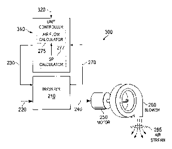
[0025] FIG. 2 illustrates an embodiment of a blower system
200. The blower system 200 may be present in each instance of
the RTU 120. The blower system 200 includes an inverter 210 that
receives power 220 and a motor speed control signal 230. In
response to the motor speed control signal 230 the inverter 210
provides a modulated motor drive signal 240 to a blower motor
250. The blower motor 250 may be, e.g. a conventional
alternating current (AC) or electronically commutated motor
(ECM) motor. The blower motor 250 is coupled to a blower 260
that produces an airstream 265 when turned by the blower motor
250.
[0026] Those skilled in the pertinent art are familiar with
blower motors and inverters. In brief summary, the inverter 210
may produce a pulse-width modulated (PWM) signal to the blower
motor 250 that has a pulse frequency and amplitude. The inverter
210 typically modulates the PWM signal by changing the
amplitude, frequency and duty cycle of voltage pulses delivered
to the blower motor 250, thereby controlling the speed of the
blower motor 250.
[0027] FIGs. 12A and 12B illustrate for reference
characteristics of a PWM signal that may be sent from the
inverter 210 the blower motor 250. In FIG. 12A, a PWM signal
_7_
CA 02759970 2011-11-30
includes a portion with a first frequency fi and a second lower
frequency f2. In FIG. 12B a PWM signal includes a portion with a
first voltage Vi and a second greater voltage V2. The power of
the PWM signal may be determined from the integrated product of
the voltage and current of the PWM signal.
[0028] Returning to FIG. 2, the airstream 265 has an
associated airflow rate. The inverter 210 provides inverter
feedback 270 to an airflow calculator 275. The inverter feedback
270 includes motor operating parameters of the blower motor 250,
such as the amplitude, frequency and duty cycle of the motor
drive signal 240. Those skilled in the art will appreciate that
these are nonexclusive examples of the type of feedback that
inverter 210 may provide.
[0029] The
airflow calculator 275, described in detail below,
produces a calculated airflow 280. The calculated airflow 280
may provide for closed-loop feedback to the inverter 210. In the
illustrated embodiment, the calculated airflow 280 drives a
display 285 that indicates the value of the airstream 265 as
calculated by the airflow calculator 275 from the inverter
feedback 270. An operator 290 may use the information presented
on the display 285 to adjust a speed controller 295 to produce a
desired airstream 265 for one or more desired airflow rates.
Because the airflow is determined without direct measurement of
the speed of the blower motor 250 or the airstream 265, the
-8-
CA 02759970 2011-11-30
feedback provided via the inverter feedback 270 is referred to
herein and in the claims as "indirect feedback." In some
embodiments the calculated airflow 280 is communicated to a
remote entity such as a remote monitoring facility 299. Such an
entity may remotely collect data from numerous HVAC systems to
monitor proper operation and/or efficiency of the systems.
Communication may be by any means, Including telephone system,
the internet and/or wireless link.
[0030] The inverter 210 in principle may vary the power
output of the blower motor 250 continuously from 0% to 100% of
its rated power. In practice, the inverter 210 may be configured
to control the speed of the blower motor 250 to one of two or
more predetermined levels. For example, some VAV HVAC
applications include seven predetermined levels.
[0031] FIG. 3 illustrates another embodiment of a blower
system, generally designated 300. The blower system 300 retains
many of the elements of the blower system 200, but replaces the
operator 290 with a unit controller 310. In the illustrated
embodiment the unit controller 310 incorporates the
functionality of the airflow calculator 275. In some
embodiments, as described below, the unit controller 310
includes an external static pressure calculator 277. The unit
controller 310 receives the inverter feedback 270, employs the
airflow calculator 275 to indirectly determine a flow rate of
-9-
CA 02759970 2011-11-30
the airstream 265, and provides the motor speed control signal
230. The airflow calculator 275 may use a calculated external
static pressure in its operation. The unit controller 310 may
dynamically adjust the motor speed control signal 230 to
maintain a desired airflow as indirectly determined by the
airflow calculator 275.
[0032] FIG.
4 illustrates another embodiment of a blower
motor system generally designated 400. In this embodiment the
blower motor 250 includes motor instrumentation 410 to provide
motor feedback 420 to the unit controller 310. The motor
feedback 420 may be in addition to or in lieu of the inverter
feedback 270. Such instrumentation may include, e.g.,
conventional encoders, magnetic switches, optical devices, or
other sensors able to determine motor operating parameters of
the blower motor 250, such as the RPM, torque, frequency,
voltage and/or power of operation thereof. Such instrumentation
may be advantageous when the inverter 210 is not configured to
provide the inverter feedback 270, or if direct measurement of
the motor operation is desired to meet other system-level design
objectives. In this embodiment the feedback to the unit
controller 310 is directly from the blower motor 250 rather than
by proxy from the inverter 210. Such feedback is referred to
herein and in the claims as direct feedback.
-10-
CA 02759970 2011-11-30
[0033] In conventional practice, the airstream 265 for a
given installation is typically calibrated for each RTU 120 for
each speed setting of the blower motor 250. For example, the
inverter 210 may be conventionally configured to output one of
seven control levels. A mechanical connection between the blower
motor 250 and the blower 260 may be adjusted to result in the
airflow desired for each control level. Such adjustment may
conventionally be made, e.g. by adjusting a pulley diameter in a
drive train between the blower motor 250 and the blower 260.
[0034] In contrast to conventional practice, the unit
controller 310 implements a mathematical model denoted G that is
configured to translate the blower demand 320 to the motor speed
control signal 230 to directly result in the desired airflow for
each setting. The mathematical model receives as inputs, via the
inverter feedback 270 or motor feedback 420, one or more
variables that describe the operation of the blower motor 250.
The model then produces, as output, a calculated estimate of the
airflow associated with the values of the various inputs.
[0035] FIG. 5 illustrates one embodiment of a functional
block diagram of the unit controller 310. An airflow calculation
block 510 receives feedback parameters 520 (e.g. inverter
feedback 270 and/or motor feedback 420) and computes a
calculated airflow 530 based on the mathematical model G. The
calculation block 510 may be implemented using analog circuitry
-11-
CA 02759970 2011-11-30
and/or digital logic. A comparator 540 receives the blower
demand 320 and the calculated airflow 530, and produces the
motor speed control signal 230. The motor speed control signal
230 may be conditioned as necessary to interface with the
inverter 210.
[0036] By comparing the calculated airflow 530 to the blower
demand 320, the unit controller 310 may indirectly monitor the
actual airstream 265 and adjust the motor speed control signal
230 to result in the airstream 265 selected by the blower demand
320. Thus, a closed-loop feedback path is established that
includes the unit controller 310 and the inverter 210 (and
optionally the motor instrumentation 410), with the unit
controller 310 using the inverter feedback 270 and/or the motor
feedback 420 as a proxy for the airstream 265.
[0037] FIG. 6 illustrates a component block diagram of an
embodiment of the unit controller 310. A processor 610 receives
the feedback parameters 520. The processor 610 may be, e.g. a
conventional microprocessor, microcontroller or state machine. A
memory 620 stores a representation of the mathematical model G.
The representation may include instructions to implement an
equation, such as Equations 1 and 2 below, and may further store
any coefficients needed to parameterize the equation. A
programming interface 630 may provide functionality to receive
configuration data from an I/O port or a network connection 640.
-12-
CA 02759970 2011-11-30
The unit controller 310 may thereby operate to modify the
mathematical model after installation of the RTU 120 if desired.
[0038] In an embodiment the mathematical model G is
configured to compute the calculated airflow as a function of a
frequency (f), voltage (V) and power (W) of the motor drive
signal 240 as reported by the inverter 210. In various
embodiments the mathematical model is a second or higher order
polynomial. Coefficients of the polynomial may be determined by
a regression analysis of a performance space determined from a
model system assembled from components selected to closely
resemble the system to be installed in the building 110.
[0039] For example the model system may be operated at
various combinations of f, V and W, and the resulting flow rate
determined by conventional means at each combination to
determine the performance space. The combinations of f, V and W
may be selected with knowledge of the expected operating
conditions of, e.g. the blower system 200, thereby increasing
the quality of the regression fit obtained from the data in the
operating regime of interest. For example, the tested
performance space may be restricted to combinations of f, V and
W that produce airflow in a desired range.
[0040] In another example, the mathematical model may be
determined from fitting multiple airflow ranges centered about
an air flow of interest, e.g. 7000 m3/hr, 14000 m3/hr and 25000
-13-
CA 02759970 2011-11-30
M3/hr. In some cases, a fractional experimental design may be
used to reduce the number of test conditions. Those skilled in
statistics and experimental design are knowledgeable of such
methods.
[0041] The principles described above are further developed
by non-limiting examples provided below. Those skilled in the
pertinent art will appreciate that these examples are not
exclusive of other embodiments within the scope of the
disclosure.
[0042] Example 1
[0043] In a first example, a model system was assembled using
a 20 ton (-70 kW) HVAC unit. A test duct was connected to the
unit to approximate the ducting used for a commercial retail
building with a 20 foot (-6 m) ceiling height. Airflow was
determined in the test duct at the outlet of the HVAC unit
blower for each combination of f, V and W tested. The airflow
range was restricted to between about 6000 m3/hr (-3500 OEM) and
about 18,700 m3/hr (-11,000 OEM). The airflow measurement at each
condition was repeated between 2 and 7 times depending on
reproducibility at each condition. A total of 61 airflow
measurements were obtained.
[0044] Analysis of the airflow dataset was performed using
Minitab 16 Statistical Software, available from Minitab, Inc.,
State College, PA. Least-squares regression was performed using
-14-
CA 02759970 2011-11-30
= f, V and W as variables to fit a mathematical model having the
form of Eq. 1, below. Thus, seven coefficients Co...C6 were
determined. Table I below includes the calculated coefficients
with associated standard error and P values.
G(ini I hr) C +C * f + C2 * V + C3 * W +
e4*f2 +es *v2 +e6*w2
Eq. 1
where f is frequency in s-1,
V is voltage in volts, and
W is power in kW.
Table I
Predictor Coefficient Coefficient Standard
Value Error
Constant Co -298.34 793.4
0.708
Tnverter C1 -6037.06 1430.6
0.000
Frequency, f
Inverter Volts, V C2 818.41 187.4
0.000
Inverter Power, W C3 5626.4 297.3
0.000
(in kW)
C4 57.678 13.91
0.000
V2 C5 -1.0865 0.2351
0.000
W2 C6 -277.51 33.21
0.000
[0045]
The parameterized mathematical model represented by
Eq. 1 was used to calculate the blower output for each
measurement condition, e.g. each combination of f, V and W. FIG.
7 illustrates the correlation between the measured values of
airflow (horizontal axis) and the calculated values of airflow
(left hand vertical axis). A calculated error value (right hand
vertical axis) was determined as the difference between
-15-
CA 02759970 2011-11-30
= calculated airflow and actual airflow, normalized by the actual
airflow. The error values overlie the correlation data.
[0046] The coefficient of determination R2 of the regression
is about 0.994, indicating a high quality fit between the
measured and the calculated flow rates. Below about 9000 m3/hr,
the computed error is about 9% or less. Above about 9000 m3/hr
the computed error is about 5% or less.
[0047] Example 2
[0048] In a second example, the dataset obtained in the
previous example was reanalyzed adding an external static
pressure (SP) term to the mathematical model G, with the
modified model being designated G' in Eq. 3 below. The pressure
within the test duct was measured at the inlet to the blower and
at the outlet from the blower for each test condition at which
the airflow was measured. The external static pressure was
determined as the sum of the measured inlet and outlet
pressures.
[0049] A polynomial having the form of Eq. 2 below was fit to
the measured external static pressure. A calculated external
static pressure was then determined using Eq. 2 for each test
condition to augment the measured airflow data. Eq. 3 represents
a refined airflow model that includes refined coefficients
and an eighth coefficient C., corresponding to the external
static pressure term. Eq. 3 was fit to the augmented test data
-16-
CA 02759970 2011-11-30
set using Minitab, resulting in the refined coefficient values
shown in Table
SP(Pa)=K0 +1(1 *f+K2 *V+K3 *W+
K4 *f2 + K5 *v2 + K6 * w 2 Eq. 2
Om' I hr)= * f +Cri*V +C;*W +
* f2 +C,' *V' +C6' *W2 + SP Eq. 3
Table II
Predictor Coefficient Coefficient Standard P
Value Error
Constant Co 336.9 667.4 0.616
Inverter Frequency, C7 -5309 113.7 0.000
Inverter Volts, V C" 717.9 145.8 0.000
2
Inverter Power, W 3655 487.6 0.000
(in kW)
("4 54.63 10.86 0.000
V2 C"5 -0.9562 0.1832 0.000
p2
-203.0 29.34 0.000
Static Pressure C", -4345 1045 0.000
(SP)
[0050] The
parameterized mathematical model represented by
Eq. 3 was again used to calculate the blower output for each
measurement condition. FIG. 8 illustrates the correlation
between the measured values of airflow and the calculated values
of airflow, with overlying calculated error values as described
previously.
[0051] Above
about 9000 m2/hr the computed error is improved
to about 4% or less. However, a greater improvement of the
-17-
CA 02759970 2011-11-30
calculated error occurs for airflow values less than about 9000
m3/hr, for which the error does not exceed about 6%. The
coefficient of determination, R2, of the regression is about
0.997, indicating an improved fit of the mathematical model
relative to the first example.
[0052] As
these examples demonstrate, the mathematical models
G, G' may be parameterized to determine from motor operating
parameters the airflow produced by the blower motor 250.
Furthermore, the mathematical models G, G' may be used to
provide an instantaneous or continuously adjustable correction
of the motor speed control signal 230. Thus, the feedback loop
between the unit controller 310 and the inverter 210, either by
direct or indirect feedback, may provide accurate control of the
airstream 265 in any HVAC system that is closely similar to the
system used to empirically determine the mathematical models G,
G'. The manual adjustment of airflow typically required in
conventional HVAC systems is thereby rendered unnecessary,
resulting in substantial cost savings and speeding commissioning
of new systems.
[0053] Variations of the parameterization procedures
exemplified above are possible and contemplated. In one example,
the highest power of the model polynomial may be increased. In
another example, the external static pressure term of Eq. 2 may
be replaced by a parameterized polynomial fit to the measured
-18-
CA 02759970 2011-11-30
= external static pressure, e.g. Eq. 2. In some cases this may
result_ in a greater correlation coefficient, and lower computed
error of various airflow values. Those skilled in the pertinent
art will appreciate that other variations of the methodology
described herein are within the scope of the disclosure. In yet
another example, the single polynomial fit of, e.g., Eq. I may
be replaced by a piecewise-linear fit, with ranges of individual
linear portions of the model being selected to further increase
R2 and/or reduce the calculated error values.
[0054] The external static pressure model SP represented by
Eq. 2 may also be employed to replace direct measurement of
external the static pressure. Typically, external static
pressure in a deployed HVAC system is determined by inserting
pressure monitors into the air duct before and after the blower.
Such measurement is typically time-intensive and typically
requires the presence of a service technician. Such measurements
may be needed periodically to, e.g. determine a degree of
blockage of the air ducts of the system. The SP model may render
unnecessary the manual measurement provided by the service
technician. The presence of an obstruction in the air duct may
thus be determined indirectly using the SP model.
[00551 FIG. 13 illustrates a method 1300 of indirectly
determining an external static pressure in an HVAC system. The
method 1300 is described without limitation by reference to the
-19-
CA 02759970 2011-11-30
systems 200, 300 of FIGs. 2 and 3. In a first step 1310 motor
=
operating parameters of a blower motor, such as the blower motor
250, are communicated to an external static pressure calculator
such as the calculator 277. In a second step 1320 a mathematical
model of external static pressure produced by the blower motor
250 is employed within the calculator 277. The calculator 277
determines from the motor operating parameters a calculated
external static pressure within an air duct coupled to a blower
driven by the blower motor 250, e.g. the blower 260. In a third
step 1330 the calculated external static pressure is
communicated by the external static pressure calculator 277 to a
remote entity such as the remote monitoring facility 299. A
remote entity may be, e.g. a display such as the display 285,
the remote facility 299, or an electronic system external to the
calculator 277. Remote communication may include electronically
communicating the calculated external static pressure to one or
more of an alarm, a system controller, and a communication
network such as the internet.
[0056]
In some embodiments a system controller, such as the
unit controller 310, is configured to modify operation of the
system 300 in response to an excessive calculated external
static pressure. Modification of operation may include, e.g.
limiting the blower motor 250 speed or disabling operation of
the system 300. In some embodiments communication over a network
-20-
CA 02759970 2011-11-30
includes alerting a central control center of an excessive
external static pressure.
[0057] Turning now to FIGs. 9-11, various methods of the
disclosure are presented. These methods are described without
limitation with reference to the elements of the blower systems
200, 300, 400. The steps of the methods may be performed in an
order other than those illustrated.
[0058] FIG. 9 illustrates a method 900 of configuring a unit
controller with an empirical airflow model. In a step 910, a
unit controller is configured to employ a mathematical model to
provide a motor speed signal in response to received motor
operating parameters. As described previously, the model may be
a mathematical representation of airflow from the blower motor
250 as a function of one or more parameters that describe the
performance of the blower motor 250. The model includes
coefficients that determine the weight of various first and
higher order terms of the model.
[0059] In a step 920, airflow produced by the blower motor
250 is empirically determined as a function of motor operating
parameters for a particular HVAC system. The determining may
include experimental measurement of airflow in a test system
representative of an HVAC system to be installed in multiple
instances.
-21-
CA 02759970 2011-11-30
[0060] In a step 930, the external static pressure associated
with the airflow in the test system may optionally be
empirically determined as a function of the motor operating
parameters. Optionally the external static pressure may be
expressed in terms of another mathematical model as a function
of motor operating parameters.
[0061] In a step 940, the coefficients of the model are
determined from the empirical data. When the static pressure is
determined, a coefficient weighting the contribution of the
static pressure to the calculated airflow is also determined.
[0062] In a step 950, the model is configured to include the
calculated coefficients. Configuring may include, e.g. storing
the coefficients in the memory 620.
[0063] FIG. 10 illustrates a method 1000 of controlling a
blower motor. In a step 1010 motor operating parameters of the
blower motor 250 are provided to the unit controller 310. In a
step 1020 a mathematical model within the unit controller 310 is
used to determine the motor speed control signal 230 based on
the motor operating parameters. In a step 1030 the motor speed
control signal 230 is provided to the inverter 210. In a step
1040 the motor drive signal 240 from the inverter 210 is
provided to the blower motor based on the speed control signal.
Optionally the motor operating parameters are provided by the
inverter 210. Optionally the motor operating parameters are
-22-
CA 02759970 2011-11-30
= provided by instrumentation coupled directly to the blower motor
250.
[0064] FIG. 11 illustrates a method 1100 of manufacturing an
HVAC blower motor system, such as the blower systems 200, 300,
400. In a step 1110 the inverter 210 is provided. Herein and in
the claims, "provided" in the present context means that the
unit controller 310 may be manufactured by the individual or
business entity performing the method, or obtained thereby from
a source other than the individual or entity, including another
individual or business entity. The inverter 210 is configured to
produce a motor drive signal in response to a motor speed
control signal. In a step 1120 the motor drive signal is
connected to a blower motor configured to generate an airflow.
In a step 1130 motor operating parameters are received into an
airflow calculator. The airflow calculator is configured to
determine a calculated airflow using a mathematical model of the
airflow as a function of the motor operating parameters.
[0065] Those skilled in the art to which this application
relates will appreciate that other and further additions,
deletions, substitutions and modifications may be made to the
described embodiments.
-23-