Note: Descriptions are shown in the official language in which they were submitted.
CA 02760600 2011-10-31
WO 2010/128085 PCT/EP2010/056120
SUPERHARD INSERT
Field
The invention relates to a superhard insert for a machine tool, particularly
but
not exclusively for machining a body comprising metal, more specifically for
forming grooves into, parting, cutting or turning a body comprising titanium
or
a superalloy. The invention also relates to a tool comprising a superhard
insert and a method for machining a body using such a tool.
Background
Cutting tools are used to form, bore or degrade workpieces or bodies by
removing material from them. Examples of cutting tools are turning, milling or
drilling tools, rock boring tools such as bits for oil and gas drilling, and
attack
tools such as picks used for pavement degradation and soft rock mining.
Such tools typically comprise one or more cutting inserts typically comprising
at least one cutting edge. Hard or abrasive workpiece materials, such as
metal alloys, ceramics, cermets, certain composite materials and stone, need
to be machined using tools having hard or super-hard cutting tips. Cemented
tungsten carbide hard-metal is the most widely used tool material for
machining hard workpiece materials, and is both hard and tough.
Polycrystalline diamond (PCD) and polycrystalline cubic boron nitride (PCBN)
are superhard materials, which are used for machining certain metal alloys
widely used in the automotive industry, for example.
While superhard materials are extremely hard, they are generally less strong
and tough than cemented carbide materials, and consequently they are more
prone to fracture and chipping. Cemented carbide cutting tools may yield
better tool life than PCD and PCBN tools due to their higher toughness and
chip resistance, despite the fact that PCD and PCBN are vastly more resistant
to abrasion. For example, standard texts indicate that carbide tools with
CA 02760600 2011-10-31
WO 2010/128085 PCT/EP2010/056120
2
negative rake angles should be used for the rough machining, or roughing, of
titanium alloys when possible.
Japanese patent application number H6-28413 discloses an ultra-hard cutting
tool comprising a layer of sintered diamond material having a surface that is
arcuate in the horizontal (top) projection and defines a cutting edge..
Japanese patent application number S63-264300 discloses a diamond insert
having a curved principal cutting edge, a trailing face and a flank face
forming
a curved surface between them.
United States patent number 5,006,020 discloses a cutter insert for
machining, especially a polygonal rotatable cutter insert with rounded cutter
corners and a protective bevel configured as a double bevel running along the
cutting tip, comprising: a body having a top surface and a corner radius and
having a double bevel comprising a flat primary bevel, except in the corner
radius.
PCT publication WO 2008/044991 discloses a negative insert for cutting
machining having a top surface, a clearance face perpendicular thereto and a
cutting tip in a region interconnecting these surfaces and extending
substantially in parallel with these surfaces. The insert has a flat or
rounded
chamfer connecting the cutting tip to the clearance face on at least one
lateral
surface of the insert in the region of a corner thereof, and the chamfer makes
an angle of 1 degree to 15 degrees with said clearance face for enabling
application of said chamfer substantially tangentially to a work piece to be
machined for bearing of the insert in two dimensions against said work piece
during cutting machining operation carried out by the insert. It should be
noted that the insert disclosed in W02008/044991 may also include a convex
wiper edge 14, as shown in Figure 6 of the specification. The wiper edge
should not be confused with the clearance face 10 or flank of the insert. More
particularly, Figure 6 is a top plan view of a cutting insert, whereas Figures
3
and 5 in the same specification are cross-sectional side views of cutting
inserts.
CA 02760600 2011-10-31
WO 2010/128085 PCT/EP2010/056120
3
There is a need to provide an insert for the rough cutting and grooving of
difficult-to-machine metal alloys, particularly titanium alloys and heat-
resistant
super-alloys with enhanced tool life and increased productivity.
Summary
A first aspect of the invention provides a superhard insert for a machine
tool,
comprising a superhard cutter structure defining a rake face, a flank and a
rounded cutting edge formed by the transition between the rake face and the
flank; the flank comprising an arcuate surface portion extending away from
the cutting edge, the arcuate surface portion having a radius of curvature.
The arcuate surface portion is convex.
In one embodiment of the invention, the superhard cutter structure comprises
polycrystalline diamond (PCD), and in one embodiment of the invention, the
superhard structure comprises polycrystalline cubic boron nitride (PCBN).
In one embodiment of the invention, the superhard insert is for machining a
metal body, such as a body comprising titanium, and in some embodiments
the superhard insert is for grooving, cutting or turning a metal body.
In one embodiment of the invention, the radius of curvature of the arcuate
surface portion of the flank is at least about 0.15mm, at least about 1 mm or
at
least about 2mm. In one embodiment of the invention, the radius of curvature
of the arcuate surface portion of the flank is at most about 10mm, at most
about 8mm, at most about 4mm or at most about 2mm. In one embodiment,
the radius of curvature of the arcuate portion of the flank is about 1.2mm.
In one embodiment of the invention, the rounded cutting edge has a radius of
curvature extending between the rake face and the flank of at least about
0.01 mm, at least about 0.02mm or at least about 0.04mm. In one
embodiment, the radius of curvature of the rounded cutting edge is less than
about 0.15mm, at most about 0.09mm or at most about 0.07mm.
CA 02760600 2011-10-31
WO 2010/128085 PCT/EP2010/056120
4
In one embodiment of the invention, the rake face comprises an arcuate
surface portion extending away from the cutting edge and having a radius of
curvature of at least about 0.15mm or at least about 1 mm. In one
embodiment, the radius of curvature of the arcuate surface portion of the rake
face is at most about 10mm, at most about 8mm, at most about 4mm, or even
at most about 2mm.
In one embodiment of the invention, the superhard insert, the flank comprises
a buttress surface defining an arc connecting the cutting edge with a
clearance surface.
In one embodiment of the invention, the rake face comprises at least one rake
land face and the clearance surface comprising at least one clearance land
face, the enclosed angle between the at least one rake land face and at the at
least one clearance land face being acute.
In some embodiments, the superhard structure comprises POD comprising
inter-bonded diamond grains having a mean grain size in terms of equivalent
circle diameter (ECD) of at least about 0.5 microns and at most about 10
microns or at most about 5 microns.
A second aspect of the invention provides a tool comprising a superhard
insert according to an aspect of the invention.
In one embodiment of the invention, the tool is for machining hard or
difficult-
to-machine materials, or a tool for boring into rock, such as a drill bit as
may
be used in the oil and gas drilling industry. In one embodiment, the tool is
for
forming grooves into, parting, rough machining or multidirectional turning of
a
body comprising titanium or a superalloy.
A third aspect of the invention provides a method for forming grooves into,
parting, rough machining or multidirectional turning of a body comprising
titanium or an alloy thereof, or a heat-resistant super-alloy, the method
CA 02760600 2011-10-31
WO 2010/128085 PCT/EP2010/056120
including engaging the body with a tool comprising a superhard insert
according to an aspect of the invention with sufficient energy to remove
material from the body.
In one embodiment, the method includes disposing the superhard insert in
relation to the workpiece in a positive cutting geometry.
In one embodiment of the invention, the method include engaging a
workpiece comprising a nickel-chromium-based superalloy (such as Inconel )
or hardened steel with a tool comprising an insert according to an aspect of
the invention.
Embodiments of the invention have the advantage of resulting in substantial
improvements in the productivity of machining bodies comprising hard-to-
machine materials, particularly metal-containing materials, and more
particularly bodies comprising titanium and certain superalloys. Embodiments
of the invention have the advantage of enhanced tool life in aggressive or
rough machining of such materials.
Drawing captions
Non-limiting embodiments will now be describe with reference to the
accompanying drawings, of which
FIG 1 shows a schematic top view (horizontal projection) of an embodiment of
a superhard machine tool.
FIG 2 shows a schematic side view (lateral projection) of the embodiment of a
superhard machine tool shown in FIG 1.
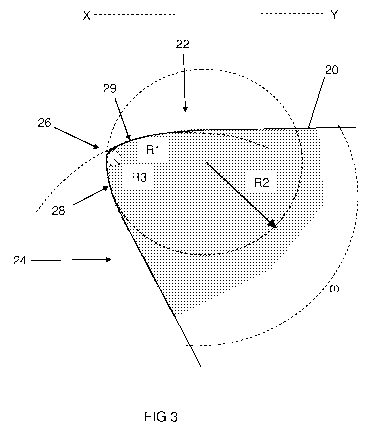
FIG 3 shows a schematic drawing of a partial side view (lateral projection)
cross section X-Y of the embodiment of a superhard insert shown in FIG 1
and FIG 2.
CA 02760600 2011-10-31
WO 2010/128085 PCT/EP2010/056120
6
FIG 4 shows a schematic drawing of a partial side view (lateral projection)
cross section through an embodiment of a superhard insert as in use
removing material from a workpiece.
FIG 5 shows a schematic partial cross sectional side view (lateral projection)
of an embodiment of a superhard insert.
The same reference numbers refer to the same respective features in all
drawings.
Detailed description of embodiments
As used herein, a "rake face" or "rake surface" of a cutting tool is the
surface
or surfaces of the cutting tool over which the chips flow in use. As used
herein, "chips" are the pieces of workpiece removed from the work surface by
a machine tool in use. When the rake face is composed of a number of
surfaces inclined to one another, these are designated first face, second
face,
and so forth, starting from the cutting edge.
As used herein, the "flank" is the tool surface or surfaces over which the
surface produced on the workpiece by the cutting tool passes (i.e. the surface
on the workpiece from which the chip material flowing over the rake face has
been cut). When the flank face is composed of a number of surfaces inclined
to one another, these are designated first flank, second flank, and so forth,
starting from the cutting edge. A clearance surface is sometimes referred to
in the art as a flank surface, and may also be composed of a first face,
second
face and so forth, starting from the cutting edge.
As used herein, the "cutting edge" is the edge of the rake face intended to
perform cutting. A "rounded cutting edge" is a cutting edge that is formed by
a
rounded transition between the rake face and the flank.
As used herein, a "superhard material" is a material having a Vickers
hardness of at least about 25GPa. Polycrystalline diamond (PCD) material
CA 02760600 2011-10-31
WO 2010/128085 PCT/EP2010/056120
7
and polycrystalline cubic boron nitride (PCBN) material are examples of
superhard materials. As used herein, POD material comprises a mass of
diamond grains, a substantial portion of which are directly inter-bonded with
each other and in which the content of diamond is at least about 80 volume %
of the material. In one embodiment of POD material, interstices among the
diamond gains may be at least partly filled with a binder material comprising
a
catalyst for diamond. As used herein, PCBN material comprises a mass of
cBN grains dispersed within a wear resistant matrix, which may comprise
ceramic or metal material, or both, and in which the content of cBN is at
least
about 50 volume % of the material. In some embodiments of PCBN material,
the content of cBN grains is at least about 60 volume %, at least about 70
volume % or at least about 80 volume %. As used herein, a "polycrystalline
superhard structure" means a structure comprising polycrystalline superhard
material.
As used herein, a "machine tool" is a powered mechanical device, which may
be used to manufacture components comprising materials such as metal,
composite materials, wood or polymers by machining. As used herein,
"machining" is the selective removal of material from a body, called a
workpiece.
With reference to FIG 1, FIG 2 and FIG 3, an embodiment of a superhard
insert 10 for a machine tool (not shown) for machining grooves into a metal
workpiece (not shown) comprises a polycrystalline diamond (PCD) structure
20 defining a rake face 22, a flank 24 and a rounded cutting edge 26 formed
by the transition between the rake face 22 and the flank 24, the rounded
cutting edge 26 having radius of curvature R3; the flank 24 comprising an
arcuate surface portion 28 extending from the cutting edge 26 and having a
radius of curvature R2 in a lateral projection. The arcuate surface portion 28
is generally convex when viewed in a lateral projection. The radius of
curvature R2 of the arcuate surface portion 28 of the flank 24 is greater than
the radius of curvature R3 of the rounded cutting edge 26, when viewed in a
lateral projection. The rake face 22 also comprises a convex arcuate surface
portion 29 extending from the rounded cutting edge 26 and having a radius of
CA 02760600 2011-10-31
WO 2010/128085 PCT/EP2010/056120
8
curvature R1 when viewed in a lateral projection. The arcuate surface portion
28 of the flank 24 may function as buttressing surface in use. The minimum
angle, co, enclosed between the rake face and the flank is at least about 66
degrees and less than 90 degrees.
As used herein, a rake angle is the inclination of a rake face relative to the
workpiece surface, a positive rake angle permitting chips to move away from
the workpiece and a negative rake angle directing chips towards the
workpiece.
With reference to FIG 4, the superhard cutting structure 20 of an embodiment
of an insert (full insert not shown) is disposed in use relative to a
workpiece 40
in a positive cutting geometry defined by a positive rake angle y and a
clearance angle a. The arcuate surface portion 28 of the flank, which may be
referred to as buttressing surface, may abut the workpiece 40 rearward of the
cutting edge 26 in relation to the rake face 22 and may project further
slightly
deeper into the body of the workpiece 40 than does the cutting edge 26.
Cutting may be achieved by driving the cutting structure 20 against the
workpiece 40 by, for example, causing it to rotate, or turn, in the direction
50
and cutting the workpiece 40, causing chips 60 to be removed by the cutting
action. In one embodiment, a is in the range from 1 degree to 12 degrees, y
is in the range from 0 degrees to 12 degrees, R1 is less than or equal to 10
millimetres, R2 is less than 10 millimetres, R3 is less than 0.15 millimetres,
and the angle co is between 66 degrees and 90 degrees.
With reference to FIG 5, an embodiment of a superhard insert 10 for a
machine tool (not shown) comprises a superhard structure 20 in the form of a
layer of PCD material bonded to a substrate 30 formed of cemented tungsten
carbide. The PCD structure 20 is formed with a rounded cutting edge 26 at
the transition between a rake face 22 and a flank 24, both the rake face 22
and the flank 24 comprising respective convex arcuate surface portions
adjacent the cutting edge 26. The cutting structure 20 is shown disposed as
CA 02760600 2011-10-31
WO 2010/128085 PCT/EP2010/056120
9
in use in a positive cutting geometry, defined by a positive rake angle y and
a
clearance angle a.
In use, the arcuate surface portion of the flank, or buttressing surface, may
abut the workpiece behind the cutting edge and projects somewhat deeper
into body of the workpiece than does the cutting edge. While wishing not to
be bound by a particular theory, the interior region of the insert adjacent
the
arcuate surface portion of the flank, or buttressing surface, may provide
increased mechanical support for the cutting edge in use, thereby functioning
to strengthen it.
Variations of the shape of the cutting structure may be used and adapted
depending on the characteristics of the workpiece, particularly the workpiece
material, and machining conditions, such as speed, depth of cut, feed rate
and so forth. For example, the flank or rake face, or both the flank and the
rake face may comprise more than one arcuate portion, or may comprise a
surface portion with a continuously varying radius of curvature. The structure
and properties of the superhard structure may also be adapted. For example,
in some embodiments the superhard structure may be formed of thermally
stable PCD, which may comprise a region from which catalyst for diamond
has been removed to enhance the properties of the POD at elevated
temperatures, or it may be formed of CVD diamond. At least a portion of the
rake or clearance surface, or both, may be coated with a coating for
protecting
the cutting structure or enhancing the machining operation. Such a coating
may comprise a material softer than that of the superhard structure, such as a
carbide, nitride or boride.
"Roughing" is understood to be an aggressive form of machining in which
workpiece material is removed at a relatively high rate by using a large depth
of cut and feed rate. This is distinguished from "finishing", where the
objective
being to produce a high tolerance finish, and so the depth of cut and feed
rates are lower. In roughing operations, the load on the cutting edge of a
tool
is far greater than in finishing operations and so the cutting edge needs to
be
CA 02760600 2011-10-31
WO 2010/128085 PCT/EP2010/056120
much stronger in a roughing operation, especially when the rake angle is
positive. This makes hard or super-hard, but relatively brittle materials
generally unsuitable for roughing certain difficult-to-machine workpiece
materials, such as titanium alloys. For example PCD, PCBN or advanced
ceramics are not typically used for the rough machining of difficult-to-
machine
materials, despite the high abrasion resistance of these materials.
Embodiments of the invention have the advantage that inserts comprising
cutting structures formed of superhard material have extended working life in
roughing or grooving of titanium-containing workpieces. While wishing not to
be bound by a particular theory, the arcuate surface portion of the flank may
function as a buttress, which may provide support for the cutting edge in use,
thereby delaying, preventing or reducing fracture at the cutting edge.
As used herein, the equivalent circle diameter (ECD) of a particle is the
diameter of a circle having the same area as a cross section through the
particle. The ECD size distribution and mean size of a plurality of particles
may be measured for individual, unbonded particles or for particles bonded
together within a body, by means of image analysis of a cross-section through
or a surface of the body.
Embodiments of the invention are described in more detail with reference to
the examples below, which are not intended to limit the invention.
Example 1
A polycrystalline diamond (PCD) compact was formed into an insert for a
cutting tool. The POD compact comprised a layer of POD integrally bonded to
cobalt-cemented tungsten carbide supporting substrate, the POD comprising
an inter-grown mass of diamond particles and cobalt dispersed within
interstices between the diamond particles. The diamond particles had a mean
size, in terms of equivalent circle diameter (ECD) in the range from about 0.5
micrometers to 2 micrometers and comprised at least 85% of the surface area
of any polished surface of the PCD. The transverse rupture strength of the
CA 02760600 2011-10-31
WO 2010/128085 PCT/EP2010/056120
11
POD was about 2,209 MPa, and its fracture toughness measured as K1 C, as
is well known in art, was about 13.4 MPa.m112. The POD had thermal
conductivity of about 166 W.m-'.K-1. The POD cutter insert was characterised
by the following geometrical parameters:
R1 = 1.5 mm (radius of curvature of the arcuate surface of the rake face)
R2 = 1.2 mm (radius of curvature of the arcuate surface of the flank)
R3 = 0.02 mm (radius of curvature of the rounded cutting edge)
co = 66 (wedge angle)
The cutting tool was subjected to test in which it was used to perform a
grooving operation on a workpiece formed of Ti-6AI-4V, using a Gildemeister
CTX410 machine tool. The cutting speed was 80 m/min, the feed rate was
0.2-0.3 mm/rev, the depth of cut was 3mm and the jet pressure was 150 bars.
The "end of life" criteria for the cutter were signs of chipping, fracture or
plastic
deformation, or a "Vbmax" wear scar length of 0.6mm. For comparison, a
carbide tool used commercially for this kind of application, as well as a POD
cutter of a known design were also subjected to the test. The tool life of the
POD cutting tool of the example exceeded 40 minutes, compared to about 9
minutes for the carbide tool and about 3 minutes for the known POD tool. The
known POD tool quickly failed as a result of fracture.
Example 2
A POD cutter insert was made as described in Example 1, except that the
POD cutter insert was characterised by the following geometrical parameters:
R1 = 9 mm (radius of curvature of the arcuate surface of the rake face)
R2 = 5 mm (radius of curvature of the arcuate surface of the flank)
R3 = 0.05 mm (radius of curvature of the rounded cutting edge)
co = 66 (wedge angle)