Note: Descriptions are shown in the official language in which they were submitted.
CA 02760838 2013-08-12
CA 2,760,838
Blakes Ref: 73518/00013
1 THERMALLY SWITCHED OPTICAL FILTER INCORPORATING A GUEST-HOST
2 ARCHITECTURE
3 CROSS REFERENCE TO RELATED APPLICATIONS
4 [0001] In addition, this application is related to U.S. patent
application publication no.
2009/0015902 entitled "Thermally switched reflective optical shutter" filed 11
July 2008; U.S.
6 patent application publication no. 2009/0167971 entitled "Thermally
switched absorptive window
7 shutter" filed 19 December 2008; U.S. patent application publication no.
2008/0210893 entitled
8 "Thermally switched optical downconverting filter" filed 24 January 2008;
U.S. patent application
9 publication no. 2009/0128893 entitled "Low emissivity window films and
coatings incorporating
nanoscale wire grids" filed 19 September 2008; U.S. patent application
publication no.
11 2009/0268273 entitled "Glare management of reflective and thermo
reflective surfaces" filed 23
12 April 2009, U.S. patent application publication no. 2010/0001008
entitled "Insulating glass unit
13 as shipping container" filed 2 July 2009; U.S. patent application
publication no. 2010/0045924
14 entitled "Methods for fabricating thermochromic filters" filed 20 August
2009; and U.S. patent
application publication no. 201 0/023201 7 entitled "Optical metapolarizer
device" filed 19 June
16 2009.
17 BACKGROUND
18 [0002] This technology relates to a device for controlling the flow
of light and radiant heat
19 through selective absorption or reflection of light. The technology has
particular, but not
exclusive, application in passive or active light-regulating and temperature-
regulating films,
21 materials, and devices, especially as a construction material.
22 [0003] Switchable mirrors exist which are based on reversible metal
hydride and metal
23 lithide chemistry described, for example, in U.S. Patent No. 7,042,615
to Richardson. These
24 switchable mirrors, which are chemically related to rechargeable
batteries, may rely on the
physical migration of ions across a barrier under the influence of an electric
field and, therefore,
26 have limited switching speeds and cycle lifetimes. In addition,
electrically operated "light valves"
27 that combine liquid crystals with one or more reflective polarizers are
described, for example, in
28 U.S. Patent No. 6,486,997 to Bruzzone et al. In these devices, a liquid
crystal typically serves as
29 an electrotropic depolarizer, i.e., a means of variably altering or
rotating the polarity of the light
1
22426730.2
CA 0 2 7 6 0 8 3 8 2 013- 0 8-12
CA 2,760,838
Blakes Ref: 73518/00013
1 that passes through it, under the influence of an electric field. Some of
these devices can be
2 thought of as switchable mirrors, although they are rarely described that
way, since their primary
3 application is in video displays, video projectors, and advanced optics.
4 [0004] Switchable electric light valves that do not require
polarizers, but are diffusive
forward scatterers or diffusive reflectors, also exist. This is because liquid
crystals themselves
6 may act as reflectors (including but not limited to distributed Bragg
reflectors or DBRs) with
7 different reflection bands in these applications, with a reflective,
diffusive, or forward-scattering
8 mode, and a more transmissive mode. These include the polymer-dispersed
liquid crystal
9 (PDLC) display, the cholesteric liquid crystal display (Ch-LCD), the
Heilmeier display, and the
Guest-Host display. The PDLC is an electrochromic device where the index of
refraction of
11 liquid crystal droplets embedded in another material is changed
electrically, resulting in more
12 scattering of the light in one mode than another. The Ch-LCD has two
stable states, the
13 reflective planar and focal conic texture. The reflective planar
structure reflects light if the Bragg
14 reflection condition is met and thus acts as a Bragg reflector for one
circular polarization of light,
while the reflective focal conic transmits more of the light.
16 [0005] An optical structure called a Guest-Host display commonly
utilizes dyes dispersed in
17 a liquid crystal, which absorb more light when in one orientation than
in another. The orientation
18 of the dyes is dependent on the orientation of the liquid crystal, which
is determined using an
19 electric field created by a voltage, typically applied via transparent
conducting layers such as
indium tin oxide. Such devices may also utilize one or more polarizers. There
are positive and
21 negative dichroic (pleochroic and negative dichroic) dyes, among others,
which respectively
22 absorb light along different axes of the molecule.
23 [0006] Polymer-stabilized liquid crystals are created when
prepolymers and liquid crystals
24 are mixed and the prepolymer is polymerized, to among other things
establish or reinforce the
orientation of the liquid crystals. Liquid crystal mixed with prepolymers
which are cured in
26 various ways and concentrations has been described in the literature,
among other terms, as
27 polymer-stabilized, polymer-networked, polymer-enhanced, and polymer-
dispersed, among
28 many other terms. This technology is well described in the prior art as,
for example, in U.S.
29 Patent No. 7,355,668 to Satyendra et al., which discloses polymer-
enhanced liquid crystal
devices, specifically electrically operated display devices, built with rigid
or flexible substrates
2
22426730.2
CA 0 2 7 6 0 8 3 8 2 013-0 8-12
CA 2,760,838
Blakes Ref: 7351 8/0001 3
1 that include polymer "columns" formed between substrate films through the
phase separation of
2 a prepolymer (e.g., Norland N0A77 or 78 optical adhesive) and a liquid
crystal (e.g., Merck E7,
3 E48, or E31 ), under the influence of temperature variations. The
prepolymer and liquid crystal
4 are mixed above the clearing point temperature of the LC, and are then
cooled below the
clearing point in order to separate, polymerize, and solidify the polymer
network within the liquid
6 crystal material.
7 [0007] More recently, in U.S. patent application publication no. US
2009/0015902 to Powers
8 et al., thermotropic liquid crystal shutters have been described, wherein
a thermotropic liquid
9 crystal is placed between two crossed polarizers, such that in one
temperature state the liquid
crystal forms a twisted nematic waveblock that rotates the polarity of
incoming light, allowing the
11 light transmission, absorption, and reflection properties of a single
polarizer, while in another
12 temperature state the liquid crystal is in an isotropic state, such that
it does not affect the
13 polarization state of incoming light. The device has the optical
properties of two crossed
14 polarizers, allowing much lower transmission and much higher absorption
or reflection of
incident light. The information included in this Background section of the
specification, including
16 any references cited herein and any description or discussion thereof,
is included for technical
17 reference purposes only and is not to be regarded as subject matter by
which the scope of the
18 invention is to be bound.
19 SUMMARY
[0008] The technology disclosed herein is directed to the temperature-based
control over
21 transmissivity, reflectivity, or absorptivity with regard to radiant
energy (e.g., visible, UV, and
22 infrared light), including up to the entire range of the solar spectrum,
for the purpose of
23 regulating the flow of heat into a structure (e.g., a window, building,
or vehicle) based on
24 external weather conditions, internal temperature, or any combination of
the two, responding
over a range of temperatures that make it useful for these purposes. This
technology is a device
26 having temperature-responsive transmission, absorption, or reflection of
light energy, effected
27 by temperature-induced changes in, among other things, the structure,
phase, or order of a
28 thermotropic carrier material (e.g., a thermotropic liquid crystal),
which provides temperature-
29 dependent order (or induces temperature-dependent order) to one or more
included
components that interact with light (e.g., reflective or absorptive dyes,
polymers, or inorganic
3
22426730.2
CA 0 2 7 6 0 8 3 8 2 013-0 8-12
CA 2,760,838
Blakes Ref: 73518/00013
1 markers), which, for purposes of this document, shall be referred to as
"orientation-dependent
2 colorants" (ODCs). Similar to usage with liquid crystal devices
generally, the particular local
3 spatial orientation characteristics of the thermotropic carrier material
at a given temperature
4 state shall be known as a "director." It should be understood that a
particular thermotropic
carrier material (e.g., a thermotropic liquid crystal), when used as a
component of an
6 embodiment described herein, may exhibit two or more discrete directors,
or an analog range of
7 directors, at different temperature states.
8 [0009] For example, at one temperature the thermotropic carrier
material may induce
9 significant order in one or more included ODCs (potentially including
absorptive, reflective, or
fluorescent molecules, dyes, particles, rods, polymer chains, or any
combination thereof)
11 suspended or dissolved within the thermotropic carrier material, while
at a second temperature
12 may provide little or no preferred director for these ODCs. If the
director associated with the first
13 temperature is chosen such that the included components interact less
with light at the first
14 temperature than the second temperature, the optical properties such as
transmission,
absorption, and fluorescence will be different at the two temperatures. The
efficiency of
16 absorption, reflection, or transmission can be varied through the
selection of the included ODC
17 materials, as can the frequency-dependent efficiencies. The choice of
ODC materials may be
18 used to affect percentages and wavelength ranges of reflection,
absorption, and transmission
19 above and below a threshold temperature, or over a selected range of
temperatures, that are
desirable for aesthetics, energy management, or other reasons.
21 [0010] Additionally, if the included ODC materials are reflective,
the device may be
22 diffusively reflective due to the distribution of orientations of the
included materials. This
23 technology has particular, but not exclusive, application as a glare
reduction method for building
24 surfaces. The efficiency, spatial distribution, bandwidth, and center
wavelength of reflection can
be varied as the orientation of the ODC changes under the influence of the
thermotropic carrier
26 material. Examples of reflective ODC materials include flakes, wires,
rods, particles, or
27 filaments. These may be composed of metals; of polymers or inorganic
ceramic-type materials
28 that are white or otherwise reflective in color; of polymers or
inorganic ceramic-type materials
29 that are transparent but which have refractive indices indexes
significantly mismatched to that of
the thermotropic carrier material; of polymer chains (e.g., polyacetylene)
that have inherent
4
22426730.2
CA 02 7 60 8 3 8 2 013-0 8-12
CA 2,760,838
Rakes Ref: 73518/00013
1 reflectivities due to an electrically conductive nature; or of related
materials or any combination
2 thereof.
3 [0011] This technology may also be employed as a part of a device
operating similarly in
4 function to a temperature-responsive optical depolarizer, (for example, a
thermotropic liquid
crystal) operating with one or more polarizing filters to regulate the passage
of light energy. The
6 order provided or induced in the included materials can be polarizing (in
transmission or
7 reflection) at one temperature, and less polarizing or even non-
polarizing in another. The
8 incident energies passing through this device will therefore depend on
the reflection and
9 absorption efficiencies of both the ODCs and of the polarizers used. For
example, when the
ODC is induced at one temperature to be a functionally efficient polarizer,
and paired with a
11 second efficient polarizer which transmits light of this same
polarization, then half of the incident
12 radiant energy passes through the device. However, if a temperature
change reduces the order
13 of the ODC such that the ODC will block transmission of light of both
polarizations, then the
14 amount of light transmitted through the device may therefore change as
well. Lower efficiency
polarizers, or ODCs and polarizers with frequency-dependent efficiencies, may
be selected to
16 affect percentages of reflection, absorption, and transmission above and
below a threshold
17 temperature or over a selected range of temperatures that are desirable
for aesthetics, energy
18 management, or other reasons. This effect can be such that the device is
less transmissive in
19 either its hot or cold state, or expanded such that the transmissivity
of the device is higher in the
transparent state. Angle-dependent optical effects may also exist.
21 [0012] The thermotropic carrier material may also induce different
amounts of order in one
22 or more included ODCs (whether absorptive, reflective, or fluorescent
molecules, dyes,
23 particles, rods, polymers, or any combination thereof) suspended or
dissolved within the carrier
24 material at different temperatures. For example, the thermotropic
carrier material, and any
associated alignment layers or structures, may be selected such that the
amount of order
26 provided may decrease with increasing temperatures. If the director
associated with the ODC is
27 chosen such that the included components interact more with light as the
temperature
28 increases, the optical properties such as transmission, absorption, and
fluorescence will
29 therefore vary as the temperature increases. Alternatively, among other
possibilities, the
director may be chosen such that the included ODCs interact more with light at
lower
31 temperatures than at higher temperatures, or the order provided may
increase with increasing
5
22426730.2
CA 02 7 60 8 3 8 2 013-0 8-12
CA 2,760,838
Blakes Ref: 73518/00013
1 temperature. Such devices are described, for example, in "Dichroic Dyes
for Liquid Crystal
2 Displays" (CRC Press, London, 1994) by Alexander V. lvashenko and "Liquid
Crystals" (Second
3 Edition 1992, Cambridge University Press, Cambridge, U.K.) by S.
Chandrasekhar. These
4 effects may also be combined with other effects, such as those previously
described, where
order is present at one temperature and not at a second, or where the order
changes
6 precipitously at a given temperature or across a temperature range, or
with other effects such
7 as having different orders for a given temperature based on the
temperature history (e.g.,
8 supercooling and hysteresis effects). The efficiency of absorption,
reflection, or transmission
9 response for different directors may be varied through the selection of
ODC materials, as can
the wavelength-dependent efficiencies. The choice of materials may be used to
affect
11 percentages and wavelengths of reflection, absorption, and transmission
above and below a
12 threshold temperature, or over a selected range of temperatures, that
are desirable for
13 aesthetics, energy management, or other reasons.
14 [0013] This technology may employ both specular and diffusive
optical effects as described
above, to create windows or window filters that exhibit both transparent and
opaque privacy-
16 type modes, and prevent the concentration of reflected solar energy in
UV, visible, or IR bands
17 in different ways. This technology may also be used to absorb, reflect
or transmit, diffusively or
18 specularly, various polarizations and wavelength ranges of light in
different ways at different
19 temperatures, to achieve particular aesthetic, privacy, glare, or solar
heat gain properties.
[0014] Other features, details, utilities, and advantages of the present
invention may be
21 apparent from the following more particular written description of
various embodiments of the
22 invention as further illustrated in the accompanying drawings and
defined in the appended
23 claims.
24 BRIEF DESCRIPTION OF THE DRAWINGS
[0015] Fig. 1 is a schematic view of an exemplary implementation of a
thermochromic filter
26 having ODC materials suspended or dissolved in a thermotropic carrier
material (e.g., a
27 thermotropic liquid crystal having moledules aligned perpendicular to
the substrate) that
28 provides or induces order for the ODC materials at a lower temperature
and does not at a
29 higher temperature.
6
22426730.2
CA 0 2 7 6 0 8 3 8 2 013-0 8-12
CA 2,760,838
Blakes Ref: 73518/00013
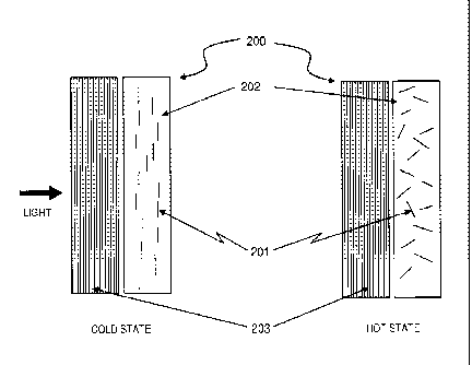
1 [0016] Fig. 2 is a schematic view of an exemplary implementation
of a thermochromic filter
2 used in combination with a polarizer. The thermochromic filter has ODC
materials suspended or
3 dissolved in a thermotropic carrier material (e.g., a thermotropic liquid
crystal having molecules
4 are aligned parallel to the substrate) that provides or induces order for
the ODC materials at a
lower temperature and does not at a higher temperature.
6 [0017] Fig. 3 is a schematic view of another exemplary
implentation of a thermochromic
7 filter having ODC materials suspended or dissolved in a thermotropic
carrier material e.g., a
8 vertically-aligned thermotropic liquid crystal) that provides or induces
more order in the ODC
9 materials at a lower temperature than it provides at a higher
temperature.
[0018] Fig. 4 is a schematic view of a further exemplary implementation of
a thermochromic
11 filter having ODC materials suspended or dissolved in a thermotropic
carrier material (e.g., a
12 vertically aligned thermotropic liquid crystal) where the directional
polarizing properties of one or
13 more thermotropic polarizer layers are used to vary the transmission
properties (including
14 polarizing effects) of the filter based on the direction of the light
being transmitted.
DETAILED DESCRIPTION
16 [0019] For the purposes of this specification, the term
"thermoreflective" shall refer to any
17 object, device, or material having a reflectivity that varies as a
function of temperature. Similarly,
18 "thermoabsorptive" and "thermoflourescent" shall refer to any objects,
devices, or materials
19 having an absoptivity or fluorescence, respectively, that varies as a
function of temperature.
Since light transmission is a function of reflection, absorption, and re-
radiation of light, any of
21 these objects, devices, or materials may also be properly described by
the more generic term,
22 "thermochromic".
23 [0020] Fig. 1 is a schematic, cross-section view of an exemplary
form of a thermochromic
24 filter device 100. The filter device 100 may be composed of included
"orientation dependent
colorant" or ODC materials 101 inside a transmissive, thermotropic, order-
providing carrier
26 material 102. At a lower temperature, assuming that the ODC molecules
interact more strongly
27 with incoming light perpendicular to their long axis, a significant
percentage of the incoming light
28 passes through the order-providing carrier material 102 as well as the
included ODC materials
29 101 due to their ordered orientation with respect to the incoming light.
As with a shutter or
7
22426730.2
CA 0 2 7 6 0 8 3 8 2 013-0 8-12
CA 2,760,838
Blakes Ref: 73518/00013
1 Venetian blind in the "open" state, the ODC materials are essentially
parallel to the incoming
2 light and thus do not substantially absorb or reflect it. At a higher
temperature, more of the
3 incoming light is blocked due to the unordered orientation of the
included ODC materials, a
4 large fraction of which are no longer parallel to the incoming light and
are therefore capable of
absorbing, reflecting, or otherwise interacting with it. It is notable that
when the included ODC
6 materials are in the ordered state, the filter device 100 is capable of
polarizing light that enters
7 the filter device 100 from directions other than the one indicated in the
figure, and thus may be
8 considered a "thermotropic polarizer" for some purposes.
9 [0021] Additional polarizers or other optical elements may also be
added to produce
different optical effects without affecting the essential nature thermochromic
filter device 100.
11 [0022] The thermotropic carrier material 102 may take a variety of
different forms for use
12 within the thermochromic filter device 100. Many materials that are
transparent to at least some
13 wavelengths of light also experience changes of the amount of order of
their molecules (or
14 changes in their director or directors) with changes in temperature. In
particular, many
thermotropic liquid crystals are optically transparent with high (almost
crystalline) order in the
16 liquid crystalline state (i.e., nematic state), while being optically
transparent with low order (e.g.,
17 a randomly or semi-randomly oriented state) in the isotropic state.
18 [0023] The director of liquid crystal molecules in a liquid crystal
state (such as the nematic
19 or smectic states) near a surface can be influenced through the use of
alignment layers. Both
vertical (homeotropic) and parallel (homogeneous) alignments are common, where
the director
21 of the liquid has respectively, a director normal or parallel to the
surface. The director can be
22 affected by the surface energy and chemistry of the surface. In general,
high surface energy
23 promotes parallel alignment and low surface energy promotes vertical
alignment. In the prior art,
24 polydimethylsiloxanes, for example, are commonly used to promote
vertical alignment and
rubbed polyimides, for example, are used to promote parallel alignments.
Methods for
26 promoting various alignments and pre-tilt angles, their intermediaries,
hybrids, combinations,
27 and the resulting useful structures when liquid crystal molecules are
placed near one, two, or
28 more surfaces are generally known, have been well described in the prior
art, and will be
29 familiar to a person of ordinary skill in the art. More complex
orientation states also exist and
8
22426730.2
CA 02 7 60 8 3 8 2 013- 0 8-12
CA 2,760,838
Blakes Ref: 73518/00013
1 have also been described. For example, in the liquid crystal "blue
phase," the director of the
2 liquid crystal molecule rotates in a helical fashion about any axis
perpendicular to a line.
3 [0024] If the thermotropic carrier material is a liquid crystal
(LC) material, it may be required
4 to meet environmental tolerance specifications that are consistent with
the environment in which
the device is to be used. For example, in an exemplary thermochromic window
application the
6 LC may require a clearing point between 20 C and 35 C, a freezing point
below -40^, a boiling
7 point above 90 C, and enough UV resistance to survive 30 years of daily
exposure to sunlight
8 (possibly attenuated by glass, polarizers, UV-blocking adhesives, and
other materials inherent
9 in the thermochromic window structure). Other requirements may also
exist, such as a
birefringence sufficient to produce the desired retardation across a
particular cell gap. In
11 particular it may be desirable for the device to have a small cell gap
in order to minimize the
12 amount of liquid crystal required. This would in turn imply a minimum
birefringence for the LC
13 mixture, in order to achieve the desired optical effects.
14 [0024] In general for LC mixtures, properties such as birefringence
and clearing point are
close to the weighted average of the individual components, whereas properties
like UV
16 resistance or chemical resistance may be limited by, or more strongly
dependent on, the
17 resistance of the least resistant component. Additionally, properties
such as freezing point
18 depend on the interactions of individual molecules, which become less
favorable for
19 crystallization as the molecules become more dissimilar from one
another. Thus, when two LC
components are mixed together, the resulting mixture may exhibit a freezing
point significantly
21 lower than either component by itself. Also, while the solubility of
different LC components
22 differs significantly depending on their molecular structure, the
solubility may be improved when
23 different components are present in the mixture, i.e., the solubility of
two mixed components in a
24 third component may be greater than the solubility of either component
separately.
[0026] For example, although 7CB liquid crystal has a freezing point of
approximately 30 C
26 and a clearing point of approximately 41 C, when mixed in equal
proportions with 5CB liquid
27 crystal, which has a freezing point of approximately 23 C and clearing
point of approximately 34
28 C, the LC mixture yielded has a clearing point of approximately 37 C
and a freezing point well
29 below -70 C. However, this mixture may be no more UV-stable than either
of its components,
and the chemical susceptibilities of both components still exist in the
mixture, as both molecules
9
22426730.2
CA 0 2 7 6 0 8 3 8 2 013-0 8-12
CA 2,760,838
Blakes Ref: 7351 8/0001 3
1 are capable of acting as organic solvents, especially at high
temperature, and may thus attack
2 certain organic substrate materials.
3 [0027] Mixtures of assorted LC components, which are combined to
produce particular
4 thermal, physical, chemical, and optical properties (including "eutectic"
mixtures), are generally
known. Perhaps the best known commercial LC mixture is E7, which is commonly
used in video
6 displays and is a mixture of 5 different LC components. The dominant
component is 5CB (which
7 has a low clearing point, good solubility, and small birefringence), but
the mixture also contains
8 significant quantities of 7CB, 80CB, 50CB, and 5CT (which has a high
clearing point, poor
9 solubility, and large birefringence). The mixture is designed to have a
broad nematic range, a
high clearing point, and a low freezing point, and the high solubility of the
5CB helps overcome
11 the low solubility of the 5CT. The principles and design rules of LC
mixtures such as these have
12 been well described in the art.
13 [0028] In the prior art, dye molecules have sometimes been
included in liquid crystals in
14 electrochromic devices as described, for example, in "Dichroic Dyes for
Liquid Crystal Displays"
(CRC Press, London, 1994) by Alexander V. lvashchenko. Such systems are often
called
16 Guest-Host systems and the devices called dichroic devices. With proper
selection of guest
17 components (i.e., ODCs) and host components (i.e., electrotropic carrier
materials), the dye
18 molecules assume (approximately) the director of the liquid crystal
molecule. Absorption and
19 other related optical effects often occur along an angle "near" the
director of the ODC molecule,
and can have a slight difference (e.g., 5-10 degrees) between the director and
maximum
21 absorption angle. There are positive (pleochroic) and negative dichroic
dyes which respectively
22 absorb light along different axes of the molecule. Therefore, some
embodiments disclosed
23 herein may be understood as resembling an electrochromic Guest-Host
system, except that the
24 carrier material has been designed such that it is thermotropic (as
described, for example, in
U.S. patent application publication no. 2009/0015902 to Powers et al. entitled
"Thermally
26 switched reflective optical shutter"), rather than electrotropic.
27 [0029] The orientation-dependent colorant (ODC) materials may also
take a number of
28 forms. For example, pleochroic dye systems generally have higher
dichroic ratios and order
29 parameters than negative dichroic dye systems. Embodiments may be
constructed that utilize
22426730.2
CA 02 7 60 8 3 8 2 013- 0 8-12
CA 2,760,838
Blakes Ref: 73518/00013
1 either positive or negative dichroic dyes, or a combination thereof, to
affect different
2 transmission properties across temperature ranges (e.g., shifting the
color balance or hue).
3 Performance of the dyes and system is affected by ultraviolet light (UV)
stability, solubility, and
4 order parameter of the dye(s) within the system. Performance of the
system is also affected by
liquid crystal host parameters, viscosity, order parameter, temperature range
of physical states,
6 stability, and birefringence. Note that Guest-Host systems for liquid
crystals and dichroic dyes
7 are often such that multiple dyes of one class are better at solvating,
i.e., a mixture of similar
8 dyes may have a greater total concentration than would be possible for
any of the component
9 dyes. Chemical "scaffolding" of dyes can also increase their solubility
(e.g., attaching a liquid
crystal molecule chemically to the dye molecule).
11 [0030] These various properties can be used to design a device with
desirab\transmission
12 properties. For example, if a particular dye has otherwise desirable
properties (e.g., high UV
13 stability) but low solubility in the desired Host, the thickness of the
Guest-Host system can be
14 increased to increase the attenuation of light transmitted. It should
also be understood that
many dyes that are unsuitable for electrochromic Guest-Host devices (e.g.,
cloth dyes) may be
16 suitable for thermotropic devices because device operation is not
contingent on electric fields.
17 [0031] Chiral (dopant) molecules may also be added to Guest-Host
systems to change or
18 improve the absorption or reflection of the guest(s). For example, a
nematic liquid crystal
19 system with multiple twists can be constructed using such molecules in
order to affect contrast
ratio or other optical properties. Optically active molecules can also be used
as guests in Guest-
21 Host systems, and can be used to construct systems that interact (e.g.,
reflectively) with circular
22 polarizations of light.
23 [0032] Semiconducting materials may also be used as guests to provide
infrared absorbing
24 and reflecting Guest-Host systems.
[0033] Side-chain liquid crystals, polymer nematic liquid crystals, and
nematic side-chain
26 polymers, and other such Host systems may have slower electrochromic
response times (or
27 have no electrochromic response) when used in electrochromic Guest-Host
devices, but they
28 may be particularly suitable for thermotropic systems. Dye copolymers
with liquid crystal may be
29 employed to improve effective solubility. Crystalline polymer liquid
crystal with embedded or
11
22426730.2
CA 02 7 60 8 3 8 2 013- 0 8-12
CA 2,760,838
Blakes Ref: 73518/00013
1 copolymer dyes may be employed to provide a transition of order without a
nematic or other
2 such state. Such a device would not function electrochromically, but may
be actuated by a
3 thermotropic carrier. Doped polyacetylene copolymers and/or side-chains
with liquid crystal are
4 also alternative embodiments of systems disclosed herein.
[0034] The order (or order parameter) of the Host system generally varies
with temperature
6 (as described, for example, in "Liquid Crystals Second Edition" by S.
Chandrasekar) and the
7 order (or order parameter) of the Guest or ODC varies with it. In
general, for classes of liquid
8 crystal Host chemistries or mixtures, as the clearing point increases, so
does the order
9 parameter of a particular Guest. Also, in general, as the clearing point
of the resulting system is
approached, the order parameter drops. These variations in order (or order
parameter) can be
11 continuous or discrete, or both, depending on the system and temperature
range. For example,
12 in Guest-Host nematic liquid crystal systems, the order parameter of the
host materials may be
13 reduced by increases in temperature until the clearing point, where the
liquid crystal then
14 becomes isotropic, and then the order of both the Guest and Host may be
effectively eliminated.
[0035] It should be understood that the director of the order in such
systems can be
16 determined using appropriate alignment materials and techniques.
Further, the amount of order
17 (order parameter) for a given Guest material (i.e., the included ODC
material) is a function of the
18 Host material chosen as well as the temperature, and that through
skillful materials selection
19 and system design, it is possible to achieve many different
relationships of temperature vs.
order. One desirable property in a temperature relation is to have the order
parameter of the
21 Guest vary monotonically with temperature over the temperature design
range of the device.
22 Another desirable property is to incorporate hysteresis into the
temperature relation. For
23 example, in a nematic, thermotropic liquid crystal Guest-Host device
utilizing the transition from
24 nematic to isotropic states, it may be desirable for aesthetic reasons
to have the "transition"
temperature be several degrees higher when the device is transitioning from
nematic to
26 isotropic than when transitioning from isotropic to nematic, as this
will reduce the probability that
27 the device will rapidly change transmission characteristics back and
forth when near the
28 transition temperature.
29 [0036] Polyacetylene is one polymer which can be modified chemically
to become highly
electrically conductive. This and other highly conductive polymers can
strongly interact with light
12
22426730,2
CA 02 7 60 8 3 8 2 013-0 8-12
CA 2,760,838
Blakes Ref: 73518/00013
1 reflectively, as in a wire-grid polarizer, and the interaction can be
dependent on the orientation
2 of the molecule. Conductive polymers can also interact with light
absorptively, with the
3 interaction dependent on the orientation of the molecule as well. Both
polymers and dye
4 molecules can be integrated into polymer stabilized twisted nematic
(PSTN) structures, as well
as other polymer/liquid crystal systems. By choosing the order parameter of
the doped
6 polyacetylene properly, it will be possible to select the ratio of
forward to backward scattering of
7 devices using conductive polyacetylene, as well as made with other
similar ODC Guests.
8 Polyacetylene molecules can also have chemical "scaffolding" molecules
attached to them to
9 increase their solubility.
[0037] Polyacetylene polymer can be manufactured into a reflective
polarizer by using it as
11 the Guest with polymer liquid crystal as the Host, and then cooling the
system until the the
12 polymers are fixed in place. Polyacetylene can also be manufactured into
reflective polarizers in
13 processes like those used to manufacture PVA-iodine polarizers.
14 [0038] The human eye responds to the relative amounts of several
ranges of visible light.
Thus many different spectral distributions may appear identical to the human
eye. Metamerism
16 is the matching of apparent color of objects with different spectral
power distributions, and
17 colors that match this way are called metamers. The absorption,
transmission, fluorescence,
18 and reflection of light by molecules (such as dye molecules) has a
spectral (frequency)
19 component to it. By properly selecting components (e.g., combinations of
dyes), it is possible to
select the perceived hue of transmission or reflection, or to select the
specific spectrum, or
21 amount of energy, that is transmitted or reflected, including UV,
visible, or IR light.
22 [0039] Numerous other combinations of thermotropic carrier ("host")
and orientation-
23 dependent colorant ("guest") materials are possible beyond those
discussed or enumerated
24 here and may be employed without departing from the spirit of this
embodiment.
[0040] Fig. 2 is a schematic, cross-section view of another exemplary
embodiment of a
26 thermochromic filter device 200. As in the prior embodiment of Fig. 1 ,
included ODC materials
27 201 are inside an order-providing thermotropic carrier material 202. A
polarizing film 203 is
28 placed between the incident light and the thermotropic carrier material
202 containing the
29 included ODC materials 201. However, assuming that the ODC molecules
interact more
13
22426730.2
CA 0 2 7 6 0 8 3 8 2 013-0 8-12
CA 2,760,838
Blakes Ref: 73518/00013
1 strongly with light along their long axis, the order provided is now such
that the included
2 materials 201 interact preferentially with one polarization of light. The
polarizer 203 also
3 interacts with this same polarization of light. Thus, in the lower
temperature state, if together the
4 "thermotropic polarizer" created by the ordered state of the included
materials 201 and the
polarizer 203 efficiently polarize the light, then approximately 50% of the
light is transmitted by
6 the device. In the higher temperature state, the "thermotropic polarizer"
created by the ordered
7 state of the included materials 201 no longer exists. The polarizer 203
still interacts with one
8 polarization of light, but now the included materials interact with both
polarizations of light,
9 reducing the amount of light transmitted to below 50%.
[0041] This arrangement may be advantageous for increasing the contrast
ratio of a Guest-
11 Host system, or for producing other desirable optical effects (e.g.,
particular combinations of
12 absorption and reflection at particular wavelengths) that would be
difficult to achieve with the
13 guest (ODC) and host (carrier) materials alone. The exact arrangement of
the layer may deviate
14 from the depiction in Fig. 2 without significantly affecting the
functioning of the device. Optically
speaking, it is of little consequence whether photons pass through the
polarizer and then the
16 guest-host system, or vice-versa. Various types of polarizers can be
used, including absorptive,
17 reflective, diffusive, and diffractive polarizers. In addition, more
than one polarizer may be
18 employed, and various optional components such as substrates, adhesives,
sealants, solubility
19 promoters, bandblock filters, longpass filters, shortpass filters, and
fixed tints may be added in
any combination without departing from the spirit of this embodiment.
21 [0042] However, it should be noted that if a retarder, waveblock,
or birefringence
22 compensation film or layer is employed, then the ordering of the layers
does matter. For
23 example, the polarization axis of a linear polarizing film is typically
parallel to the draw direction
24 of the film. However, if light passes through the polarizer and then a
waveblock layer, the
resulting polarized light can be "rotated" such that its polarization axis
occurs at 45 degrees (or
26 some other desirable angle) to the draw direction. This may be useful in
that in some cases a
27 45-degree polarization axis allows for a simpler manufacturing process,
as described in U.S.
28 Patent Application Publication No. 2010/0045924 by Powers et al.
Alternatively, compensating
29 to some angle slightly larger or smaller than 45 degrees may help to
"open up" the light
transmission of the filter by effectively misaligning the polarizers, such
that the contrast ratio of
14
22426730.2
=
CA 02 7 60 8 3 8 2 013-0 8-12
CA 2,760,838
Blakes Ref: 73518/00013
1 the device is reduced and the blocking-state light transmission is
increased, as described, for
2 example, in U.S. Patent Application Publication No. 2009/0015902 to
Powers et al.
3 [0043] It may be desirable in some circumstances to place
waveblocks on both polarizers in
4 a two-polarizer device, or on all polarizers in a multiple-polarizer
device. It may also be desirable
in other circumstances to place such optical films on only one polarizer. For
example, two
6 polarizers "rotated" by 45 degrees each may be comparable to one
polarizer "rotated" by 90
7 degrees and one polarizer not rotated at all. Reducing the number of
waveblocks may reduce
8 the cost of the final product while retaining the same functionality.
Therefore, it may be
9 recognized that waveblocks, retarders, birefringence compensation films,
birefringent materials
of particular thickness, or other related polarity-rotating materials or
devices may be combined
11 in a large variety of ways in various implementations of this
technology.
12 [0044] The amount of polarity rotation provided by a
retarder/waveblock or birefringence
13 compensation film or coating is proportional to both the birefringence
and the thickness of the
14 waveblock material. Thus, it is straightforward to devise a film or
coating to achieve very precise
amounts of polarity rotation, and the methods for doing so require no further
elaboration here,
16 except to note that achromatic waveplates will generally introduce fewer
color anomalies than
17 non-achromatic waveplates. The implementation also encompasses versions
where a standard
18 polarizer and thermotropic polarizer have perpendicular or otherwise non-
parallel polarization
19 axes, negative dichroics with parallel alignment, with and without an
ordinary (non-thermotropic)
polarizer, and versions wherein the device becomes more reflective,
absorptive, or fluorescent
21 when hot.
22 [0045] Fig. 3. is a schematic, cross-section view of another
exemplary embodiment of a
23 thermochromic filter device 300. As in the prior embodiments of Figs. 1
and 2, included ODC
24 materials 301 are inside an order-providing, thermotropic carrier
material 302. At a lower
temperature, a given percentage of the incoming light passes through the order-
providing
26 material 302 as well as the included materials 301 due to their ordered
orientation with respect
27 to the incoming light. At a higher temperature, the order of the
included materials is reduced (but
28 the order parameter is not zero), so that more of the incoming light is
absorbed or reflected due
29 to the unordered orientation of the included materials. Thus for this
device, the reduction in
transmitted light may be more gradual than for the embodiment of Fig. 1 . Note
that this device
22426730.2
CA 0 2 7 6 0 8 3 8 2 0 13¨ 0 8¨ 12
CA 2,760,838
Blakes Ref: 7351 8/0001 3
1 may polarize light coming from directions other than the one indicated in
the figure at both the
2 lower and higher temperatures, as the included ODC materials are in
ordered orientations at
3 both temperatures, and thus may be considered a "thermotropic polarizer"
for some purposes.
4 [0046] It should be understood that the structure and orientations
depicted in Fig. 3 may
exist as either the only possible states of the device, or as intermediate
states. For example, a
6 particular arrangement of ODC materials and thermotropic carrier
materials may produce the
7 orientations of Fig. 1 at extreme temperatures and the orientations of
Fig. 3 at more modest
8 temperatures, without departing from the spirit of either embodiment or
of this disclosure as a
9 whole.
[0047] Fig 4. is a schematic, cross-section view of an additional exemplary
embodiment of a
11 thermochromic filter device 400. As in the prior embodiments of Figs. 1
, 2, and 3, included ODC
12 materials 401 are inside an order-providing, thermotropic carrier
material 402. However, at a
13 lower temperature, a given percentage of the incoming light passes
through the order-providing
14 material 402 as well as the included ODC materials 401 due to their
ordered orientation with
respect to the incoming light. Further, at a higher temperature, the order of
the included ODC
16 materials 401 is reduced (but the order parameter is not zero), so that
more of the incoming light
17 is absorbed or reflected due to the unordered orientation of the
included ODC materials 401 .
18 Thus for this thermochromic filter device 400, the reduction in
transmitted light may be more
19 gradual than for the embodiment of Fig. 1. Again, this thermochromatic
filter device 400
polarizes light coming from directions other than the one indicated in Fig. 4
at both the lower
21 and higher temperatures. However, the director of the included ODC
materials 401 (determined
22 by the system) is chosen in accordance with desirable interactions of
the thermochromatic filter
23 device 400 with light that varies in incoming direction (e.g., such as
with solar energy, which
24 varies in incoming direction both due to rotation of the planet as well
as due to season).
[0048] The structure and orientations depicted in Fig. 4 may exist as
either the only possible
26 states of the device, or as intermediate states. For example, a
particular arrangement of ODC
27 materials and thermotropic carrier materials may produce the
orientations of Figure 1 at extreme
28 temperatures and the orientations of Fig. 4 at more modest temperatures,
without departing
29 from the spirit of either embodiment or of the present disclosure as a
whole.
16
22426730.2
CA 0 2 7 6 0 8 3 8 2 013- 0 8-12
CA 2,760,838
Blakes Ref: 73518/00013
1 [0049] The included ODC materials may be any number of materials
including dyes, rods,
2 particles, or polymers in a thermotropic (e.g., nematic) liquid crystal
carrier material. Properly
3 selected ODC guest materials will assume the order and director of the
liquid crystal while the
4 liquid crystal is in the nematic state (or other liquid crystalline
states such as smectic), and
somewhat or completely lose their order while the liquid crystal is in the
isotropic state. Then if
6 the liquid crystal is in a liquid crystalline state (e.g., nematic) and
aligned vertically between two
7 transparent parallel surfaces, light traveling through the device
perpendicular to the surfaces will
8 not significantly interact with the included ODCmaterial (e.g., positive
dichroic dyes). However,
9 as the temperature increases (i.e., above the isotropic temperature), the
thermotropic liquid
crystal will not have an aligned order. Thus, the liquid crystal will be more
randomly oriented and
11 will not impart order to the included materials, which will also be
randomly oriented and thus
12 interact significantly more with light traveling through the device
perpendicular to the surfaces.
13 Note again here, the guest material need not be a liquid crystal.
14 [0050] In a further implementation of this embodiment, the included
ODC material may be
an electrically conductive polymer. This selection is not made for electrical
reasons per se, but
16 for the desirable optical properties (absorption and reflection) that
are typical of electrically
17 conductive materials. Thus, the interactions with light may be selected
to be either reflective or
18 absorptive, or any combination thereof. In the randomly oriented state,
the reflections may not
19 be specular, but rather diffusively reflective, which is desirable in
many applications.
[0051] In some implementations of this embodiment, the included ODC
materials may be
21 inside a thermotropic carrier material (e.g., thermotropic liquid
crystal), which provides a director
22 parallel to the surfaces (i.e., is aligned in parallel) and thus light
traveling through the device
23 perpendicular to the surfaces will interact with the included ODC
material (e.g., positive dichroic
24 dyes) as a polarizer. One or more polarizers that are part of the device
may be oriented such
that they do not interact with the light that is transmitted through the
polarizer formed by the
26 included materials. However, as the temperature increases (i.e., rises
above isotropic
27 temperature), the material (e.g., a thermotropic liquid crystal) will
not have an aligned order, but
28 will be more randomly oriented, and thus will not impart order to the
included materials. Thus,
29 the included materials will also be randomly oriented and interact
significantly more with light of
the polarization transmitted by the polarizer(s), if any, and change how much
light is transmitted.
17
22426730.2
CA 02760838 2013-08-12
CA 2,760,838
Blakes Ref: 73518/00013
1 [0052] In other implementations, the included ODC materials
interact with light such that
2 when their director is perpendicular to the surfaces, the included
materials interact with the light
3 (e.g., absorb, reflect, or fluoresce the light) more strongly than when
their director is parallel to
4 the surfaces (i.e., negative dichroics).
[0053] While several exemplary embodiments are depicted and described
herein, it should
6 be understood that the present invention is not limited to these
particular configurations. For
7 example, the polarizers (if any) employed in the structure may be linear
or circular, absorptive or
8 reflective, diffusive or specular, and/or fixed or thermotropic in
nature. One or more polarizers
9 used in the device may be spectrally selective or may be selected to have
a high or low
polarizing efficiency. The order-providing materials can be thermotropic
liquid crystals,
11 ice/water, phase change materials, crystalline structures, or any of
many forms of matter which
12 can provide order to the included ODC materials. The polarizers,
including thermotropic
13 polarizers, may be in any relation to each other. The devices may be
configured to become
14 more transmissive with increases in temperature. Negative and positive
dichroic ODCs may
also be combined.
16 [0054] In addition, it should be understood that in some cases the
order and director may be
17 provided by the ODC material itself (e.g., crystalline materials), such
that the "guest" and "host"
18 functions are combined in a single, carefully selected or constructed
material. For example,
19 molecular chains of polyacetylene can act as electrical "wires" and may
be an excellent
candidate ODC "guest" material. However, polyacetylene chains also exhibit
liquid crystal
21 properties, and thus may be considered a "host" candidate as well, or a
component of the host.
22 [0055] Alternatively or in addition, the included ODC "guest"
materials and or the
23 thermotropic carrier or "host" materials may be attached to or
constrained by a polymer or
24 polymer network that is part of the substrate material, or may be
attached to one or more of the
substrate's surfaces.
26 [0056] In another variant of the above embodiments, the order of
the host material, and thus
27 of the included ODC material, may also be changed by an electrical
"override". An electrical
28 "override" may be present for the order-providing material, for example
by changing the order
29 and director of a nematic liquid crystal through the use of torquing
electrical fields. Alternatively,
18
22426730.2
CA 02760838 2013-08-12
CA 2,760,838
Blakes Ref: 73518/00013
1 the guest material may be the locus of the electrical "override" (e.g.,
as in a suspended particle
2 device). This may be particularly effective in cases where the ODC
"guest" or thermotropic
3 "host" consist of, or include, an electrically conductive polymer as
described above.
4 [0057] The included materials may be selected to provide desired
transmission, reflection,
fluorescence, and absorption characteristics, spectrums, hues, or aesthetics,
or to provide
6 desirable energy transmission, absorption, and reflection
characteristics. In addition, multiple
7 thermochromic devices, of either the same type or of different types, may
be combined to
8 produce different aesthetic, optical, thermal, privacy, visual contrast,
or solar heat gain
9 properties. The amount of order may locally or globally increase with
temperature rather than
decrease, or the device may be constructed such that the transmission of light
increases with
11 increasing temperature. The guest mixture may be monochrome or black,
tinted, fluorescent,
12 and/or metameric.
13 [0058] In another possible implementation, the device may
additionally be a thermotropic
14 polymer dispersed liquid crystal device. For this purpose, the Guest-
Host system may be
selected for low solubility in the polymer, or a low birefringence Host (e.g.
liquid crystal) may be
16 matched with the optical index of the polymer to improve device
performance and optical clarity.
17 [0059] It should also be understood that any or all of the
embodiments and variants
18 described above may be paired with a number of optional components
without altering their
19 essential nature or function. These may include, but are not limited to,
substrates, fixed tints,
adhesives, sealants, wave plates, reflectors, partial reflectors,
transreflectors, low-emissivity
21 materials, UV-absorptive or reflective materials, and/or IR absorptive
or reflective materials.
22 [0060] Additionally, there may be materials that provide more
order at higher temperatures,
23 or different amounts of order at different temperatures, such as the
change in order and director
24 with changes in temperatures that occurs in thermotropic liquid crystals
that have both nematic
and smetic states. Devices thus may be based on changes in the director or
order with
26 temperature rather than simply upon a loss of order with changes in
temperature. Additionally,
27 the included ODC material may in fact be simply in proximity to the
order providing carrier
28 material rather than wholly dissolved or suspended within it, or may
induce changes in the
29 amount of order the order-providing material provides at various
temperatures.
19
22426730.2
CA 02760838 2013-08-12
CA 2,760,838
Blakes Ref: 73518/00013
1 [0061] Optional components such as coatings, films, spacers,
fillers, or support structures
2 may be added to suit the needs of a particular application or a
particular manufacturing method,
3 and degraded forms of some embodiments can be produced by deleting or
substituting certain
4 components. The exact arrangement of the various layers can be different
than is depicted here
and, depending on the materials and wavelengths selected, different layers can
be combined as
6 single layers, objects, devices, or materials, without altering the
essential structure and function
7 of the invention.
8 [0062] Although the description above contains many specificities,
and reference to one or
9 more individual embodiments, these should not be construed as limiting
the scope of the
invention but rather construed as merely providing illustrations of certain
exemplary
11 embodiments of this invention. There are various possibilities for
implementation of different
12 materials and in different configurations and those skilled in the art
could make numerous
13 alterations to the disclosed embodiments without departing from the
spirit or scope of this
14 invention.
[0063] In addition, although various embodiments of this invention have
been described
16 above with a certain degree of particularity,all directional references
e.g., inside, proximal, distal,
17 upper, lower, inner, outer, upward, downward, left, right, lateral,
front, back, top, bottom, above,
18 below, vertical, horizontal, clockwise, counterclockwise, left circular,
and right circular are only
19 used for identification purposes to aid the reader's understanding of
the present invention, and
do not create limitations, particularly as to the position, orientation, or
use of the invention.
21 Connection references, e.g., attached, coupled, connected, and joined
are to be construed
22 broadly and may include intermediate members between a collection of
elements and relative
23 movement between elements unless otherwise indicated. As such,
connection references do
24 not necessarily imply that two elements are directly connected and in
fixed relation to each
other. Specific values cited in this texst, such as transition temperatures,
clearing points,
26 percentages of reflection, transmission or absorption are illustrative
and shall not be limiting.
27 More generally, it is intended that all matter contained in the above
description or shown in the
28 accompanying drawings shall be interpreted as illustrative only and not
limiting. Changes in
29 detail or structure may be made without departing from the basic
elements of the invention as
defined in the following claims.
22426730.2