Note: Descriptions are shown in the official language in which they were submitted.
CA 02761171 2013-11-08
PATTERNED HEAT MANAGEMENT MATERIAL
Technical Field
[0002] Embodiments of the present disclosure relate generally to a fabric
or
other material used for body gear and other goods having designed performance
characteristics, and in particular to methods and apparatuses that utilize a
pattern of
heat managing/directing elements coupled to a base fabric to manage heat
through
reflection or conductivity while maintaining the desired properties of the
base fabric.
Background
[0003] Currently, heat reflective materials such as aluminum and mylar
typically take the form of a unitary solid film that is glued or otherwise
attached to the
interior of a garment, such as a jacket. The purpose of this layer is to
inhibit thermal
radiation by reflecting the body heat of the wearer and thereby keeping the
garment
wearer warm in colder conditions. However, these heat reflective linings do
not
transfer moisture vapor or allow air passage, thus they trap moisture near the
body.
Because the application of a heat reflective material impedes the
breathability and
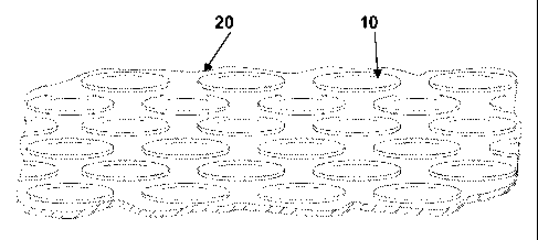
other functions of the underlying base fabric, use of heat reflective
materials during
physical activity causes the inside of a garment to become wet, thereby
causing
discomfort and accelerating heat loss due to the increased heat conductivity
inherent
in wet materials. Further, these heat reflective coated materials impair the
ability of
the material to stretch, drape, or hang in a desired fashion.
CA 02761171 2011-11-04
WO 2010/129923 PCT/US2010/034124
Brief Description of the Drawings
[0004] Embodiments of the present disclosure will be readily understood
by
the following detailed description in conjunction with the accompanying
drawings.
Embodiments of the invention are illustrated by way of example and not by way
of
limitation in the figures of the accompanying drawings.
[0005] Figures 1A illustrates an upper body garment such as a coat having
a
lining of base material with heat directing/management elements disposed
thereon,
in accordance with various embodiments;
[0006] Figures 1B ¨ 1E illustrate various views of examples of patterned
heat
directing/management elements disposed on a base fabric or material, in
accordance with various embodiments;
[0007] Figures 2A and 2B illustrate examples of patterned heat
directing/management elements disposed on a base fabric, in accordance with
various embodiments;
[0008] Figures 3A ¨ 3E illustrate examples of patterned heat
directing/management elements disposed on a base fabric, in accordance with
various embodiments;
[0009] Figure 4 illustrates an upper body garment such as a coat having a
lining of base material with heat directing/management elements disposed
thereon,
in accordance with various embodiments;
[0010] Figure 5 illustrates an upper body garment such as a coat having a
lining of base material with heat directing/management elements disposed
thereon,
in accordance with various embodiments;
[0011] Figure 6 illustrates an upper body garment such as a coat having a
lining of base material with heat directing/management elements disposed
thereon,
in accordance with various embodiments;
[0012] Figure 7 illustrates an upper body garment such as a coat having a
lining of base material with heat directing/management elements disposed
thereon,
in accordance with various embodiments;
[0013] Figures 8A-D illustrate various views of a patterned heat
management
material as used in a jacket, in accordance with various embodiments;
[0014] Figure 9 illustrates an example of a patterned heat management
material as used in a boot, in accordance with various embodiments;
2
CA 02761171 2011-11-04
WO 2010/129923 PCT/US2010/034124
[0015] Figure 10 illustrates an example of a patterned heat management
material as used in a glove, where the cuff is rolled outward to show the
lining, in
accordance with various embodiments;
[0016] Figure 11 illustrates an example of a patterned heat management
material as used in a hat, in accordance with various embodiments;
[0017] Figure 12 illustrates an example of a patterned heat management
material as used in a pair of pants, in accordance with various embodiments;
[0018] Figure 13 illustrates an example of a patterned heat management
material as used in a sock, in accordance with various embodiments;
[0019] Figure 14 illustrates an example of a patterned heat management
material as used in a boot, in accordance with various embodiments; and
[0020] Figures 15A and B illustrate two views of a patterned heat
management material as used in a reversible rain fly (Figure 15A) and as a
portion
of a tent body (Figure 15B), in accordance with various embodiments.
Detailed Description of Embodiments
[0021] In the following detailed description, reference is made to the
accompanying drawings which form a part hereof, and in which are shown by way
of
illustration embodiments in which the disclosure may be practiced. It is to be
understood that other embodiments may be utilized and structural or logical
changes
may be made without departing from the scope of the present disclosure.
Therefore,
the following detailed description is not to be taken in a limiting sense, and
the
scopes of embodiments, in accordance with the present disclosure, are defined
by
the appended claims and their equivalents.
[0022] Various operations may be described as multiple discrete
operations in
turn, in a manner that may be helpful in understanding embodiments of the
present
invention; however, the order of description should not be construed to imply
that
these operations are order dependent.
[0023] The description may use perspective-based descriptions such as
up/down, back/front, and top/bottom. Such descriptions are merely used to
facilitate
the discussion and are not intended to restrict the application of embodiments
of the
present invention.
[0024] The terms "coupled" and "connected," along with their derivatives,
may
be used. It should be understood that these terms are not intended as synonyms
for
3
CA 02761171 2011-11-04
WO 2010/129923 PCT/US2010/034124
each other. Rather, in particular embodiments, "connected" may be used to
indicate
that two or more elements are in direct physical or electrical contact with
each other.
"Coupled" may mean that two or more elements are in direct physical or
electrical
contact. However, "coupled" may also mean that two or more elements are not in
direct contact with each other, but yet still cooperate or interact with each
other.
[0025] For the purposes of the description, a phrase in the form "NB" or
in the
form "A and/or B" means (A), (B), or (A and B). For the purposes of the
description,
a phrase in the form "at least one of A, B, and C" means (A), (B), (C), (A and
B), (A
and C), (B and C), or (A, B and C). For the purposes of the description, a
phrase in
the form "(A)B" means (B) or (AB) that is, A is an optional element.
[0026] The description may use the phrases "in an embodiment," or "in
embodiments," which may each refer to one or more of the same or different
embodiments. Furthermore, the terms "comprising," "including," "having," and
the
like, as used with respect to embodiments of the present invention, are
synonymous.
[0027] In various embodiments a material for body gear is disclosed that
may
use a pattern of heat management material elements coupled to a base fabric to
manage, for example, body heat by directing the heat towards or away from the
body
as desired, while still maintaining the desired transfer properties of the
base fabric.
For example, referring to Figures 1B-1E, in one embodiment, a plurality of
heat
management or heat directing elements 10 may be disposed on a base fabric 20
in a
generally non-continuous array, whereby some of the base fabric is exposed
between adjacent heat management elements. The heat directing function of the
heat management elements may be generally towards the body through
reflectivity
or away from the body through conduction and/or radiation or other heat
transfer
property.
[0028] The heat management elements 10 may cover a sufficient surface
area
of the base fabric 20 to generate the desired degree of heat management (e.g.
heat
reflection toward the body to enhance warmth, or heat conductance away from
the
body to help induce cooling). A sufficient area of base fabric may be exposed
to
provide the desired base fabric function (e.g., stretch, drape, breathability,
moisture
vapor or air permeability, or wicking).
[0029] In accordance with various embodiments, the base fabric may be a
part of any form of body gear, such as bodywear (see e.g. Figures 1A and 4-
13),
sleeping bags (see e.g. Figure 14), blankets, tents (see e.g. Figure 15B),
rain flys
4
CA 02761171 2011-11-04
WO 2010/129923 PCT/US2010/034124
(see e.g. Figure 15A) etc. Bodywear, as used herein, is defined to include
anything
worn on the body, including, but not limited to, outerwear such as jackets,
pants,
scarves, shirts, hats, gloves, mittens, and the like, footwear such as shoes,
boots,
slippers, and the like, sleepwear, such as pajamas, nightgowns, and robes, and
undergarments such as underwear, thermal underwear, socks, hosiery, and the
like.
[0030] In various embodiments, single-layer body gear may be used and may
be comprised of a single layer of the base fabric, whereas other embodiments
may
use multiple layers of fabric, including one or more layers of the base
fabric, coupled
to one or more other layers. For instance, the base fabric may be used as a
fabric
lining for body gear.
[0031] In various embodiments, the array of heat management elements may
be disposed on a base fabric having one or more desired properties. For
example,
the underlying base material may have properties such as air permeability,
moisture
vapor transfer and/or wickability, which is a common need for body gear used
in both
indoor and outdoor applications. In other embodiments, the separations between
heat management elements help allow the base material to have a desired drape,
look, and/or texture. In some embodiments, the separations between heat
management elements help allow the base material to have a desired stretch.
Suitable base fabrics may include nylon, polyester, rayon, cotton, spandex,
wool,
silk, or a blend thereof, or any other material having a desired look, feel,
weight,
thickness, weave, texture, or other desired property. In various embodiments,
allowing a designated percentage of the base fabric to remain uncovered by the
heat
management material elements may allow that portion of the base fabric to
perform
the desired functions, while leaving enough heat management material element
surface area to direct body heat in a desired direction, for instance away
from or
toward the body of a user.
[0032] For example, the heat management elements may be positioned in
such a way and be made of a material that is conducive for directing heat
generated
by the body. In one embodiment, the heat management elements may be
configured to reflect the user's body heat toward the user's body, which may
be
particularly suitable in cold environments. In another embodiment, the heat
management elements may be configured to conduct the user's body heat away
from the user's body, which may be particularly suitable in warmer
environments.
CA 02761171 2011-11-04
WO 2010/129923 PCT/US2010/034124
[0033] In various embodiments, the base fabric may include heat
management elements disposed on an innermost surface of the body gear such
that
the elements are disposed to face the user's body and thus are in a position
to
manage body heat, as discussed above (e.g. reflect heat or conduct heat). In
some
other embodiments, the heat management elements may be disposed on the
exterior surface of the body gear and/or base fabric such that they are
exposed to
the environment, which may allow the heat management elements, for example, to
reflect heat away from the user, while allowing the base fabric to adequately
perform
the desired functions. In some embodiments, the heat management elements may
perform these functions without adversely affecting the stretch, drape, feel,
or other
properties of the base fabric.
[0034] In some embodiments, the heat management elements may be an
aluminum-based material (particularly suited for reflectivity), copper based
material
(particularly suited for conductivity), or another metal or metal alloy-based
material.
Non-metallic or alloy based materials may be used as heat directing materials
in
some embodiments, such as metallic plastic, mylar, or other man-made
materials,
provided that they have heat reflective or conductive properties.
[0035] In various embodiments, the heat management elements may be
permanently coupled to the base fabric in a variety of ways, including, but
not limited
to gluing, heat pressing, printing, or stitching. In some embodiments, the
heat
management elements may be coupled to the base fabric by frequency welding,
such as by radio or ultrasonic welding.
[0036] In various embodiments, the heat directing properties of the heat
management elements may be influenced by the composition of the base fabric or
the overall construction of the body gear. For example, a base fabric may be
used
that has significant insulating properties. When paired with heat management
elements that have heat reflective properties, the insulative backing/lining
may help
limit any conductivity that may naturally occur and enhance the reflective
properties
of the heat management elements. In another example, the base fabric may
provide
little or no insulative properties, but may be coupled to an insulating layer
disposed
on the side of the base fabric opposite the heat directing material elements.
The
separate insulation layer may help reduce the potential for heat conductivity
of the
elements and enhance their reflectivity. In some embodiments, the heat
management elements may become more conductive as the air layer between the
6
CA 02761171 2011-11-04
WO 2010/129923 PCT/US2010/034124
garment and the wearer becomes more warm and humid. Such examples may be
suitable for use in cold weather applications, for instance.
[0037] In various embodiments, a base fabric may be used that has little
or no
insulative properties. When paired with heat directing elements that are
primarily
configured to conduct heat, as opposed to reflecting heat, the base fabric and
heat-
directing elements may aid in removing excess body heat generated in warmer
climates or when engaging in extreme physical activity. Such embodiments may
be
suitable for warm weather conditions.
[0038] In various embodiments, the heat management material elements may
be applied in a pattern or a continuous or discontinuous array defined by the
manufacturer. For example, as illustrated in Figures 1A -1E, heat management
material elements 10, may be a series of dot-like heat reflective (or heat
conductive)
elements adhered or otherwise secured to the base fabric 20 in a desired
pattern.
Such a configuration has been found to provide heat reflectivity and thus
warmth to
the user (e.g., when heat reflective elements are used), or, in the
alternative, heat
conduction and thus cooling to the user (e.g., when heat conductive elements
are
used), while still allowing the base fabric to perform the function of the
desired one or
more properties (e.g. breathe and allow moisture vapor to escape through the
fabric
in order to reduce the level of moisture build up).
[0039] Although the illustrated embodiments show the heat management
material elements as discrete elements, in some embodiments, some or all of
the
heat management material elements may be arranged such that they are in
connection with one another, such as a lattice pattern or any other pattern
that
permits partial coverage of the base fabric.
[0040] In various embodiments, the configuration or pattern of the heat
management elements themselves may be selected by the user and may take any
one of a variety of forms. For example, as illustrated in Figures 2A-2B, 3A-
3E, and
4-6, the configuration of the heat management elements 10 disposed on a base
fabric 20 used for body gear may be in the form of a variety of geometrical
patterns
(e.g. lines, waves, triangles, squares, logos, words, etc.)
[0041] In various embodiments, the pattern of heat management elements
may be symmetric, ordered, random, and/or asymmetrical. Further, as discussed
below, the pattern of heat management elements may be disposed on the base
material at strategic locations to improve the performance of the body wear.
In
7
CA 02761171 2011-11-04
WO 2010/129923 PCT/US2010/034124
various embodiments, the size of the heat management elements may also be
varied to balance the need for enhanced heat directing properties and preserve
the
functionality of the base fabric.
[0042] In embodiments, the density or ratio of the surface area covered
by the
heat management material elements to the surface are of base fabric left
uncovered
by the heat management material elements may be from about 3:7 (30%) to about
7:3 (70%). This range has been shown to provide a good balance of heat
management properties (e.g., reflectivity or conductivity) with the desired
properties
of the base fabric (e.g., breathability or wicking, for instance). In
particular
embodiments, this ratio may be from about 4:6 (40%) to about 6:4 (60%).
[0043] In various embodiments, the placement, pattern, and/or coverage
ratio
of the heat management elements may vary. For example the heat management
elements may be concentrated in certain areas where heat management may be
more critical (e.g. the body core) and non existent or extremely limited in
other areas
where the function of the base fabric property is more critical (e.g. area
under the
arms or portions of the back for wicking moisture away from the body). In
various
embodiments, different areas of the body gear may have different coverage
ratios,
e.g. 70% at the chest and 30% at the limbs, in order to help optimize, for
example,
the need for warmth and breathability.
[0044] In various embodiments, the size of the heat management elements
may be largest (or the spacing between them may be the smallest) in the core
regions of the body for enhanced reflection or conduction in those areas, and
the
size of the heat management elements may be the smallest (or the spacing
between
them may be the largest) in peripheral areas of the body. In some embodiments,
the
degree of coverage by the heat management elements may vary in a gradual
fashion over the entire garments as needed for regional heat management. Some
embodiments may employ heat reflective elements in some areas and heat
conductive elements in other areas of the garment.
[0045] In various embodiments, the heat management elements may be
configured to help resist moisture buildup on the heat management elements
themselves and further enhance the function of the base fabric (e.g.
breathability or
moisture wicking). In one embodiment, it has been found that reducing the area
of
individual elements, but increasing the density may provide a better balance
between heat direction (e.g. reflectivity or conductivity) and base fabric
functionality,
8
CA 02761171 2011-11-04
WO 2010/129923 PCT/US2010/034124
as there will be a reduced tendency for moisture to build up on the heat
management
elements. In some embodiments, it has been found that keeping the surface area
of
the individual heat management elements below 1 cm2 can help to reduce the
potential for moisture build up. In various embodiments, the heat management
elements may have a maximum dimension (diameter, hypotenuse, length, width,
etc.) that is less than or equal to about 1 cm. In some embodiments, the
maximum
dimension may be between 1-4 mm. In other embodiments, the largest dimension
of
a heat management element may be as small as 1 mm, or even smaller.
[0046] In some embodiments, the topographic profile of the individual
heat
management elements can be such that moisture is not inclined to adhere to the
heat management element. For example, the heat management element may be
convex, conical, fluted, or otherwise protruded, which may help urge moisture
to flow
towards the base fabric. In some embodiments, the surface of the heat
management elements may be treated with a compound that may help resist the
build up of moisture vapor onto the elements and better direct the moisture to
the
base fabric without materially impacting the thermal directing property of the
elements. One such example treatment may be a hydrophobic fluorocarbon, which
may be applied to the elements via lamination, spray deposition, or in a
chemical
bath.
[0047] In various embodiments, the heat management elements may be
removable from the base fabric and reconfigurable if desired using a variety
of
releasable coupling fasteners such as zippers, snaps, buttons, hook and loop
type
fasteners (e.g. Velcro), and other detachable interfaces. Further, the base
material
may be formed as a separate item of body gear and used in conjunction with
other
body gear to improve thermal management of a user's body heat. For example, an
upper body under wear garment may be composed with heat management elements
in accordance with various embodiments. This under wear garment may be worn by
a user alone, in which case conduction of body heat away from the user's body
may
typically occur, or in conjunction with an insulated outer garment which may
enhance
the heat reflectivity of the user's body heat.
[0048] In various embodiments, the heat management elements may be
applied to the base fabric such that it is depressed, concave, or recessed
relative to
the base fabric, such that the surface of the heat management element is
disposed
below the surface of the base fabric. This configuration may have the effect
of
9
CA 02761171 2011-11-04
WO 2010/129923 PCT/US2010/034124
improving, for example, moisture wicking, as the base fabric is the portion of
the
body gear or body gear lining that engages the user's skin or underlying
clothing.
Further, such contact with the base fabric may also enhance the comfort to the
wearer of the body gear in applications where the skin is in direct contact
with the
base fabric (e.g. gloves, mittens, underwear, or socks).
[0049] Figures 8-15 illustrate various views of a patterned heat
management
fabric used in a variety of body gear applications, such as a jacket (Figures
8A-D),
boot (Figure 9), glove (Figure 10), hat (Figure 11), pants (Figure 12), sock
(Figure
13), sleeping bag (Figure 14), tent rain fly (Figure 15A) and tent (Figure
15B).
Each of the body gear pieces illustrated include a base material 20 having a
plurality
of heat management elements 10 disposed thereon.
[0050] While the principle embodiments described herein include heat
management elements that are disposed on the inner surface of the base fabric,
in
various embodiments, the heat management material elements may be used on the
outside of body gear, for instance to reflect or direct heat exposed to the
outside
surface of the gear. For instance, in some embodiments, base fabric and heat
reflective elements, such as those illustrated in Figures 1B-3E, may be
applied to an
outer or exterior surface of the body gear, such as a coat, sleeping bag, tent
or tent
rain fly, etc in order to reflect heat away from the user.
[0051] In some embodiments, the body gear may be reversible, such that a
user may determine whether to use the fabric to direct heat toward the body or
away
from the body. An example of such reversible body gear is illustrated in
Figure 15A.
In this embodiment, the heat management elements may be included on one side
of
a tent rain fly. In one embodiment, the rain fly may be used with the heat
management elements facing outward, for example in hot weather or sunny
conditions, in order to reflect heat away from the body of the tent user.
Conversely,
in cold weather conditions, for example, the tent rain fly may be reversed and
installed with the heat management elements facing inward, toward the body of
a
user, so as to reflect body heat back toward the tent interior. Although a
tent rain fly
is used to illustrate this principle, one of skill in the art will appreciate
that the same
concept may be applied to other body gear, such as reversible jackets, coats,
hats,
and the like. Figure 15B illustrates an example wherein at least a portion of
the tent
body includes a fabric having a plurality of heat management elements disposed
thereon. In the illustrated embodiment, the heat reflective elements are
facing
CA 02761171 2011-11-04
WO 2010/129923 PCT/US2010/034124
outward and may be configured to reflect heat away from the tent and thus away
from the body of the tent user. In other embodiments, the elements may be
configured to face inward.
[0052] Although certain embodiments have been illustrated and described
herein, it will be appreciated by those of ordinary skill in the art that a
wide variety of
alternate and/or equivalent embodiments or implementations calculated to
achieve
the same purposes may be substituted for the embodiments shown and described
without departing from the scope of the present invention. Those with skill in
the art
will readily appreciate that embodiments in accordance with the present
invention
may be implemented in a very wide variety of ways. This application is
intended to
cover any adaptations or variations of the embodiments discussed herein.
Therefore, it is manifestly intended that embodiments in accordance with the
present
invention be limited only by the claims and the equivalents thereof.
11