Language selection

Search

Patent 2761208 Summary

Third-party information liability

Some of the information on this Web page has been provided by external sources. The Government of Canada is not responsible for the accuracy, reliability or currency of the information supplied by external sources. Users wishing to rely upon this information should consult directly with the source of the information. Content provided by external sources is not subject to official languages, privacy and accessibility requirements.

Claims and Abstract availability

Any discrepancies in the text and image of the Claims and Abstract are due to differing posting times. Text of the Claims and Abstract are posted:

  • At the time the application is open to public inspection;
  • At the time of issue of the patent (grant).
(12) Patent: (11) CA 2761208
(54) English Title: BLADE DISK ARRANGEMENT FOR BLADE FREQUENCY TUNING
(54) French Title: LAME CIRCULAIRE POUR DISPOSITIF DE REGLAGE DE LA FREQUENCE D'OSCILLATION DES PALES
Status: Deemed expired
Bibliographic Data
(51) International Patent Classification (IPC):
  • F01D 5/10 (2006.01)
  • F01D 5/16 (2006.01)
  • F01D 5/26 (2006.01)
  • F16F 15/10 (2006.01)
(72) Inventors :
  • ABATE, ALDO (Canada)
  • KULATHU, RAM (Canada)
(73) Owners :
  • PRATT & WHITNEY CANADA CORP. (Canada)
(71) Applicants :
  • PRATT & WHITNEY CANADA CORP. (Canada)
(74) Agent: NORTON ROSE FULBRIGHT CANADA LLP/S.E.N.C.R.L., S.R.L.
(74) Associate agent:
(45) Issued: 2019-03-05
(22) Filed Date: 2011-12-07
(41) Open to Public Inspection: 2012-06-08
Examination requested: 2016-11-07
Availability of licence: N/A
(25) Language of filing: English

Patent Cooperation Treaty (PCT): No

(30) Application Priority Data:
Application No. Country/Territory Date
61/420,927 United States of America 2010-12-08

Abstracts

English Abstract

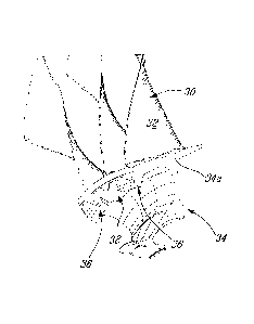
A gas turbine engine and a method of tuning a rotor in the gas turbine engine wherein the rotor includes an array of blades extending from a rotor hub each having an airfoil mounted to a blade platform. The method includes adding or removing material from bladed rotor projections to alter the mass of the rotor and change the frequency of the respective airfoil.


French Abstract

Un moteur à turbine à gaz et un procédé de réglage dun rotor dans le moteur à turbine à gaz, le rotor comprenant un ensemble de pales sétendant à partir dun moyeu de rotor ayant chacun un profil aérodynamique monté sur une plateforme de pale. Le procédé comprend lajout ou le retrait dune quantité de matière des saillies du rotor à pales pour modifier la masse du rotor et la fréquence du profil aérodynamique respectif.

Claims

Note: Claims are shown in the official language in which they were submitted.


CLAIMS:

1. A bladed rotor for a gas turbine engine, the bladed rotor comprising a
hub and a
circumferential array of blades extending from the hub; each blade having an
airfoil extending
from a gaspath side of a platform provided at a periphery of the hub: and an
annular array of
projections depending from an interior side of the blade platform at
circumferential locations
generally corresponding to every second blade, the projections cooperating to
form a
circumferentially interrupted rib, the interrupted rib configured to provide a
desired frequency
response to the bladed rotor.
2. The bladed rotor defined in claim 1, wherein the projections extend
radially inwardly
from the interior side of the platform.
3. The bladed rotor defined in claim 2, wherein the projections are located
at a leading edge
of the platform.
4. The bladed rotor defined in claim 2, wherein the projections are located
at a trailing edge
of the rotor.
5. The bladed rotor defined in claim 1, wherein the projections are
substantially identical in
terms of shape and mass.
6. The bladed rotor defined in claim 1, wherein the bladed rotor is an
integrally bladed
rotor, the projections being integral to the blade platform.
7. A method of tuning a bladed rotor in a gas turbine engine, wherein the
bladed rotor
includes a circumferential array of blades extending from a rotor hub, each
blade having an
airfoil extending from a blade platform; the method comprising: providing a
platform projection
depending from every second blade, the platform projections together forming a

circumferentially interrupted rib on the hub, and tuning the bladed rotor by
adding or removing
mass from at least one platform projection to alter the natural frequency of
the rotor.

6


8. The method defined in claim 7, wherein the platform projections have
substantially
identical shape and mass in the as-provided condition.
9. The method defined in claim 7, wherein tuning comprises removing or
adding sufficient
mass to change the frequency of at least one airfoil relative to the frequency
of adjacent airfoils.
10. The method defined in claim 7, wherein tuning the bladed rotor
comprises mistuning at
least one blade so that adjacent blades have different natural frequencies.

7

Description

Note: Descriptions are shown in the official language in which they were submitted.


CA 02761208 2011-12-07

BLADE DISK ARRANGEMENT FOR BLADE FREQUENCY TUNING
TECHNICAL FIELD

The present application relates to gas turbine engines and more particularly
to
improvements in a method and an arrangement for tuning/detuning a rotor blade
array.

BACKGROUND ART

Gas turbine rotor assemblies rotate at extreme speeds. Inadvertent excitation
of
resonant frequencies by the spinning rotor can cause an unwanted dynamic
response
in the engine, and hence it is desirable to be able to tune, or mistune, the
rotor in order
to avoid specific frequencies or to lessen their effect.

SUMMARY
In accordance with an general aspect, there is provided a method of tuning a
bladed
rotor in a gas turbine engine, wherein the bladed rotor includes a
circumferential array
of blades extending from a rotor hub, each blade having an airfoil extending
from a
blade platform; the method comprising: providing a platform projection
depending
from every second blade, the platform projections together forming a
circumferentially interrupted rib on the hub, and tuning the bladed rotor by
adding or
removing mass from at least one platform projection to alter the natural
frequency of
the rotor.

In accordance with another aspect, there is provided a bladed rotor for a gas
turbine
engine, the bladed rotor comprising a hub and a circumferential array of
blades
extending from the hub; each blade having an airfoil extending from a gaspath
side of
a platform provided at a periphery of the hub; and an annular array of
projections
depending from an interior side of the blade platform at circumferential
locations
generally corresponding to every second blade, the projections cooperating to
form a
1


CA 02761208 2011-12-07

circumferentially interrupted rib, the interrupted rib configured to provide a
desired
frequency response to the bladed rotor.

In accordance with a further general aspect, there is provided a method of
tuning a
bladed rotor for a gas turbine engine, the bladed rotor including a rotor hub
having a
circumferential array of airfoil blades extending therefrom, the hub having a
gas path
side defining a portion of the gas path in which the bladed assembly is to be
mounted
and an interior side opposite the gas path side; the method comprising:
providing at
least one projection extending from the rotor hub interior side, determining a
frequency response of the bladed assembly in an as-manufactured condition,
determining a desired frequency response, and then modifying the at least one
projection to provide the bladed assembly with the desired frequency response.
BRIEF DESCRIPTION OF THE DRAWINGS

Reference is now made to the accompanying figures in which:

Fig. 1 is a schematic cross-sectional view of a gas turbine engine
illustrating a
turbofan configuration;

Fig. 2 is an isometric view partly fragmented showing a rib feature of a rotor
blade
that may be used for blade tuning; and

Fig. 3 is an isometric view of a portion of a bladed rotor illustrating an
alternate rib-
no- rib configuration for mistuning blade frequencies.

DESCRIPTION OF THE PREFERRED EMBODIMENTS

Fig. 1 schematically depicts a turbofan engine A which, as an example,
illustrates the
application of the described subject matter. The turbofan engine A includes a
nacelle
10, a low pressure spool assembly which includes at least a fan 12 and a low
pressure
turbine 14 connected by a low pressure shaft 16, and a high pressure spool
which

includes a high pressure compressor 18 and a high pressure turbine 20
connected by a
high pressure shaft 22. The engine A further comprises a combustor 26.

2


CA 02761208 2011-12-07

The fan 12, the high pressure compressor 18, the high pressure turbine 20 and
the low
pressure turbine 14, for the purposes of the present description include
rotors
represented by the blades 30 in figure 1.

The rotors, especially the fan 12, may be provided in the form of blisks, that
is, in the
form of integrally bladed disks (IBR). As shown in Fig. 2, the blades 30 are
integrally
formed with a rotor hub 34 in a unitary construction. Each blade 30 comprises
an
airfoil 32 extending from a gas path side of an annular platform 34a formed at
the
periphery of the rotor hub 34. In use, the airfoils 32 may vibrate at
different
frequencies and in order to tune the rotor, the individual airfoils 32 must be
tuned or
mistuned. For instance, where adjacent airfoils have the same natural
frequencies, the
airfoils can excite each other. Thus, the airfoils may be mistuned to avoid
the
excitation.

As shown in Figs. 2 and 3, a series of projections 36 may be provided below
the
platform 34a or on the interior side of the platform 34a opposite to the gas
path side
thereof. The projections 36 may be integrally formed with the platform 34a.
The
projections 36a may be provided in the form of rib features depending radially
inwardly from the platform 34a. The projections 36 may be identical in term of
shapes
and sizes. The projections 36 may also be circumferentially spaced-apart in
annular
alignment forming a regular rib but which is interrupted by voids or spaces
38. In the
embodiment shown in Fig. 3, a projection 36 is provided at alternate or on
every
second blade 30 and, therefore, at every second airfoil for the purpose of
tuning or
mistuning the airfoil. However, it is understood that various number of
projections
may be provided. As shown in Figs. 2 and 3, the projections 36 may be provided
at
the leading edge of the platform 34a forwardly of the center of gravity of the
blades
30, but other suitable locations for the projection may be used (e.g. platform
trailing
edge).

If the airfoils 32 of two adjacent blades 30 have the same natural frequency,
one may
mistune the blade 30 to which a projection 36 is dependent so that the
frequency of
the respective airfoil 32 will be mismatched to the frequency of the airfoil
32 on the
adjacent blade 30.

3


CA 02761208 2011-12-07

The projections 36 may be tuned or mistuned by removing material therefrom
thereby
altering the mass thereof, causing the respective airfoil 32 to be modified in
terms of
its frequency. Alternately, material can be added to the projection 36 by a
bonding
process like welding. A projection 36 or similar rib features depending from
the blade
platform may be in this manner used to control blade frequencies.

The array of projections 36 are shown as being located at the leading edge of
the
platform 34a but it is understood that the array of projections 36 may be
located at the
trailing edge or other suitable location on the platform 34a. The shape of the
projections 36 making up the array may be identical forming a regular shaped
rib
albeit interrupted.

It can be appreciated that a gas turbine engine rotor may be tuned by
providing at least
one projection extending from a platform interior side, determining a
frequency
response of the bladed rotor in an as-manufactured condition, determining a
desired
frequency response, and then modifying the at least one projection to provide
the
bladed rotor with the desired frequency response. Modifying the at least one
projection may be done by removing material from the projection or by adding
material thereto.

The material addition (i.e. the projections 36) on the disk provides a
convenient way
of changing the blade frequencies. The projections 36 may be used to tune or
mistune
the blades (where frequencies of adjacent blades are different) to provide the
bladed
rotor with the desired frequency response.

The above description is meant to be exemplary only, and one skilled in the
art will
recognize that changes may be made to the embodiments described without
departing
from the scope of the invention disclosed. For instance, it will be understood
that he
present teaching may be applied to any bladed rotor assembly, including but
not
limited to fan and compressor rotors, and may likewise be applied to any
suitable
rotor configuration, such as integrally bladed rotors, conventional bladed
rotors etc.
Any modifications which fall within the scope of the present invention will be
4


CA 02761208 2011-12-07

apparent to those skilled in the art, in light of a review of this disclosure,
and such
modifications are intended to fall within the scope of the appended claims.


Representative Drawing
A single figure which represents the drawing illustrating the invention.
Administrative Status

For a clearer understanding of the status of the application/patent presented on this page, the site Disclaimer , as well as the definitions for Patent , Administrative Status , Maintenance Fee  and Payment History  should be consulted.

Administrative Status

Title Date
Forecasted Issue Date 2019-03-05
(22) Filed 2011-12-07
(41) Open to Public Inspection 2012-06-08
Examination Requested 2016-11-07
(45) Issued 2019-03-05
Deemed Expired 2019-12-09

Abandonment History

There is no abandonment history.

Payment History

Fee Type Anniversary Year Due Date Amount Paid Paid Date
Application Fee $400.00 2011-12-07
Maintenance Fee - Application - New Act 2 2013-12-09 $100.00 2013-11-28
Maintenance Fee - Application - New Act 3 2014-12-08 $100.00 2014-10-07
Maintenance Fee - Application - New Act 4 2015-12-07 $100.00 2015-09-29
Request for Examination $800.00 2016-11-07
Maintenance Fee - Application - New Act 5 2016-12-07 $200.00 2016-11-22
Maintenance Fee - Application - New Act 6 2017-12-07 $200.00 2017-11-22
Maintenance Fee - Application - New Act 7 2018-12-07 $200.00 2018-11-27
Final Fee $300.00 2019-01-17
Owners on Record

Note: Records showing the ownership history in alphabetical order.

Current Owners on Record
PRATT & WHITNEY CANADA CORP.
Past Owners on Record
None
Past Owners that do not appear in the "Owners on Record" listing will appear in other documentation within the application.
Documents

To view selected files, please enter reCAPTCHA code :


To view images, click a link in the Document Description column. To download the documents, select one or more checkboxes in the first column and then click the "Download Selected in PDF format (Zip Archive)" or the "Download Selected as Single PDF" button.

List of published and non-published patent-specific documents on the CPD .

If you have any difficulty accessing content, you can call the Client Service Centre at 1-866-997-1936 or send them an e-mail at CIPO Client Service Centre.


Document
Description 
Date
(yyyy-mm-dd) 
Number of pages   Size of Image (KB) 
Abstract 2011-12-07 1 10
Description 2011-12-07 5 196
Claims 2011-12-07 2 69
Drawings 2011-12-07 2 34
Representative Drawing 2012-05-14 1 11
Cover Page 2012-06-04 1 39
Examiner Requisition 2017-09-25 3 190
Amendment 2018-03-14 4 128
Claims 2018-03-14 2 53
Final Fee 2019-01-17 2 76
Representative Drawing 2019-02-04 1 9
Cover Page 2019-02-04 1 35
Assignment 2011-12-07 4 173
Request for Examination 2016-11-07 2 70