Note: Descriptions are shown in the official language in which they were submitted.
CA 02761593 2011-11-09
t .
GNC10007CA
DESCRIPTION
HEXAGONAL CUBE CORNER RETROREFLECTIVE ARTICLE
Technical Field
[0001]
The present invention relates to a hexagonal cube corner
retroreflective article, and more particularly to a hexagonal
cube corner retroreflective article excellent in observation
angle characteristics that can be preferably used in a traffic
sign, a construction sign, a warning sign, a guide sign, a
vehicle marking, retroreflective clothing, a reflector for an
optical sensor, light gathering prism sheeting for use in a
liquid crystal display device, or the like.
Background Art
[0002]
Conventionally, some proposals are made
on
retroreflective articles formed of hexagonal cube corner
retroreflective elements having excellent retroreflective
efficiency and entrance angle characteristics. However, a few
techniques disclose what method is preferable for providing
excellent observation angle characteristics.
[0003]
For example, US Patent No. 1,591,572 (Patent Document 1)
by Stimson discloses hexagonal cube corner retroreflective
elements. However, there is no description as to what shapes
of elements provide excellent entrance angle characteristics,
1
CA 02761593 2011-11-09
GNC10007CA
observation angle characteristics, and rotation angle
characteristics.
[0004]
US Patent No. 3,417,959 (Patent Document 2) and US Patent
No. 3,922,065 (Patent Document 4) by Schultz disclose a method
(pin bundling method) of forming a prism at the tip of a metal
pin and bundling a number of such pins to form a prism
assembly. This method is suitable for producing relatively
large prisms, but is not practical when it is necessary to
form 2,000/cm2 or more microprisms, for example.
[0005]
US Patent No. 3,458,245 (Patent Document 3) by Stanley
discloses retroreflective prisms having an obtuse angle and an
acute angle alternately arranged in at least two faces, or
preferably four faces or more.
[0006]
US Patent No. 3,924,929 (Patent Document 5) by Holmen et
al. also describes a retroreflective article formed of a
repeated pattern of units in which hexagonal prisms are
hermetically sealed.
[0007]
US Patent No. 4,066,331 (Patent Document 6) by Lindner
also describes a retroreflective article in which different
hexagonal prisms are arranged in each row.
[0008]
US Patent No. 4,073,568 (Patent Document 7) by Heasley
also describes a retroreflective article in which one kind of
2
CA 02761593 2011-11-09
GNC10007CA
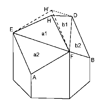
hexagonal prism is arranged in a repeated pattern.
[0009]
Similarly, US Patent No. 4,189,209 (Patent Document 8) by
Heasley also describes a retroreflective article in which two
kinds of hexagonal prisms having different thickness are
arranged in a repeated pattern.
[0010]
US Patent No. 6,114,009 (Patent Document 9) by Smith
describes a mold suitable for forming cube corner
retroreflective sheeting, a method for producing the mold, and
retroreflective sheeting formed using the mold, and
particularly discloses a mold formed of a plurality of thin
laminae and a method for producing the mold.
[0011]
Japanese Utility Model Application Laid-Open No. 63-
109233 (Patent Document 10) by Kato describes a reflective
article formed of a first reflecting part having reflective
performance with respect to an incident light beam at a
critical angle or larger from the left and a second reflecting
part having reflective performance with respect to an incident
light beam at a critical angle or larger from the right.
[0012]
US Patent No. 6,120,280 (Patent Document 11) and US
Patent No. 6,010,609 (Patent Document 12) by Mimura et al.
disclose a design of hexagonal cube corner retroreflective
elements having an asymmetrical shape in which optical axes
are tilted leftward and rightward of the elements and a method
3
CA 02761593 2011-11-09
GNC1 0007CA
of making the element.
[0013]
It is described therein that entrance angle
=
characteristics are improved in two directions, in which the
optical axes are tilted, according to such hexagonal cube
corner retroreflective elements having the optical axes tilted
to the right and left of the elements. However, in the
elements disclosed in these patent documents, excellent
improvement cannot be achieved in rotation angle
characteristics.
[0014]
On the other hand, US Patent No. 6,318,866 (Patent
Document 13) by Mimura et al. discloses various proposals on
improvement of observation angles.
[0015]
Patent Document 13 discloses that observation angle
characteristics can be improved by forming opposite lateral
faces of a pair of triangular pyramidal cube corner
retroreflective elements in different shapes.
[0016]
US Patent No. 4,775,219 (Patent Document 14) by Appeldorn
et al. discloses a method of improving the observation angle
characteristics of a retroreflective article formed of a group
of triangular pyramidal retroreflective elements.
[0017]
The method of improving the observation angle disclosed
in Patent Document 14 is that the angle of a V-shaped groove
4
CA 02761593 2011-11-09
GNC1 0007CA
forming the element in three directions is changed in
repeating patterns in lateral asymmetry at an angle different
from the angle of the adjacent V-shaped groove, whereby
forming triangular pyramidal retroreflective elements with
various prism apexes.
Citation List
Patent Documents
[0018]
Patent Document 1: US Patent No. 1,591,572
Patent Document 2: US Patent No. 3,417,959
Patent Document 3: US Patent No. 3,458,245
Patent Document 4: US Patent No. 3,922,065
Patent Document 5: US Patent No. 3,924,929
Patent Document 6: US Patent No. 4,066,331
Patent Document 7: US Patent No. 4,073,568
Patent Document 8: US Patent No. 4,189,209
Patent Document 9: US Patent No. 6,114,009
Patent Document 10: Japanese Utility Model Application Laid-
Open No. 63-109233
Patent Document 11: US Patent No. 6,120,280
Patent Document 12: US Patent No. 6,010,609
Patent Document 13: US Patent No. 6,318,866
Patent Document 14: US Patent No. 4,775,219
Summary of Invention
Objects to be Achieved by the Invention
CA 02761593 2013-09-23
53511-11
[0019]
As described above, although there are known some
retroreflective articles with improved observation angle
characteristics, retroreflective articles with more improved
observation angle characteristics are demanded. Therefore, it
is an object of the present invention to provide a
retroreflective article using a hexagonal cube corner
retroreflective element with excellent observation angle
characteristics that can be preferably for use in a traffic
sign or the like.
Summary of the Invention
[0021]
Conventionally publicly known techniques and a hexagonal
cube corner retroreflective element according to the present
invention refer to a cube corner retroreflective element,
which is a reflector element in which three quadrilateral
reflective lateral faces share one apex and three edge lines
and outer circumferential edges define hexagonal projection
geometry. This hexagonal cube corner retroreflective element
is significantly excellent in retroreflective efficiency more
than a triangular pyramidal cube corner retroreflective
element preferably for use in a traffic sign or the like.
[0022]
6
CA 02761593 2011-11-09
GNC10007CA
Three reflective lateral faces constituting the hexagonal
cube corner retroreflective element according to the present
invention are vertical to each other, forming so-called cube
corner faces. However, since observation angle characteristics
are improved by slightly widening a pencil of retroreflected
light, preferably, a slight angle deviation is provided for
faces vertical to each other to form a retroreflective element
with so-called vertical angle deviation.
[0023]
In triangular pyramidal cube corner retroreflective
elements, various schemes are proposed for improving
observation angle characteristics by providing such vertical
angle deviation. However, in hexagonal cube corner
retroreflective elements, there are no proposals what method
provides preferable observation angle characteristics.
[0024]
It is noted that the common plane of a retroreflective
article according to the present invention refers to a virtual
plane in parallel with a plane shared by apexes of a group of
reflector elements in the same shape. Generally, the common
plane can be considered to be a face matched with the
incidence plane of the retroreflective article.
[0025]
The optical axis in the present invention is defined as
an optical center axis located at an equal distance from three
reflective lateral faces. In the case where an external light
beam enters the hexagonal cube corner retroreflective element
7
CA 02761593 2011-11-09
GNC1 0007CA
in parallel with the optical axis, the hexagonal cube corner
retroreflective element can obtain excellent retroreflective
efficiency, whereas in the case where an external light beam
enters the hexagonal cube corner retroreflective element at an
angle off the optical axis, retroreflective efficiency is
reduced in proportion to that angle. Thus, if the optical axis
is tilted in the direction of the incident light beam
beforehand, it is possible to improve retroreflective
efficiency in the direction in which the optical axis is
tilted.
[0026]
In the hexagonal cube corner retroreflective element
according to the present invention, three quadrilateral
reflective lateral faces (face a, face b, and face c) share
three edge lines (HD, HE, and HF) and one apex (H) with each
other, and the lateral faces are defined by six outer
circumferential edges (AE, EC, CD, DE, BF, and FA). The
hexagonal cube corner retroreflective element according to the
present invention has an optical axis passing through the apex
(H) of the retroreflective element and located at an equal
distance from these three reflective lateral faces (face a,
face b, and face c).
[0027]
In the hexagonal cube corner retroreflective element
according to the present invention, at least one reflective
lateral face (face a, face b, and/or, face c) partitioned by a
line segment (EF, FD, and/or DE) connected by apexes (E, F,
8
CA 02761593 2013-09-23
53511-11
and/or D) constituting that reflective lateral face. As a
result, the hexagonal cube corner retroreflective element
according to the present invention is formed of six secondary
reflective lateral faces, at the maximum, the six secondary
reflective lateral faces each being divided into a pair of an
upper secondary reflective lateral face (face al, face bl,
and/or face cl) and a lower secondary reflective lateral face
(face a2, face b2, and/or face c2). It is noted that although
all the reflective lateral faces are not necessarily divided
into the upper secondary reflective lateral face and the lower
secondary reflective lateral face, preferably, three
reflective lateral faces are all divided into six secondary
reflective lateral faces, in order to obtain uniform
observation angle characteristics in all the orientations. In
the hexagonal cube corner retroreflective element according to
the present invention, two secondary reflective lateral faces
(the upper secondary reflective lateral face and the lower
secondary reflective lateral face), which constitute a pair of
these secondary reflective lateral faces, are not on the same
plane.
9
ak 02761593 2013-09-23
53511-11
[0027a]
The invention may also relate to a retroreflective
article having a set of a large number of hexagonal cube corner
retroreflective elements, the retroreflective article
comprising: a hexagonal cube corner retroreflective element
having three quadrilateral reflective lateral faces, the three
quadrilateral reflective lateral faces sharing three edge lines
and one apex and being defined by six outer circumferential
edges, the hexagonal cube corner retroreflective element having
an optical axis passing through the apex and located at an
equal distance from the three reflective lateral faces, wherein
at least one reflective lateral face is divided into a pair of
an upper secondary reflective lateral face and a lower
secondary reflective lateral face partitioned by a line segment
connected by apexes constituting the reflective lateral face,
using a cutting method, and two secondary reflective lateral
faces constituting the pair of the secondary reflective lateral
faces are not on same plane.
[0028]
In other words, the hexagonal cube corner
retroreflective element for use in the retroreflective article
according to the present invention is a hexagonal cube corner
retroreflective element, in which three quadrilateral
reflective lateral faces share one apex of each of the faces,
the adjacent reflective lateral faces share a single edge to
9a
CA 02761593 2011-11-09
GNC1 0007CA
form three edge lines, and six outer circumferential edges are
formed of edges not shared by the adjacent reflective lateral
faces in each of the reflective lateral faces. An optical axis
passing through the apex shared by the three reflective
lateral faces is located at an equal distance from each of the
reflective lateral faces. At least one of the reflective
lateral faces is divided into an upper secondary reflective
lateral face and a lower secondary reflective lateral face by
a line segment connecting apexes shared by only two reflective
lateral faces. The upper secondary reflective lateral face and
the lower secondary reflective lateral face are not on the
same plane. This retroreflective article has a set of a large
number of such hexagonal cube corner retroreflective elements.
Preferably, the upper secondary reflective lateral face and
the lower secondary reflective lateral face are not in
parallel with each other.
[0029]
In conventionally publicly known hexagonal cube corner
retroreflective elements, in the case where light is reflected
in each of three reflective lateral faces and retroreflected
even though vertical angle deviation is provided for each of
three reflective lateral faces, the combination of vertical
angle deviation of three reflective lateral faces, on which
light is reflected, is limited to one combination. Thus, the
divergence of retroreflected light is restricted to simple
patterns, so that it has been difficult to obtain uniform
observation angle characteristics.
CA 02761593 2011-11-09
GNC1 0007CA
[0030]
On the other hand, in the hexagonal cube corner
retroreflective element according to the present invention, at
least one reflective lateral face is formed of two secondary
reflective lateral faces constituting a pair of secondary
reflective lateral faces. The secondary reflective lateral
faces are not on the same plane, and formed at a slightly
different angle. As a result, six secondary reflective lateral
faces can be provided with a different vertical angle
deviation individually, so that it is possible to obtain
uniform observation angle characteristics.
[0031]
Namely, suppose that three reflective lateral faces are a
face a, a face b, and a face c, in which for example, each of
these reflective lateral faces is divided into an upper
secondary reflective lateral face and a lower secondary
reflective lateral face, the upper secondary reflective
lateral face of the face a is a face al, the lower secondary
reflective lateral face is a face a2, the upper secondary
reflective lateral face of the face b is a face bl, the lower
secondary reflective lateral face is a face bl, the upper
secondary reflective lateral face of the face c is a face cl,
and the lower secondary reflective lateral face is a face cl.
In the case where light is reflected in three reflective
lateral faces and retroreflected individually, the
combinations of three secondary reflective lateral faces
formed of six secondary reflective lateral faces are eight
11
CA 02761593 2011-11-09
GNC10007CA
kinds as shown below. On the other hand, in conventionally
publicly known hexagonal cube corner retroreflective elements,
the combination of the reflective lateral faces is restricted
to one kind.
(1) al, bl, cl
(2) al, bl, c2
(3) al, b2, cl
(4) al, b2, c2
(5) a2, bl, cl
(6) a2, bl, c2
(7) a2, b2, cl
(8) a2, b2, c2
[0032]
The hexagonal cube corner retroreflective article
according to the present invention includes a set of a large
number of hexagonal cube corner retroreflective elements
having the secondary reflective lateral faces provided with
various vertical angle deviations as described above, so that
it is possible that the article has excellent observation
angle characteristics in addition to excellent retroreflective
efficiency of the hexagonal cube corner retroreflective
element.
[0033]
Preferably, the optical axis of the hexagonal cube corner
retroreflective element according to the present invention is
tilted at an angle ranging from 3 to 15 degrees to a
perpendicular on a common plane of the retroreflective article
12
CA 02761593 2011-11-09
GNC10007CA
from the apex (H) of the retroreflective element, in order to
improve entrance angle characteristics.
[0034]
More preferably, the optical axis of the hexagonal cube
corner retroreflective element is tilted at an angle ranging
from 5 to 10 degrees, in order to improve entrance angle
characteristics.
[0035]
In conventionally publicly known hexagonal cube corner
retroreflective elements, the optical axis is not tilted and
is perpendicular to the common plane, and the reflective
lateral face is generally square. On the other hand, the
reflective lateral face of the retroreflective element having
the optical axis tilted is rectangular, and at least one of
three reflective lateral faces has a shape different from the
shape of the other two reflective lateral faces.
[0036]
According to the present invention, also in such a
hexagonal cube corner retroreflective element having the
optical axis tilted, it is possible to form the
retroreflective element with six secondary reflective lateral
faces at the maximum, in which at least one rectangular or
square reflective lateral face is partitioned by a line
segment connected by the apexes constituting the reflective
lateral face and the reflective lateral face is divided into a
pair of an upper secondary reflective lateral face (face al,
face bl, and/or face cl) and a lower secondary reflective
13
=
CA 02761593 2011-11-09
GNC10007CA
lateral face (face a2, face b2, and/or face c2).
[0037]
Preferably, a secondary lateral face angle formed by the
upper secondary reflective lateral face (face al, face bl,
and/or face cl) and the lower secondary reflective lateral
face (face a2, face b2, and/or face c2), into which a single
reflective lateral face of the retroreflective element
according to the present invention is divided, is an angle
ranging from 0.008 to 0.33 degrees. In the case where an angle
between the secondary lateral faces is an angle of 0.008
degrees or more, it is possible to more sufficiently obtain
the divergence of retroreflected light, and it is possible to
obtain more improved observation angle characteristics. In the
case where an angle between the secondary lateral faces is an
angle of 0.33 degrees or less, it is preferable that the
divergence of retroreflected light be not excessive and
retroreflection components in the front direction be
sufficiently secured. It is noted that an angle between the
secondary lateral faces can be adequately adjusted depending
on applications in purpose.
[0038]
The secondary lateral face angle defined as an angle,
which an angle formed by the secondary reflective lateral face
and the common plane of the hexagonal cube corner
retroreflective element according to the present invention is
subtracted from 90 degrees, is formed so as to be different
from the secondary lateral face angle of the corresponding
14
CA 02761593 2011-11-09
GNC10007CA
reflective lateral face of the adjacent retroreflective
element by an angle ranging from 0.008 to 0.33 degrees, so
that it is possible to further improve observation angle
characteristics.
[0039]
As described above, the elements are combined to have a
different secondary lateral face angle in the adjacent
elements, so that it is possible to further increase the
number of combinations of vertical angle deviations. Thus, the
combinations of such hexagonal cube corner retroreflective
elements as described above are preferable for improving
observation angle characteristics.
[0040]
The secondary lateral face angle is different from the
secondary lateral face angle of the corresponding secondary
reflective lateral face of the adjacent retroreflective
element by an angle ranging from 0.008 to 0.33 degrees, and
the secondary lateral face angle can be changed at regular
intervals with a combination of two secondary lateral face
angles or more.
Such a change at regular intervals is
preferable for providing uniform retroreflection performance
of the retroreflective article.
[0041]
In the hexagonal cube corner retroreflective element
according to the present invention, a face that does not form
a cube corner can be provided between the upper secondary
reflective lateral face (face al, face bl, and/or face cl) and
CA 02761593 2011-11-09
GNC1 0007CA
the lower secondary reflective lateral face (face a2, face b2,
and/or face c2).
[0042]
Although these faces that do not form cube corners are
non-retroreflective faces that do not contribute to
retroreflection, the faces can control excess retroreflection.
In the hexagonal cube corner retroreflective element formed
with such non-retroreflective faces that do not contribute to
retroreflection, it is possible to efficiently transmit
luminous light from the inside in an interior lighting sign or
the like, and it is possible to improve efficiency of interior
lighting. All of these three non-retroreflective faces may be
provided, or only one or two faces may be provided. In other
words, it is possible to provide the non-retroreflective face
on at least one of the reflective lateral faces, which are
divided into the upper secondary reflective lateral face and
the lower secondary reflective lateral face. It is also
possible to provide the non-retroreflective face on all the
reflective lateral faces, which are divided into the upper
secondary reflective lateral face and the lower secondary
reflective lateral face. It is also possible to provide the
non-retroreflective face only on a part of the reflective
lateral face of the reflective lateral faces, which are
divided into the upper secondary reflective lateral face and
the lower secondary reflective lateral face.
[0043]
These non-retroreflective lateral faces may be in
16
CA 02761593 2011-11-09
GNC1 0007CA
parallel with the common plane of the retroreflective article,
or may not be in parallel the common plane. These non-
retroreflective faces may be formed in a quadric surface, not
a plane.
[0044]
In the hexagonal cube corner retroreflective element
according to the present invention, the upper secondary
reflective lateral faces (face al, face bl, and/or face cl)
and/or the lower secondary reflective lateral faces (face a2,
face b2, and/or face c2) can be divided into two planes or
more. In other words, at least one of the upper secondary
reflective lateral face and the lower secondary reflective
lateral face is divided into two planes or more. It
is
possible to provide more uniform observation angle
characteristics by a hexagonal cube corner retroreflective
element like this. Preferably, the divided planes constituting
the upper secondary reflective lateral face or the lower
secondary reflective lateral face are not on the same plane,
and more preferably, the planes are not in parallel with each
other.
[0045]
The secondary reflective lateral faces thus divided form
a polyhedron.
Preferably, an angle formed by the planes
constituting the divided secondary reflective lateral faces is
formed differently within an angle ranging from 0.008 to 0.33
degrees. If
an angle formed by the planes constituting the
divided secondary reflective lateral faces is an angle of
17
CA 02761593 2011-11-09
GNC1 0007CA
0.008 degrees or more, it is possible to more sufficiently
obtain the divergence of retroreflected light, and it is
possible to obtain more improved observation angle
characteristics. In the case where the angle is an angle of
0.33 degrees or less, it is preferable that the divergence of
retroreflected light be not excessive and retroreflection
components in the front direction be sufficiently secured. It
is noted that these angles can be adequately adjusted
depending on applications in purpose.
[0046]
In the retroreflective element according to the present
invention, the upper secondary reflective lateral faces (face
al, face bl, and/or face cl) and/or the lower secondary
reflective lateral faces (face a2, face b2, and/or face c2)
can be formed in a quadric surface. In other words, at least
one of the upper secondary reflective lateral face and the
lower secondary reflective lateral face is formed in a quadric
surface. It is possible to provide more uniform observation
angle characteristics by such a hexagonal cube corner
retroreflective element. It is noted that a quadric surface is
formed in such a way that a straight line, which the quadric
surface can draw, is a line that the line segment (EF, FD, or
DE) is moved in parallel.
[0047]
Preferably, the secondary reflective lateral face having
such curved surface topology is formed to have an angle formed
by the contact surface of the curved surface (a plane
18
CA 02761593 2011-11-09
. .
GNC1 0007CA
including a tangent of the curved surface) and the other
secondary reflective lateral faces at an angle ranging from
0.008 to 0.33 degrees.
[0048]
A method of forming the retroreflective element according
to the present invention can adopt a cutting method that is a
method of forming a conventionally publicly known hexagonal
cube corner retroreflective element. For a base material used
for cutting, copper, brass, phosphor bronze, nickel-phosphorus
alloy or the like can be used for conventionally publicly
known metal, and acrylic resin or the like can be used for
resin. Preferably, a cutting tool used for cutting is a
diamond tool.
[0049]
For a preferable method in which the upper secondary
reflective lateral faces and/or the lower secondary reflective
lateral faces are different planes, such a method is applied
in which a conventionally publicly known hexagonal cube corner
retroreflective element, which the secondary reflective
lateral face is not divided, is formed and then an upper
secondary reflective lateral face is further cut out. By such
a method, it is possible to obtain a hexagonal cube corner
retroreflective element having an upper secondary reflective
lateral faces and a lower secondary reflective lateral faces
at different angles.
[0050]
An element formed on a base material by a cutting method
19
CA 02761593 2011-11-09
,
GNC1 0007CA
has a projecting shape, so that it is possible to form a more
transparent retroreflective article in which the element is
inverted into a recessed shape by an electroforming method and
then resin is molded thereinto.
[0051]
Conventionally publicly known techniques can be used, as
they are, for the methods of forming the hexagonal cube corner
retroreflective article, a resin preferably for use, the
configuration of the hexagonal cube corner retroreflective
article, or the like.
Effect of the Invention
[0052]
As described above, according to the present invention,
there is provided a retroreflective article using a hexagonal
cube corner retroreflective element with excellent observation
angle characteristics that can be preferably for use in a
traffic sign or the like.
Brief Description of the Drawings
[0053]
Fig. 1 is a perspective view illustrating a hexagonal
cube corner retroreflective element according to a
conventional technique.
Fig. 2 is a plan view illustrating the hexagonal cube
corner retroreflective element according to a conventional
technique.
CA 02761593 2011-11-09
, .
GNC1 0007CA
Fig. 3 is a side view illustrating the hexagonal cube
corner retroreflective element according to a conventional
technique.
Fig. 4 is another side view illustrating the hexagonal
cube corner retroreflective element according to a
conventional technique.
Fig. 5 is a diagram illustrating a hexagonal cube corner
retroreflective article according to a conventional technique.
Fig. 6 is a perspective view illustrating a hexagonal
cube corner retroreflective element according to the present
invention.
Fig. 7 is a plan view illustrating the hexagonal cube
corner retroreflective element according to the present
invention.
Fig. 8 is a side view illustrating the hexagonal cube
corner retroreflective element according to the present
invention.
Fig. 9 is another side view illustrating the hexagonal
cube corner retroreflective element according to the present
invention.
Fig. 10 is a diagram illustrating a hexagonal cube corner
retroreflective article according to the present invention.
Fig. 11 is a perspective view illustrating a hexagonal
cube corner retroreflective element according to the present
invention.
Fig. 12 is a plan view illustrating the hexagonal cube
corner retroreflective element according to the present
21
CA 02761593 2011-11-09
GNC1 0007CA
invention.
Fig. 13 is a side view illustrating the hexagonal cube
corner retroreflective element according to the present
invention.
Fig. 14 is another side view illustrating the hexagonal
cube corner retroreflective element according to the present
invention.
Fig. 15 is a perspective view illustrating a hexagonal
cube corner retroreflective element according to the present
invention.
Fig. 16 is a plan view illustrating the hexagonal cube
corner retroreflective element according to the present
invention.
Fig. 17 is a side view illustrating the hexagonal cube
corner retroreflective element according to the present
invention.
Fig. 18 is another side view illustrating the hexagonal
cube corner retroreflective element according to the present
invention.
Fig. 19 is a perspective view illustrating a hexagonal
cube corner retroreflective element according to the present
invention.
Fig. 20 is a plan view illustrating the hexagonal cube
corner retroreflective element according to the present
invention.
Fig. 21 is a side view illustrating the hexagonal cube
corner retroreflective element according to the present
22
CA 02761593 2011-11-09
GNC10007CA
invention.
Fig. 22 is another side view illustrating the hexagonal
cube corner retroreflective element according to the present
invention.
Fig. 23 is a principle diagram illustrating a scheme for
improving observation angle characteristics by a triangular
pyramidal cube corner retroreflective element according to a
conventional technique.
Fig. 24 is a diagram illustrating a hexagonal cube corner
retroreflective article according to the present invention.
Embodiment of the Invention
[0054]
In the following, preferable embodiments of a hexagonal
cube corner retroreflective article according to the present
invention will be described with reference to the drawings.
[0055]
Fig. 1 is a perspective view illustrating a hexagonal
cube corner retroreflective element according to a
conventional technique. As shown in Fig. 1, in this hexagonal
cube corner retroreflective element, a face a and a face b,
which are reflective lateral faces, are arranged as the faces
share an apex H and an edge line (HF).
[0056]
Fig. 2 is a plan view illustrating the hexagonal cube
corner retroreflective element according to a conventional
technique shown in Fig. 1. As shown in Fig. 2, in this
23
CA 02761593 2011-11-09
GNC1 0007CA
hexagonal cube corner retroreflective element, three
reflective lateral faces (face a, face b, and face c) are
arranged as the faces share the apex H and three edge lines
(HF, DH, and HE). The reflective lateral face (face a) is
surrounded by four edges (HE, EA, AF, and FB), the reflective
lateral face (face b) is surrounded by four edges (HF FB, BD,
and DH), and similarly, the reflective lateral face (face c)
is surrounded by four edges (HD, DC, CE, and EH).
[0057]
Three reflective lateral faces (face a, face b, and face
c) of the hexagonal cube corner retroreflective element shown
in Fig. 2 form faces at a right angle for forming a cube
corner. However, a slight deviation can be provided from
perpendicularity by slightly widening retroreflected light, in
order to provide observation angle characteristics. These
three reflective lateral faces (face a, face b, and face c)
are defined by six outer circumferential edges (AE, EC, CD, DB,
BF, and FA), and the faces have hexagonal projection geometry.
[0058]
Fig. 3 is a side view illustrating the hexagonal cube
corner retroreflective element according to a conventional
technique shown in Fig. 1. As shown in Fig. 3, the edge line
HF forms a right angle with the lateral face (HDC) of the
reflective lateral face (face c).
[0059]
Fig. 4 is a side view illustrating the hexagonal cube
corner retroreflective element according to a conventional
24
"
CA 02761593 2011-11-09
GNC1 0007CA
technique shown in Fig. 1, which is seen from another
orientation.
[0060]
Fig. 5 is a diagram illustrating a hexagonal cube corner
retroreflective article having a set of a large number of the
hexagonal cube corner retroreflective elements according to a
conventional technique shown in Figs. 1 to 4 arranged in a
closely packed manner. More specifically, (5A) shown in Fig. 5
shows a plan view illustrating the hexagonal cube corner
retroreflective article.
(5B) shown in Fig. 5 shows a cross
sectional view illustrating the hexagonal cube corner
retroreflective article having a set of a large number of the
hexagonal cube corner retroreflective elements shown in (5A)
in Fig. 5 arranged in a closely packed manner; the article is
cut along a line L-L' along the apexes of the element group.
[0061]
In the hexagonal cube corner retroreflective article
having a set of a large number of the hexagonal cube corner
retroreflective elements shown in (5A) in Fig. 5 arranged in a
closely packed manner, the retroreflective elements are
arranged in a closely packed manner in such a way that the
adjacent retroreflective elements share six
outer
circumferential edges (AE, EC, CD, DB, BF, and FA) with each
other.
[0062]
As shown in Fig. 5 (5B), in the adjacent element groups,
an angle (a) formed by the reflective lateral face and the
CA 02761593 2011-11-09
G NC1 0007CA
perpendicular line from each of the apexes to the common plane
of the hexagonal cube corner retroreflective article is
constant. It is noted that in Fig. 5B, although only the angle
(a) on the cross section of the reflective lateral face is
shown, the relation of the angles is the same for an angle
formed by an actual reflective lateral face and the
perpendicular line.
[0063]
Fig. 6 shows a perspective view illustrating a hexagonal
cube corner retroreflective element according to the present
invention. In Fig. 6, the conventionally publicly known
hexagonal cube corner retroreflective element is illustrated
by broken lines. As shown in Fig. 6, the hexagonal cube corner
retroreflective element according to the present invention is
formed in such a way that an apex (H) of the element has a
height different from the height of an apex (H') of the
conventionally publicly known hexagonal cube corner
retroreflective element. In the present invention, reflective
lateral faces (face a, face b, and face c) of the hexagonal
cube corner retroreflective element according to a
conventional technique are each divided into two reflective
lateral faces by line segments (SF, FD, and DE). Namely, the
reflective lateral face (face a) is divided into an upper
secondary reflective lateral face (face al) and a lower
secondary reflective lateral face (face a2). Similarly, the
reflective lateral face (face b) is divided into an upper
secondary reflective lateral face (face bl) and a lower
26
CA 02761593 2011-11-09
G NC 1 0007CA
secondary reflective lateral face (face b2), and the
reflective lateral face (face c) is divided into an upper
secondary reflective lateral face (face cl) and a lower
secondary reflective lateral face (face c2).
[0064]
Thus, the upper secondary reflective lateral faces (face
al, face bl, and/or face cl) and the lower secondary
reflective lateral faces (face a2, face b2, and/or face c2)
are formed in an inclined plane with a different slope, and
two secondary reflective lateral faces constituting the
reflective lateral face are not on the same plane. Preferably,
the combination of any three faces of these six reflective
lateral faces forms a cube corner vertical to each other. The
combination of the other reflective lateral faces has various
deviations to perpendicular face formation, so that it is
possible to obtain uniform observation angle characteristics
by uniform divergence of retroreflected light.
[0065]
The combination of the above-mentioned reflective lateral
faces will be described more in detail. In
order to
retroreflect incident light, it is necessary to reflect the
incident light in three reflective lateral faces vertical to
each other (face a, face b, face c) according to total
internal reflection or mirror reflection principles. If three
reflective lateral faces are perpendicular to each other, the
incident light is retroreflected toward a light source. If
each of the reflective lateral faces (face a, face b, face c)
27
CA 02761593 2011-11-09
GNC1 0007CA
has a slight vertical angle deviation from perpendicularity,
the retroreflected light does not return in parallel with the
incident optical axis, and the retroreflected light diverges
to a degree according to the vertical angle deviation. This
slight divergence contributes to improving the observation
angle.
[0066]
In the hexagonal cube corner retroreflective element
according to the present invention, as described above, a
single element can have as many as six different combinations
of the secondary reflective lateral faces shown below. Namely,
as shown in Fig. 6, suppose that each of three reflective
lateral faces (face a, face b, face c) according to a
conventional technique is divided into the upper secondary
reflective lateral face (face al, face bl, face cl) and the
lower secondary reflective lateral face (face a2, face b2,
face c2) in the present invention. In the case where light is
reflected in three reflective lateral faces and retroreflected
individually, the combinations of three secondary reflective
lateral faces are eight kinds as shown below. Thus, it is
possible to provide the combinations of various divergences,
and it is possible to obtain preferable observation angle
characteristics. On the other hand, in conventionally publicly
known retroreflective elements, the combination is restricted
to one combination, as described above.
(1) al, bl, cl
(2) al, bl, c2
28
CA 02761593 2011-11-09
GNC1 0007CA
(3) al, b2, cl
(4) al, b2, c2
(5) a2, bl, cl
(6) a2, bl, c2
(7) a2, b2, cl
(8) a2, b2, c2
[0067]
In any combinations of these secondary reflective lateral
faces, it is also possible to form a cube corner with a slight
deviation from the relation of the faces vertical to each
other, not a cube corner that forms the relation of the
secondary reflective lateral faces vertical to each other. In
this case, it is possible to preferably use the element for
applications, which are advantageous in that retroreflected
light spreads relatively widely.
[0068]
Fig. 7 shows a plan view illustrating the hexagonal cube
corner retroreflective element according to the present
invention shown in Fig. 6. It is illustrated that the
reflective lateral faces (face a, face b, face c) formed of
the upper secondary reflective lateral faces (face al, face bl,
and/or face cl) and the lower secondary reflective lateral
faces (face a2, face b2, and/or face c2) are arranged as the
faces share the apex H and three edge lines (HF, DH, and HE).
The reflective lateral face (face al) is surrounded by three
edges (HE, EF, and FH), the reflective lateral face (face bl)
is surrounded by three edges (HF, FD, and DH), and similarly,
29
'
CA 02761593 2011-11-09
GNC1 0007CA
the reflective lateral face (face cl) is surrounded by three
edges (HD, DE, and EH). The reflective lateral face (face a2)
is surrounded by three edges (AE, EF, and FA), the reflective
lateral face (face b2) is surrounded by three edges (BF, FD,
and DB), and similarly, the reflective lateral face (face c2)
is surrounded by three edges (CD, DE, and EC).
[0069]
Fig. 8 shows a side view illustrating the hexagonal cube
corner retroreflective element according to the present
invention shown in Fig. 6. It is illustrated that the apex (H)
of the element is provided at a height different from the
height of the apex (H') of a conventionally publicly known
hexagonal cube corner element. It is also illustrated that the
lateral face (HD) of the upper secondary reflective lateral
face (face cl) and the lower secondary reflective lateral face
(face c2) are different planes and they are not on the same
plane.
[0070]
Fig. 9 shows another side view illustrating the hexagonal
cube corner retroreflective element according to the present
invention shown in Fig. 6. It is illustrated that the apex (H)
of the element is provided at a height different from the
height of the apex (H') of a conventionally publicly known
hexagonal cube corner element. Two upper secondary reflective
lateral faces (al, bl) are provided in such a way that the
faces share the edge line (HF) and are almost vertical to each
other.
CA 02761593 2011-11-09
GNC1 0007CA
[0071]
Fig. 10 is a diagram illustrating a hexagonal cube corner
retroreflective article having a set of a large number of the
hexagonal cube corner retroreflective elements according to
the present invention shown in Figs. 6 to 9 arranged in a
closely packed manner. More specifically, (10A) shown in Fig.
shows a plan view illustrating the hexagonal cube corner
retroreflective article, and (10B) shown in Fig. 10 shows a
cross sectional view illustrating the hexagonal cube corner
retroreflective article having a set of a large number of the
hexagonal cube corner retroreflective elements shown in (10A)
in Fig. 10 arranged in a closely packed manner; the article is
cut along a line L-L' along the apexes of the element group.
[0072]
As shown in (10A) in Fig. 10, in the hexagonal cube
corner retroreflective article having a set of a large number
of the hexagonal cube corner retroreflective elements arranged
in a closely packed manner, the hexagonal cube corner
retroreflective elements are arranged in a closely packed
manner in such a way that the adjacent retroreflective
elements share six outer circumferential edges (AE, EC, CD, DB,
BF, and FA) with each other.
[0073]
In any of the hexagonal cube corner retroreflective
elements, the reflective lateral faces (face a, face b, face
c) formed of the upper secondary reflective lateral faces
(face al, face bl, and/or face cl) and the lower secondary
31
CA 02761593 2011-11-09
GNC1 0007CA
reflective lateral faces (face a2, face b2, and/or face c2)
share the apex H and three edge lines (HF, DH, and HE), and
the upper secondary reflective lateral faces (face al, face bl,
face cl) and the lower secondary reflective lateral faces
(face a2, face b2, face c2) are arranged as divided by three
line segments (EF, FD, and DE).
[0074]
A group of these three dividing line segments (EF, FD,
and DE) of the retroreflective elements adjacent to each other
continue on the same line common to each other. The group of
the upper secondary reflective lateral faces (face al, face bl,
and/or face cl) arranged on this same line are on the same
plane.
[0075]
As shown in (10B) in Fig. 10, an angle formed by the
upper secondary reflective lateral face or the lower secondary
reflective lateral face of the adjacent element groups and the
perpendicular line from each of the apexes to the common plane
of the retroreflective article is different.
[0076]
Although only angle components of the reflective lateral
faces in the cross sectional direction are shown in (10B) in
Fig. 10, the relation of the angles is the same for an angle
formed by the actual reflective lateral face and the
perpendicular line.
[0077]
Fig. 11 shows the form of another hexagonal cube corner
32
CA 02761593 2011-11-09
GNC1 0007CA
retroreflective element according to the present invention. In
this hexagonal cube corner retroreflective element, another
face (E1E2F2F1, F1F2D2D1, and D1D2E2E1) is provided between an
upper secondary reflective lateral face (face al, face bl,
and/or face cl) and a lower secondary reflective lateral face
(face a2, face b2, and/or face c2) to partition the upper and
lower secondary reflective lateral faces.
[0078]
These faces (E1E2F2F1, F1F2D2D1, and D1D2E2E1) are non-
retroreflective faces that do not contribute to
retroreflection, and can control excess retroreflection. In an
interior lighting sign or the like, it is possible to transmit
luminous light from the inside, and it is possible to improve
efficiency of interior lighting. All of these three non-
retroreflective faces may be provided, or only one or two
faces may be provided.
[0079]
These non-retroreflective lateral faces may be in
parallel with the common plane of the retroreflective article,
or may not be in parallel the common plane. These non-
retroreflective faces may be formed in a quadric surface, not
in a plane.
[0080]
Fig. 12 shows a plan view illustrating the hexagonal cube
corner retroreflective element according to the present
invention shown in Fig. 11. Reflective lateral faces (face a,
face b, face c) formed of the upper secondary reflective
33
,
CA 02761593 2011-11-09
GNC1 0007CA
lateral faces (face al, face bl, and/or face cl) and the lower
secondary reflective lateral faces (face a2, face b2, and/or
face c2) are arranged as the faces share the apex H and three
edge lines (HF, DH, and HE). The upper secondary reflective
lateral face (face al) is surrounded by three edges (HE, ER,
and FR), the upper secondary reflective lateral face (face bl)
is surrounded by three edges (HF, FD, and DH), and similarly,
the upper secondary reflective lateral face (face cl) is
surrounded by three edges (HD, DE, and EH). The lower
secondary reflective lateral face (face a2) is surrounded by
three edges (AE, ER, and FA), the lower secondary reflective
lateral face (face b2) is surrounded by three edges (BF, FD,
and DB), and similarly, the lower secondary reflective lateral
face (face c2) is surrounded by three edges (CD, DE, and EC).
These upper secondary reflective lateral faces and these lower
secondary reflective lateral faces are partitioned by the non-
retroreflective lateral faces (E1E2F2F1, F1F2D2D1, and
D1D2E2E1).
[0081]
Fig. 13 shows a side view illustrating the hexagonal cube
corner retroreflective element according to the present
invention shown in Fig. 11. It is illustrated that the upper
secondary reflective lateral face (face cl) indicated by HD2
and the lower secondary reflective lateral face (face c2)
indicated by a straight line D1C are different planes, and are
not on the same plane. The upper secondary reflective lateral
face and the lower secondary reflective lateral face
34
CA 02761593 2011-11-09
GNC1 0007CA
partitioned by the non-retroreflective face may be faces that
are not on the same plane but in parallel with each other as
described above, or may be faces that are not in parallel with
each other.
[0082]
Fig. 14 shows another side view illustrating the
hexagonal cube corner retroreflective element according to the
present invention shown in Fig. 11. Two upper secondary
reflective lateral faces (face al, face bl) are provided in
such a way that the faces share an edge line (HF2) and are
almost vertical to each other.
[0083]
Fig. 15 shows a perspective view illustrative of the form
of still another hexagonal cube corner retroreflective element
according to the present invention. Upper secondary reflective
lateral faces of the retroreflective element shown in Fig. 15
are each further divided into two upper secondary reflective
lateral faces (face all, face a12, face bll, face b12, face
cll, and face c12). A non-retroreflective lateral face (FLF,
FMD, and DKE) is provided between two upper secondary
reflective lateral faces and a lower secondary reflective
lateral face (face a2, face b2, and/or face c2), and the upper
secondary reflective lateral faces (face all, face al2, face
bll, face b12, face cll, face c12) and the lower secondary
reflective lateral face (face a2, face b2, face c2) are
partitioned by the non-retroreflective lateral face (FLF, FMD,
DKE).
CA 02761593 2011-11-09
GNC10007CA
[0084]
An apex (H) of the hexagonal cube corner retroreflective
element shown in Fig. 15 is formed in such a way that the apex
(H) has the same height as the apex of a conventionally
publicly known hexagonal cube corner retroreflective element,
or has a height different from the height of the conventional
element. The upper secondary reflective lateral faces of the
hexagonal cube corner retroreflective element are each divided
into two upper secondary reflective lateral faces (face all,
face a12, face bll, face b12, face dl, and face c12) by line
segments (HL, HM, and HK).
[0085]
Thus, the upper secondary reflective lateral faces (face
all, face a12, face bll, face b12, face dl, and face c12) are
formed in an inclined plane with a different slope, and two of
the upper secondary reflective lateral faces (face all, face
a12, face bll, face b12, face dl, and face c12) and the lower
secondary reflective lateral faces (face a2, face b2, and/or
face c2) constituting the secondary reflective lateral face
group are not on the same plane. Preferably, the combination
of any three faces of these nine reflective lateral faces
forms a cube corner vertical to each other. The combination of
the other reflective lateral faces has various deviations to
perpendicular face formation, so that it is possible to obtain
uniform observation angle characteristics by uniform
divergence of retroreflected light.
[0086]
36
CA 02761593 2011-11-09
GNC1 0007CA
The combination of the above-mentioned reflective lateral
faces will be described more in detail. In
order to
retroreflect incident light, it is necessary to reflect the
light in three reflective lateral faces vertical to each other
according to total internal reflection or mirror reflection
principles. If three reflective lateral faces are vertical to
each other, the incident light is retroreflected toward a
light source. If each of the reflective lateral faces has a
slight vertical angle deviation to perpendicularity, the
retroreflected light does not return in parallel with the
incident optical axis, and the retroreflected light diverges
to a degree according to the vertical angle deviation. This
slight divergence contributes to improving the observation
angle.
[0087]
In the hexagonal cube corner retroreflective element
according to the present invention, as described above, a
single element can have as many as 27 different combinations
of the reflective lateral faces shown below. Thus, according
to a hexagonal cube corner retroreflective element like this,
it is possible to provide combinations to cause various
divergences, and it is possible to obtain preferable
observation angle characteristics. On the other hand, in
conventionally publicly known retroreflective elements, the
combination is restricted to one combination. Namely, as shown
in Fig. 15, suppose that each of three reflective lateral
faces (face a, face b, face c) is divided into the upper
37
CA 02761593 2011-11-09
GNC1 0007CA
secondary reflective lateral faces (face al, face bl, face cl)
and the lower secondary reflective lateral faces (face a2,
face b2, face c2), the upper secondary reflective lateral face
(face al) is divided into two planes (face all, face al2), the
upper secondary reflective lateral face (face bl) is divided
into two planes (face bll, face b12), and the upper secondary
reflective lateral face (face cl) is divided into two planes
(face cll, face c12). In the case where light is reflected in
three reflective lateral faces and retroreflected individually,
the combinations of three secondary reflective lateral faces
are 27 kinds as described below.
[0088]
The secondary reflective lateral faces can take 27
different combinations.
(1) all, bll, cll
(2) all, bll, c12
(3) all, bll, c2
(4) all, b12, cll
(5) all, b12, c12
(6) all, b12, c2
(7) all, b2, cll
(8) all, b2, c12
(9) all, b2, c2
(10) a12, bll, cll
(11) a12, bll, c12
(12) al2, bll, c2
(13) al2, b12, cll
38
CA 02761593 2011-11-09
GNC1 0007CA
(14) a12, b12, c12
(15) a12, b12, c2
(16) a12, b2,11
(17) a12, b2, c12
(18) al2, b2, c2
(19) a2, bll, cll
(20) a2, bll, c12
(21) a2, bll, c2
(22) a2, b12, cll
(23) a2, b12, c12
(24) a2, b12, c2
(25) a2, b2, cll
(26) a2, b2, c12
(27) a2, b2, c2
[0089]
In any combinations of these secondary reflective lateral
faces, it is also possible to form a cube corner with a slight
deviation from the relation of the faces vertical to each
other, not a cube corner that forms the relation of the
secondary reflective lateral faces vertical to each other. In
this case, it is possible to preferably use the element for
applications, which are advantageous in that retroreflected
light spreads relatively widely.
[0090]
It is also possible that the upper secondary reflective
lateral face is divided into three secondary reflective
lateral faces or more, not two secondary reflective lateral
39
CA 02761593 2011-11-09
GNC1 0007CA
faces. Such a hexagonal cube corner retroreflective element
having secondary reflective lateral faces divided into three
or more is possible to provide more excellent observation
angle characteristics.
[0091]
Fig. 16 shows a plan view illustrating the hexagonal cube
corner retroreflective element according to the present
invention shown in Fig. 15. As shown in Fig. 16, the
retroreflective element is formed of two of the upper
secondary reflective lateral faces (face all, face a12, face
bll, face b12, face cll, and face c12) and the lower secondary
reflective lateral faces (face a2, face b2, and/or face c2).
The non-retroreflective lateral face (FLF, FMD, and DKE) is
provided between the upper secondary reflective lateral faces
(face all, face a12, face bll, face b12, face cll, and face
c12) and the lower secondary reflective lateral face (face a2,
face b2, and/or face c2).
[0092]
Figs. 17 and 18 show side views illustrating the
hexagonal cube corner retroreflective element according to the
present invention shown in Fig. 15.
[0093]
Fig. 19 shows a perspective view illustrating yet another
hexagonal cube corner retroreflective element according to the
present invention. Reflective lateral faces of this
retroreflective element are each divided into two reflective
lateral faces, i.e. upper secondary reflective lateral faces
CA 02761593 2011-11-09
GNC1 0007CA
(face al, face bl, and/or face cl) and lower secondary
reflective lateral faces (face a2, face b2, and/or face c2) by
line segments (EF, FD, and DE), and the upper secondary
reflective lateral faces are formed in a quadric surface or a
cubic surface along the line segments (EF, FD, and DE). It is
also possible that an apex (H) of the retroreflective element
shown in Fig. 19 is formed to have a height different from the
height of the apex of a conventionally publicly known
hexagonal cube corner retroreflective element or the same
height of the conventional element.
[0094]
As described above, such a retroreflective element that
the upper secondary reflective lateral faces are formed in a
quadric surface or a cubic surface is preferable because the
retroreflective element can provide uniform observation angle
characteristics.
[0095]
Fig. 20 shows a plan view illustrating the hexagonal cube
corner retroreflective element having a curved surface
according to the present invention shown in Fig. 19. The upper
secondary reflective lateral faces (face al, face bl, and/or
face cl) shown in the drawing are formed in a quadric surface
along the line segments (EF, FD, and DE).
[0096]
Figs. 21 and 22 show side views illustrating the
hexagonal cube corner retroreflective element according to the
present invention shown in Fig. 19.
41
CA 02761593 2011-11-09
GNC1 0007CA
[0097]
Fig. 23 shows a principle diagram illustrating a scheme
of providing various vertical angle deviations for improving
the observation angle characteristics of a retroreflective
article formed of a group of triangular pyramidal
retroreflective elements according to a conventional technique.
This scheme is disclosed in detail as a method of improving
observation angle characteristics in US Patent No. 4,775,219
(Patent Document 14) by Appeldorn et al.
[0098]
The method of improving the observation angle disclosed
in Patent Document 14 is that the angle of a V-shaped groove
forming the element in three directions is changed in
repeating patterns in lateral asymmetry at an angle different
from the angle of the adjacent V-shaped groove, whereby
forming triangular pyramidal retroreflective elements with
various prism apexes.
[0099]
In the following, a method of improving observation angle
characteristics according to the present invention will be
shown with reference to Fig. 24.
[0100]
Fig. 24 is a diagram illustrating a hexagonal cube corner
retroreflective article having a large number of yet another
hexagonal cube corner retroreflective elements according to
the present invention arranged in a closely packed manner.
More specifically, (24A) shown in Fig. 24 shows a plan view
42
CA 02761593 2011-11-09
,
GNC1 0007CA
illustrating the hexagonal cube corner retroreflective article.
(24B) shown in Fig. 24 shows a cross sectional view
illustrating the hexagonal cube corner retroreflective article
having a set of a large number of the hexagonal cube corner
retroreflective elements (24A) shown in Fig. 24 arranged in a
closely packed manner; the article is cut along a line L-L'
along the apexes of the element group.
[0101]
As shown in (24A) in Fig. 24, in the hexagonal cube
corner retroreflective article having a set of a large number
of the hexagonal cube corner retroreflective elements, a large
number of the hexagonal cube corner retroreflective elements
are arranged in a closely packed manner in such a way that the
adjacent retroreflective elements share six outer
circumferential edges (AE, EC, CD, DB, BF, and FA) with each
other.
[0102]
In any of the hexagonal cube corner retroreflective
elements, the reflective lateral faces (face a, face b, face
c) formed of the upper secondary reflective lateral faces
(face al, face bl, and/or face cl) and the lower secondary
reflective lateral faces (face a2, face b2, and/or face c2)
share the apex H and three edge lines (HF, DH, and HE), and
arranged as divided by three dividing line segments (EF, FD,
and DE).
[0103]
A group of these three dividing line segments (EF, FD,
43
CA 02761593 2011-11-09
GNC10007CA
DE) of the retroreflective elements adjacent to each other is
continued and arranged on the same line (La, Lb, Lc) common to
each other. The group of the upper secondary reflective
lateral faces (face al, face bl, and/or face cl) arranged on
the same line (La, Lb, Lc) is on the same plane, and the faces
form the same secondary lateral face angle (pl, 132, and/or 133).
[0104]
As shown in (24B) in Fig. 24, an angle formed by the
upper secondary reflective lateral face or the lower secondary
reflective lateral face of the retroreflective element and the
perpendicular line from each of the apexes to the common plane
of the retroreflective article is different.
[0105]
In the hexagonal cube corner retroreflective article
shown in Fig. 24, a secondary lateral face angle (p) formed by
the group of the upper secondary reflective lateral faces
(face al, face bl, and/or face cl) of the hexagonal cube
corner retroreflective element is different from the secondary
lateral face angle of the adjacent upper secondary reflective
lateral face, and this secondary lateral face angle (p) is
changed at regular intervals with the combinations of two
elements or more.
[0106]
Namely, in Fig. 23B, the secondary lateral face angles of
the upper secondary reflective lateral face (al) and the lower
secondary reflective lateral face (a2) of a retroreflective
element at the left end are angles 131 and a, and the angle pl
44
CA 02761593 2011-11-09
GNC1 0007CA
is larger than the angle a. The secondary lateral face angles
of a retroreflective element at the second left end are an
angle 132 and the angle a, and the angle 132 is smaller than the
angle a. The secondary lateral face angles of a
retroreflective element at the third left end are an angle 133
and the angle a, and the angle P3 is the same as the angle a.
The retroreflective element having these three kinds of
secondary lateral face angles is repeatedly formed at regular
intervals.
[0107]
The upper secondary reflective lateral faces with such
periodicity are also preferable for obtaining uniform
observation angle characteristics in any direction of the
reflective lateral faces (al, bl, cl).
[0108]
In Fig. 24B, although only angle components of the
reflective lateral faces in the cross sectional direction are
shown, the same thing is applied to an actual angle formed by
the actual reflective lateral face and the perpendicular line.
[0109]
In Fig. 24, only the secondary lateral face angle formed
by the upper secondary reflective lateral faces (face al, face
bl, and/or face cl) is changed at regular intervals. However,
it is also possible to change a secondary lateral face angle
formed by the lower secondary reflective lateral faces (face
a2, face b2, and/or face c2) at regular intervals.
CA 02761593 2011-11-09
. .
GNC1 0007CA
Examples
[0110]
In the following, the detail of the present invention
will be described more specifically according to examples. It
is without saying that the present invention is not limited
only to the examples.
[0111]
Coefficient of Retroreflection
Coefficients of retroreflection described in the present
specification including the examples were measured according
to a method described below. For a retroreflectometer, "Model
920" manufactured by Gamma Scientific Inc. was used.
Coefficients of retroreflection of a retroreflective sheeting
of 100 mm x 100 mm were measured at five appropriate places on
a sample under the angle conditions that the observation angle
was angles of 0.2 and 1.0 and the entrance angle was angles
of 5 and 30 , according to ASTM E810-91. The mean value of
the coefficients of retroreflection was the coefficient of
retroreflection of the retroreflective sheeting.
[0112]
Comparative Example
A brass die was formed, in which a large number of
hexagonal cube corner retroreflective elements were arranged,
using a fly-cutting method in such a way that a height (h) of
the element was 100 m, the elements being a normal hexagonal
cube corner retroreflective element with no slope of the
optical axis.
46
CA 02761593 2011-11-09
GNC10007CA
[0113]
A hexagonal cube corner molding die was formed using this
brass mother die by an electroforming method with nickel
sulfamate solution having a concentration of 55%, the molding
die having a material of nickel in a recessed shape in which
the shape was inverted. A polycarbonate resin sheet having a
thickness of 200 m ("Iupilon H3000" manufactured by Mitsubishi
Engineering-Plastics Co.) was compression-molded using this
molding die, under the conditions that a molding temperature
was a temperature of 200 C and a molding pressure was 50 kg/cm
2 . The
resin sheet was cooled to a temperature of 30 C under
pressure, and then the resin sheet was taken out. A
polycarbonate resin retroreflective article (a comparative
article) was formed in which a large number of hexagonal cube
corner retroreflective elements were arranged in a closely
packed manner on the surface.
[0114]
The shape of the retroreflective element has projection
geometry of the base in a regular hexagon (AFBDCE) as shown in
Figs. 1 to 5, and a group of these retroreflective elements is
located on a virtual common plane in parallel with a plane
including the apex of each retroreflective element.
[0115]
A hexagonal cube corner element to form the comparative
article has a shape in which the height from an apex (H) to a
bottom (A, B, and C) of a reflective lateral face is 80.0 m,
the reflective lateral face is square that the length of an
47
4
CA 02761593 2011-11-09
,
GNC1 0007CA
edge is 69.2 pm, the length of a diagonal line (EF, FD, and DE)
of the reflective lateral face is 97.96 pm, and the slope of
the optical axis is zero degree.
[0116]
The secondary lateral face angle defined as an angle,
which an angle formed by each of reflective lateral faces
(face a, face b, and face c) and the common plane is
subtracted from an angle of 90 degrees, is equally formed at
an angle of 35.26 .
[0117]
Example 1
A hexagonal cube corner retroreflective article (an
inventive article 1) according to the present invention as
shown in Figs. 6 to 10 was formed by a forming method the same
as the method described in the comparative example.
[0118]
A hexagonal cube corner retroreflective element to form
the inventive article has a shape in which the height from an
apex (H) to a bottom (A, B, and C) of a reflective lateral
face is 80 pm, six secondary reflective lateral faces have a
rectangular equilateral triangle, the length of edges (AE, AF,
BF, BD, CD, and CE) of a lower secondary reflective lateral
face (face a2, face b2, and face c2) is 69.2 pm, the length of
the other edges (EF, FD, and DE) is 97.96 pm, and the slope of
an optical axis is zero degree.
[0119]
A secondary lateral face angle defined as an angle, which
48
CA 02761593 2011-11-09
GNC1 0007CA
an angle formed by each of the lower secondary reflective
lateral faces (face a2, face b2, and face c2) and a common
plane is subtracted from 90 degrees, is equally formed at an
angle of 35.26 .
[0120]
A secondary lateral face angle defined as an angle, which
an angle formed by each of upper secondary reflective lateral
faces (face al, face bl, and face cl) and a common plane is
subtracted from 90 degrees, is each formed at an angle of
0.167 degrees (10 minutes) smaller than a theoretical value of
35.26 of the normal retroreflective element, and the secondary
lateral face angle is an angle of 35.10 degrees.
[0121]
Example 2
A hexagonal cube corner retroreflective article (an
inventive article 2) according to the present invention as
shown in Fig. 24 was formed by a forming method the same as
the method described in the comparative example.
[0122]
A hexagonal cube corner retroreflective element to form
the inventive article 2 has a shape in which the height from
an apex (H) to a bottom (A, B, and C) of a reflective lateral
face is 80 m, and six secondary reflective lateral faces have
a rectangular equilateral triangle.
[0123]
The length of edges (AE, AF, BF, BD, CD, and CE) of a
lower secondary reflective lateral face (face a2, face b2, and
49
CA 02761593 2011-11-09
GNC1 0007CA
face c2) is 69.2 m, the length of the other edges (EF, FD, and
DE) is 97.96 m, and the slope of an optical axis is zero
degree.
[0124]
A secondary lateral face angle defined as an angle, which
an angle formed by each of the lower secondary reflective
lateral faces (face a2, face b2, and face c2) and a common
plane is subtracted from 90 degrees, is equally formed at an
angle of 35.26 .
[0125]
In the inventive article 2, first upper secondary
reflective lateral faces (face al, face bl, and face cl)
having two kinds of secondary lateral face angles and second
lower secondary reflective lateral faces (face al', face bl',
and face cl') are formed alternately.
[0126]
A secondary lateral face angle defined as an angle, which
an angle formed by the first upper secondary reflective
lateral face (face al, face bl, and face cl) and a common
plane is subtracted from 90 degrees, is each formed at an
angle of 0.083 degrees (5 minutes) smaller than a theoretical
value of 35.26 of the normal retroreflective element, and the
secondary lateral face angle is an angle of 35.18 degrees.
[0127]
A secondary lateral face angle defined as an angle, which
an angle formed by a second upper secondary reflective lateral
face (face al, face bl, and face cl) and a common plane is
CA 02761593 2011-11-09
GNC1 0007CA
subtracted from 90 degrees, is each formed at an angle of 0.25
degrees (15 minutes) smaller than a theoretical value of 35.26
of the normal retroreflective element, and the secondary
lateral face angle is an angle of 35.01 degrees.
[0128]
Table 1 shows coefficients of retroreflection (Ra) of the
comparative article in the observation angle (Obs.) and the
entrance angle (Ent.), Table 2 shows coefficients of
retroreflection of the inventive article 1, and Table 3 shows
coefficients of retroreflection of the inventive article 2.
[0129]
Any of the inventive articles had excellent observation
angle characteristics under any of the entrance angle
conditions as compared with the comparative article formed of
conventionally publicly known hexagonal cube corner
retroreflective elements.
[Table 1]
Obs. Ent Ra
02 5' 1,340
0.2 30 930
1.0 5.
410
1.0' 30 85
[Table 2]
51
CA 02761593 2011-11-09
GNC10007CA
Obs. Ent. Ra
0.2 5' 870
0.2 30 645
1.0 5 370
1.0 30 241
[Table 3]
Obs. Ent. Ra
0.2 5 750
0.2 30 603
1.0 5 427
1.0 30 360
Industrial Applicability
[0130]
The retroreflective article according to the present
invention is an retroreflective article preferably for use in
specific applications including a traffic sign, a construction
sign, a warning sign, a guide sign, a vehicle marking, and
retroreflective clothing, and the retroreflective article can
be preferably for use in a traffic sign with excellent
observation angle characteristics in particular.
[0131]
Another specific application of the retroreflective
article according to the present invention is light gathering
prism sheeting or the like for use in a reflector for an
optical sensor, or a liquid crystal display device. In the
52
CA 02761593 2011-11-09
GNC1 0007CA
case of using the retroreflective article in a liquid crystal
display device particularly, an angle between retroreflective
faces can be freely adjusted, so that it is possible to freely
control the extent of collecting light guided from the back
surface of the sheeting.
Description of Reference Numerals
[0132]
a, b, c: Reflective lateral face
al, bl, cl: Upper secondary reflective lateral face
a2, b2, c2: Lower secondary reflective lateral face
all, a12, bll, b12, cll, c12: Plane (secondary reflective
lateral face)
A, B, C, D, D1, D2, E, El, E2, F, Fl, F2, H: Apex
53