Note: Descriptions are shown in the official language in which they were submitted.
CA 02761721 2011-11-10
r
TITLE OF THE INVENTION
TEMPERATURE SENSITIVE ACTUATOR ATTACHING STRUCTURE
BACKGROUND OF THE INVENTION
Technical Field
The present invention relates to an attaching structure for attaching to a
mounting member a temperature sensitive actuator that, by heating up a thermo-
element, expands wax and projects a piston.
Description of the Background Art
Conventionally, there is known, attached to a mounting member composed of an
automatic choke device, a temperature sensitive actuator comprised of a thermo-
element that generates heat when energized by an electric current through
terminals,
wax that expands with the heating up of the thermo-element, a piston that
projects
through an aperture formed in the casing of the actuator as the wax expands,
and an
elastic member that biases the piston in a direction opposite to the direction
in which it
projects (for example, JP-2006-63864-A).
In the device described in JP-2006-63864-A, a cylinder is formed on the
mounting member and the temperature sensitive actuator is inserted into the
cylinder.
However, with such a configuration, the axis along which the piston of the
temperature
sensitive actuator moves during operation and the axis of the cylinder are the
same,
with the result that the temperature sensitive actuator easily falls out of
the cylinder. For
this reason, typically the temperature sensitive actuator is attached to the
mounting
member with screws, to prevent the temperature sensitive actuator from falling
out of
the cylinder.
However, such an arrangement requires means for screwing the temperature
sensitive actuator to the mounting member, necessitating time and trouble and
increasing manufacturing costs.
1
CA 02761721 2011-11-10
4
SUMMARY OF THE INVENTION
The present invention has as its object to provide an attaching structure that
improves the ease with which the temperature sensitive actuator is assembled.
To achieve this object, the present invention provides an attaching structure
for
attaching to a mounting member a temperature sensitive actuator having a
thermo-
element that generates heats when energized through electrical terminals, wax
that
expands when heated by the heat from the thermo-element, a piston that
projects as
the wax expands, and a elastic member that biases the piston toward a non-
projecting
side, the attaching structure comprising fixing protrusions provided to the
temperature
sensitive actuator electrical terminals and openings provided to the mounting
member
that accommodate the fixing protrusions from a direction orthogonal to a
longitudinal
axis of the piston, wherein the temperature sensitive actuator is fixedly
mounted in place
by the fixing protrusions being accommodated within the openings.
According to the present invention, fixing protrusions are provided to the
electrical terminals, and these fixing protrusions are inserted into openings
in the
mounting member from a direction orthogonal to the long axis of the piston to
fix the
temperature sensitive actuator in place on the mounting member. As a result,
it is
possible to attach the temperature-sensitive actuator without screws, and
compared to
the conventional actuator it is possible to improve the ease with which the
temperature
sensitive actuator is assembled.
Moreover, according to the present invention, a concave portion open to the
direction in which the elastic member biases the piston is formed in the
openings, and
the fixing protrusions are biased by the elastic member against the concave
portions to
fix the temperature sensitive actuator in place.
With such a structure, it is possible to fix the temperature sensitive
actuator
securely in place and it is possible to improve further the ease with which
the
temperature sensitive actuator is assembled using the biasing force of the
elastic
member that returns the piston of the temperature sensitive actuator to the
non-
projecting state as the temperature decreases.
2
CA 02761721 2011-11-10
BRIEF DESCRIPTION OF THE SEVERAL VIEWS OF THE DRAWINGS
FIG. 1A is a plan view of a temperature sensitive actuator attaching structure
according to a first embodiment of the present invention and FIG. 1 B shows a
front view
of the first embodiment;
FIG. 2 is a perspective view of a temperature sensitive actuator according to
the
first embodiment;
FIG. 3 is an enlarged view of an attaching portion of a mounting member of
FIG.
1 A;
FIG. 4 is a side view of the attaching portion shown in FIG. 3;
FIG. 5 is a perspective view of a temperature sensitive actuator according to
a
second embodiment;
FIG. 6 is a cross-sectional view of an attaching portion of a mounting member
of
the second embodiment;
FIG. 7 is a cross-sectional view along a line VII-VII in FIG. 6;
FIG. 8 is a cross-sectional view showing a piston of the temperature sensitive
actuator of the second embodiment in a non-projecting state;
FIG. 9 is a cross-sectional view showing a piston of the temperature sensitive
actuator of the second embodiment in a projecting state; and
FIG. 10 illustrates a temperature sensitive actuator attaching structure
according
to a third embodiment of the present invention.
DETAILED DESCRIPTION OF THE INVENTION
With reference to FIGS. 1-4, a description is given of a temperature sensitive
actuator attaching structure according to a first embodiment of the present
invention,
using an automatic choke device as the thing to which the actuator is to be
attached.
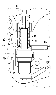
An automatic choke device 1 shown in FIG. 1 is mounted on a carburetor
installed in an
ordinary engine, not shown, and is provided with a temperature sensitive
actuator 2
enclosing an outwardly projectable piston 21, and a butterfly-type choke valve
32 that
3
CA 02761721 2011-11-10
closes an air intake path 31. When the piston 21 of the temperature sensitive
actuator 2
projects outward, it closes the choke valve 32 through a link mechanism 33.
As shown in FIG. 2, the temperature sensitive actuator 2 is provided with two
electrical terminals, a first terminal 41 and a second terminal 42, spaced
apart at an
interval along the longitudinal axis of the piston 2. To each of the terminals
41, 42 are
connected lead wires 43a, 43b. The temperature sensitive actuator 2 is
energized
through the two terminals 41, 42, a thermo-element composed of a PTC heater
disposed within a casing 24 heats up, and the wax expands, projecting the
piston 21.
A pair of fixing protrusions 41a is formed on the forward end electrical
terminal 41.
An attaching portion 11 for attaching the temperature sensitive actuator 2 is
provided to
the automatic choke device 1. The attaching portion 11 is configured as a
substantially
rectangular convex wall portion 12, and inside this convex wall portion 12 is
attached
the temperature sensitive actuator 2.
A cutout 13 that accommodates the piston 21 is provided in the forward end of
the convex wall portion 12. In addition, openings 14 that accommodate the pair
of fixing
protrusions 41 a are formed in the sides of the convex wall portion 12. Each
of the
openings 14 is provided with a rearward facing concave portion 14a. A cutout
16 that
abuts the temperature sensitive actuator 2 casing 24 to position the
temperature
sensitive actuator 2 is provided in the rear end of the convex wall portion
12.
The tip of the piston 21 is formed with a reduced diameter, by which a stepped
portion 21a is formed. In addition, attached to the piston 21 is a bearing
member 22
that is engaged by the stepped portion 21 a near the tip of the piston 21 and
bears an
elastic member 23 composed of a return spring via a flange 22b provided to the
rear
end of the piston 21.
The elastic member 23 composed of a return spring is disposed between the
flange 22b and an inner face of the forward end of the convex wall portion 12.
The
elastic member 23 biases the piston rearward to a non-projecting state through
the
bearing 22 that is engaged by the stepped portion of the piston 21.
The fixing protrusions 41 a of the temperature sensitive actuator 2 are biased
by
the elastic member 23 and abut the read end face of the concave portions 14a.
By so
4
CA 02761721 2011-11-10
doing, the temperature sensitive actuator 2 is prevented from moving axially
with
respect to the automatic choke device 1.
Moreover, by positioning the pair of fixing protrusions 41a of the temperature
sensitive actuator 2 within the concave portions 14a, the temperature
sensitive actuator
2 is prevented from rotating within the convex wall portion 12 as well as from
falling out
of the convex wall portion 12.
With the temperature sensitive actuator 2 attaching structure of the first
embodiment, the temperature sensitive actuator 2 is strongly fixedly mounted
within the
convex wall portion 12 by the elastic member 23, the fixing protrusions 41 a,
41 a, and
the concave portions 14a, 14a. As a result, the temperature sensitive actuator
2 is
reliably prevented from falling out of the convex wall portion 12 due to
vibration or the
like, and further, compared to the conventional screw-stopped actuator, the
ease with
which it is possible to assemble the temperature sensitive actuator 2 is
improved.
Moreover, since there is no need for the space used for screwing the actuator
in
place as in the conventional case, there is greater range of choices available
for the
location of the temperature sensitive actuator 2 and at the same time it is
possible to
make the automatic choke device 1 more compact. In addition, because the
casing 24
of the temperature sensitive actuator 2 abuts the cutout 16 in the rear end of
the convex
wall portion 12, the temperature sensitive actuator 2 is positioned in place.
This
positioning, together with the fixing protrusions 41 a, 41 a and the concave
portions 14a,
14a, can prevent the temperature sensitive actuator 2 from tilting within the
convex wall
portion 12.
It is to be noted that although in the first embodiment a description is given
of a
case in which the thing to which the temperature sensitive actuator 2 is to be
attached is
the automatic choke device 1, the thing to which the temperature sensitive
actuator 2 is
to be attached is not limited thereto.
Second Embodiment
Next, with reference to FIGS. 5-9, a description is given of a temperature
sensitive actuator attaching structure according to a second embodiment of the
present
invention. As with the first embodiment, the temperature sensitive actuator 2
of the
CA 02761721 2011-11-10
second embodiment is one that is attached to an automatic choke device 1.
Elements
that are the same as those of the first embodiment are given the same
reference
numerals and a description thereof is omitted.
It is to be noted that the temperature sensitive actuator 2 of the second
embodiment, like the temperature sensitive actuator 2 of the first embodiment,
is
energized through two electrical terminals 41, 42, a thermo-element 51
composed of a
PTC heater disposed within a casing 24 (see FIG. 8 and FIG. 9) heats up, and
wax W
(see FIG. 8 and FIG. 9) expands, projecting the piston 21 outward.
As shown in FIG. 5, in the temperature sensitive actuator 2 of the second
embodiment a pair of fixing protrusions 42a, 42a is also provided on the rear
end
electrical terminal 42. In addition, as shown in FIGS. 6-9, instead of the
cutout 16 of the
first embodiment a pair of openings 15, 15 that accommodate the fixing
protrusions 42a,
42a are formed in the side wall of the convex wall portion 12 of the second
embodiment.
The openings 15, 15 are each provided with a rearward facing concave portion
15a, 15a.
The tip of the piston 21 is formed with a reduced diameter, thus forming a
stepped portion 21 a. In addition, attached to the piston 21 is a bearing
member 22 that
is engaged by the stepped portion 21 a near the tip of the piston 21 and bears
an elastic
member 23 composed of a return spring via a flange 22b provided to the rear
end of the
piston 21.
The elastic member 23 composed of a return spring is disposed between the
flange 22b and an inner face of the forward end of the convex wall portion 12.
The
elastic member 23 biases the piston rearward to a non-projecting state through
the
bearing 22, which is engaged by the stepped portion of the piston 21.
The fixing protrusions 41a of the temperature sensitive actuator 2 are biased
by
the elastic member 23 and abutted against the rear end face of the concave
portions
14a. By so doing, the temperature sensitive actuator 2 is prevented from
moving axially
with respect to the automatic choke device 1.
The fixing protrusions 41 a, 42a are positioned inside the openings 14a, 15a,
so
that the temperature sensitive actuator 2 is prevented from rotating within
the convex
wall portion 12 as well as from falling out of the convex portion 12.
6
CA 02761721 2011-11-10
With the attaching structure of the temperature sensitive actuator 2 according
to
the second embodiment, the temperature sensitive actuator 2 is strongly
fixedly
mounted within the convex wall portion 12 by the elastic member 23, the fixing
protrusions 41 a, 42a, and the concave portions 14a, 15a. As a result, the
temperature
sensitive actuator 2 is reliably prevented from falling out of the convex wall
portion 12
due to vibration or the like, and further, compared to the conventional screw-
stopped
actuator, the ease with which it is possible to assemble the temperature
sensitive
actuator 2 is improved. Moreover, since there is no need for the space used
for
screwing the actuator in place as in the conventional case, there is greater
range of
choices available for the location of the temperature sensitive actuator 2 and
at the
same time it is possible to make the automatic choke device 1 more compact.
In addition, the fixing protrusions 41a are abutted against the rear end faces
of
the concave portions 14a by the elastic member 23, and the fixing projections
42a are
spaced an interval apart from the rear end face of the concave portions 15a.
As a result,
matters are arranged so that it is possible to accomplish accurate positioning
with the
rear end faces of the concave portions 14a alone, and not only is it possible
to design
the depth of the concave portions 15a so as to create a gap with respect to
the fixing
protrusions 42a but it is also possible to form the concave portions 15a with
ease.
It is to be noted that it is also possible to achieve the same effect with
concave
portions 14a, 15a formed so that the fixing protrusions 42a abut the rear end
faces of
the concave portions 15a while the fixing protrusions 41a are space an
interval apart
from the rear end faces of the concave portions 14a.
Moreover, although in the second embodiment a description is given of a case
in
which the thing to which the temperature sensitive actuator 2 is to be
attached is the
automatic choke device 1, the thing to which the temperature sensitive
actuator 2 is to
be attached is not limited thereto.
Third Embodiment
As a third embodiment, as shown in FIG. 7, the openings 14, 15 may be formed
as slits and the fixing protrusions 41 a, 42a simply pressed into the openings
14, 15 to fix
7
CA 02761721 2011-11-10
the temperature sensitive actuator 2 in place. The concave portions 14a, 15a
of the
second embodiment are not provided to the openings 14, 15 of the third
embodiment.
8