Note: Descriptions are shown in the official language in which they were submitted.
CA 02762406 2011-11-17
WO 2010/104732 PCT/US2010/026179
1
CONTROLLING THE SYNTHESIS GAS COMPOSITION OF A STEAM
METHANE REFORMER
CROSS-REFERENCE TO RELATED APPLICATIONS
[0001] This application is a continuation-in-part of, and claims the benefit
of, Patent Application Serial No. 111879,241, filed July 16, 2007, which is a
continuation-in-part of, and claims the benefit of, Patent Application Serial
No.
11/489,298, filed July 18, 2006; is a continuation-in-part of, and claims the
benefit
of, Patent Application Serial No. 10/911,348, filed August 3, 2004, which is a
continuation-in-part of, and claims the benefit of US Patent 7,208,530 which
was
reissued as RE40419, which claims the benefit of Provisional application
60/355,405, filed February 5, 2002; is a continuation-in-part of, and claims
the
benefit of, Patent Application Serial No. 111879,266, filed July 16, 2007,
which is
a continuation-in-part of, and claims the benefit of, Application Serial No.
11/489,308, filed July 18, 2006; is a continuation-in-part of, and claims the
benefit
of, Patent Application Serial No. 121286165, filed September 29, 2008, which
is a
continuation-in-part of, and claims the benefit of, Application Serial No.
11/879,456 filed July 16, 2007, which is a continuation-in-part of, and claims
the
benefit of, Application Serial No.11/489,299 filed July 18, 2006; is a
continuation-
in-part of, and claims the benefit of, Patent Application Serial No.
12/218,653,
filed July 16, 2008, which is a continuation-in-part of, and claims the
benefit of
Patent Application Serial No. 11/879,267, filed July 16, 2007, which is a
continuation-in-part of, and claims the benefit of, Application Serial No.
111489,353, filed July 18, 2006; and is a continuation-in-part of, and claims
the
benefit of, Patent Application Serial No. 11/635,333, filed December 6, 2006.
[0002] All of the above cited applications are incorporated herein by
reference in their entirety.
FIELD OF THE INVENTION
[0003] The field of the invention is the production of synthesis gas.
CA 02762406 2011-11-17
WO 2010/104732 PCT/US2010/026179
2
BACKGROUND OF THE INVENTION
[0004] There is a need to identify new sources of chemical energy and
methods for its conversion into alternative transportation fuels, driven by
many
concerns including environmental, health, safety issues, and the inevitable
future
scarcity of petroleum-based fuel supplies. The number of internal combustion
engine fueled vehicles worldwide continues to grow, particularly in the
midrange
of developing countries. The worldwide vehicle population outside the U.S.,
which mainly uses diesel fuel, is growing faster than inside the U.S. This
situation
may change as more fuel-efficient vehicles, using hybrid and/or diesel engine
technologies, are introduced to reduce both fuel consumption and overall
emissions. Since the resources for the production of petroleum-based fuels are
being depleted, dependency on petroleum will become a major problem unless
non-petroleum alternative fuels, in particular clean-burning synthetic diesel
fuels,
are developed. Moreover, normal combustion of petroleum-based fuels in
conventional engines can cause serious environmental pollution unless strict
methods of exhaust emission control are used. A clean burning synthetic diesel
fuel can help reduce the emissions from diesel engines.
[0005] The production of clean-burning transportation fuels requires either
the reformulation of existing petroleum-based fuels or the discovery of new
methods for power production or fuel synthesis from unused materials. There
are
many sources available, derived from either renewable organic or waste
carbonaceous materials. Utilizing carbonaceous waste to produce synthetic
fuels
is an economically viable method since the input feed stock is already
considered
of little value, discarded as waste, and disposal is often polluting.
Alternatively,
one can use coal as a feedstock to upgrade low grade dirty solid fuel to a
value
added convenient clean liquid fuel, such as high quality, environment friendly
synthetic diesel or other hydrocarbon fuels.
[0006] Liquid transportation fuels have inherent advantages over gaseous
fuels, having higher energy densities than gaseous fuels at the same pressure
and temperature. Liquid fuels can be stored at atmospheric or low pressures
CA 02762406 2011-11-17
WO 2010/104732 PCT/US2010/026179
3
whereas to achieve liquid fuel energy densities, a gaseous fuel would have to
be
stored in a tank on a vehicle at high pressures that can be a safety concern
in the
case of leaks or sudden rupture. The distribution of liquid fuels is much
easier
than gaseous fuels, using simple pumps and pipelines. The liquid fueling
infrastructure of the existing transportation sector ensures easy integration
into
the existing market of any production of clean-burning synthetic liquid
transportation fuels.
[0007] The availability of clean-burning liquid transportation fuels is a
national priority. Producing synthesis gas (a mixture of hydrogen and carbon
monoxide, also referred to as "syngas") cleanly and efficiently from
carbonaceous
sources, that can be subjected to a Fischer-Tropsch type process to produce
clean and valuable synthetic gasoline and diesel fuels, will benefit both the
transportation sector and the health of society. A Fischer-Tropsch type
process
or reactor, which is defined herein to include respectively a Fischer-Tropsch
process or reactor, is any process or reactor that uses synthesis gas to
produce a
liquid fuel. Similarly, a Fischer-Tropsch type liquid fuel is a fuel produced
by such
a process or reactor. A Fischer-Tropsch type process allows for the
application of
current state-of-art engine exhaust after-treatment methods for NO, reduction,
removal of toxic particulates present in diesel engine exhaust, and the
reduction
of normal combustion product pollutants, currently accomplished by catalysts
that
are poisoned quickly by any sulfur present, as is the case in ordinary stocks
of
petroleum derived diesel fuel, reducing the catalyst efficiency. Typically,
Fischer-
Tropsch type liquid fuels, produced from synthesis gas, are sulfur-free,
aromatic
free, and in the case of synthetic diesel fuel have an ultrahigh cetane value.
[0008] Biomass material is the most commonly processed carbonaceous
waste feed stock used to produce renewable fuels. Waste plastic, rubber,
manure, crop residues, forestry, tree and grass cuttings and biosolids from
waste
water (sewage) treatment are also candidate feed stocks for conversion
processes. Biomass feed stocks can be converted to produce electricity, heat,
valuable chemicals or fuels. California tops the nation in the use and
CA 02762406 2011-11-17
WO 2010/104732 PCT/US2010/026179
4
development of several biomass utilization technologies. Each year in
California,
more than 45 million tons of municipal solid waste is discarded for treatment
by
waste management facilities. Approximately half this waste ends up in
landfills.
For example, in just the Riverside County, California area, it is estimated
that
about 4000 tons of waste wood are disposed of per day. According to other
estimates, over 100,000 tons of biomass per day are dumped into landfills in
the
Riverside County collection area. This municipal waste comprises about 30%
waste paper or cardboard, 40% organic (green and food) waste, and 30%
combinations of wood, paper, plastic and metal waste. The carbonaceous
components of this waste material have chemical energy that could be used to
reduce the need for other energy sources if it can be converted into a clean-
burning fuel. These waste sources of carbonaceous material are not the only
sources available. While many existing carbonaceous waste materials, such as
paper, can be sorted, reused and recycled, for other materials, the waste
producer would not need to pay a tipping fee, if the waste were to be
delivered
directly to a conversion facility. A tipping fee, presently at $30-$35 per
ton, is
usually charged by the waste management agency to offset disposal costs.
Consequently not only can disposal costs be reduced by transporting the waste
to
a waste-to-synthetic fuels processing plant, but additional waste would be
made
available because of the lowered cost of disposal.
[0009] The burning of wood in a wood stove is a simple example of using
biomass to produce heat energy. Unfortunately, open burning of biomass waste
to obtain energy and heat is not a clean and efficient method to utilize the
calorific
value. Today, many new ways of utilizing carbonaceous waste are being
discovered. For example, one way is to produce synthetic liquid transportation
fuels, and another way is to produce energetic gas for conversion into
electricity.
[0010] Using fuels from renewable biomass sources can actually decrease
the net accumulation of greenhouse gases, such as carbon dioxide, while
providing clean, efficient energy for transportation. One of the principal
benefits
of co-production of synthetic liquid fuels from biomass sources is that it can
CA 02762406 2011-11-17
WO 2010/104732 PCT/US2010/026179
provide a storable transportation fuel while reducing the effects of
greenhouse
gases contributing to global warming. In the future, these co-production
processes could provide clean-burning fuels for a renewable fuel economy that
could be sustained continuously.
[0011] A number of processes exist to convert biomass and other
carbonaceous materials to clean-burning transportation fuels, but they tend to
be
too expensive to compete on the market with petroleum-based fuels, or they
produce volatile fuels, such as methanol and ethanol that have vapor pressure
values too high for use in high pollution areas, such as the Southern
California
air-basin, without legislative exemption from clean air regulations. An
example of
the latter process is the Hynol Methanol Process, which uses hydro-
gasification
and steam reformer reactors to synthesize methanol using a co-feed of solid
carbonaceous materials and natural gas, and which has a demonstrated carbon
conversion efficiency of >85% in bench-scale demonstrations.
[00121 Synthesis gas can be produced through one of two major chemical
processes, steam reforming and partial oxidation. Steam reforming is used when
the feed consists of light hydrocarbons such as natural gas, and when hydrogen
is the main product. Partial oxidation is used with heavier feeds, or when a
relatively high yield of carbon monoxide is desired. Table 1 summarizes
various
commercial processes under operation for the production of synthesis gas [1].
Table 1
Syngas Ratio
Chemical Process Feedstock (H2/Co, mole)
Steam Reforming Natural gas, steam 4.76
Steam Reforming Methane, steam 3
Steam Reforming Naptha, steam 2
Steam Reforming Natural gas, C02, steam 2
Partial Oxidation Coal, steam, 02 0.68
Partial Oxidation Coal, steam, 02 0.46
Partial Oxidation Coal, steam, 02 2.07
CA 02762406 2011-11-17
WO 2010/104732 PCT/US2010/026179
6
[0013] The ratio of hydrogen to carbon monoxide in the synthesis gas is
called the syngas ratio and is strongly dependent on the process used and the
nature of the feedstock.
[0014] Syngas is used as a feedstock in the manufacture of various
chemicals and also in the gas-to-liquid processes, which use the Fischer-
Tropsch
type synthesis (FTS) to produce liquid fuels. Alternatively, syngas can be
used in
the so called integrated gasification combined cycle, where it is directly
burned
with air to produce the heat necessary to operate steam turbines used in
electricity generation. Depending on the desired usage, the H2/Co ratio of
syngas
needs to be adjusted. Table 2 summarizes the optimum syngas ratios required
for different processes [2].
Table 2
Syngas Ratio
Required
Desired Product Chemical Process (H2/Co, mole)
Synthetic fuels FTS - Co catalyst 2.05-2.15
Synthetic fuels FTS -- Fe catalyst 1.65
Methanol 2
Ethylene glycol 1.5
Acetic acid 1
Benzene-toluene-xylene 1.5
[0015] In general, the syngas ratio can be lowered by using the pressure
swing adsorption process or by using hydrogen membrane systems.
Alternatively, adding a downstream water-gas shift reactor can increase the
syngas ratio.
[0016] A process was developed in our laboratories to produce synthesis
gas in which a slurry of particles of carbonaceous material in water, and
hydrogen
from an internal source, are fed into a hydro-gasification reactor under
conditions
to generate rich producer gas. This is fed along with steam into a steam
pyrolytic
reformer under conditions to generate synthesis gas. This process is described
in detail in Norbeck et al. U.S. Patent Application Serial No. 10/503,435
CA 02762406 2011-11-17
WO 2010/104732 PCT/US2010/026179
7
(published as US 2005/0256212), entitled: "Production Of Synthetic
Transportation Fuels From Carbonaceous Material Using Self-Sustained Hydro-
Gasification." In a further version of the process, using a steam hydro-
gasification
reactor (SHR) the carbonaceous material is heated simultaneously in the
presence of both hydrogen and steam to undergo steam pyrolysis and hydro-
gasification in a single step. This process is described in detail in Norbeck
et al.
U.S. Patent Application Serial No. 10/911,348 (published as US 2005/0032920),
entitled: "Steam Pyrolysis As A Process to Enhance The Hydro-Gasification of
Carbonaceous Material." The disclosures of U.S. Patent Application Serial Nos.
10/503,435 and 10/911,348 are incorporated herein by reference.
[0017] Producing synthesis gas via gasification and producing a liquid fuel
from synthesis gas are totally different processes. Of particular interest to
the
present invention is the production of synthesis gas using a steam methane
reformer (SMR), a reactor that is widely used to produce synthesis gas for the
production of liquid fuels and other chemicals. The reactions taking place in
the
SMR can be written as follows.
CH 4+H 20 fj CO+3H 2 (1)
or
CH 4+2H 2011 CO 2+4H 2 (2)
Carbon monoxide and hydrogen are produced in the SMR by using steam and
methane as the feed. Heating process water in a steam generator produces the
required steam. The methane is usually supplied in the form of compressed
natural gas, or by means of a light molecular weight off-gas stream from a
chemical or refinery process.
BRIEF SUMMARY OF THE INVENTION
[0018] This invention provides an improved, economical alternative method
to supply steam and methane to an SMR, and to control the synthesis gas
composition obtained from the SMR . This is accomplished by a combination of
CA 02762406 2011-11-17
WO 2010/104732 PCT/US2010/026179
8
new procedures, wherein product gas from an SHR is used as the feedstock for
the SMR by removing impurities from the product stream from the SHR with a gas
cleanup unit that operates at process pressures and is located in between the
SHR and SMR.
[0019] In one embodiment of the invention, product gas from an SHR is
used as the feedstock for the SMR. As described above, this steam and methane
rich product gas is generated by means of hydro-gasification of the slurry,
which
is a mixture of carbonaceous material and water. This product gas, a mixture
of
methane rich gas and steam, where the steam is present as a result of the
superheating the water in the feedstock, serves as an ideal feed stream for
the
SMR. The SMR requires no other input of gases other than the mixture of
methane rich gas and steam produced by hydrogasifier.
[0020] The other procedure requires removing impurities from the product
stream from hydrogasifiers, such as fine particles of ash & char, hydrogen
sulfide
(H2S) and other inorganic components. These impurities must be removed in
order to prevent poisoning of the catalyst used in the SMR. Conventionally, a
combination of particulate filters, a solvent wash (amines, SelexoIT",
RectisoF'),
and hydro-desulphurization by means of the Claus process are used for this
purpose. In the Claus process, H2S is partially oxidized with air in a
reaction
furnace at high temperatures (1000-1400 deg C). Sulfur is formed, but some H2S
remains unreacted, and some SO2 is made requiring that the remaining H2S be
reacted with the SO2 at lower temperatures (about 200-350 deg C) over a
catalyst
to make more sulfur. However, because the SMR feed stream needs to be
maintained high temperatures, these conventional clean-up techniques are
prohibitive from an energy viewpoint, since the re-heating of the gas stream
consumes a significant amount of energy. Moreover, the benefits supplied by
retaining the steam from the SHR product stream are lost. Accordingly, in
another embodiment of the invention, a gas cleanup unit is provided that
operates
at process pressures and is located in between the SHR and SMR.
CA 02762406 2011-11-17
WO 2010/104732 PCT/US2010/026179
9
[0021] More particularly, a process is provided for converting
carbonaceous material to synthesis gas, comprising simultaneously heating
carbonaceous material in the presence of both hydrogen and steam, at a
temperature and pressure sufficient to generate a stream of methane and carbon
monoxide rich gas product, which can be called a producer gas. Impurities are
removed from the producer gas stream substantially at the process pressure at
a
temperature above the boiling point of water at the process pressure, and the
resultant producer gas is subjected to steam methane reforming under
conditions
whereby synthesis gas comprising hydrogen and carbon monoxide is generated.
In a specific process, for converting municipal waste, biomass, biosolids,
wood,
coal, or a natural or synthetic polymer to synthesis gas, the carbonaceous
material is simultaneously heated in the presence of both hydrogen and steam,
at
a temperature of about 700 C to about 900 C and pressure about 132 psi to 560
psi whereby to generate a stream of methane and carbon monoxide rich producer
gas. Impurities are removed from the producer gas stream at the process
pressure and at a temperature above the boiling point of water at the process
pressure (which can be substantially at the process temperature), following
which
the resultant producer gas is subjected to steam methane reforming under
conditions whereby to generate synthesis gas comprising hydrogen and carbon
monoxide at a H 2: CO mole ratio range of about 3 to 1. The required H2:CO
mole
ratio of a Fischer-Tropsch type reactor with a cobalt based catalyst is 2:1.
Accordingly, there is an excess of hydrogen, which can be separated and fed
into
the SHR to make a self-sustainable process, i,e., without requiring an
external
hydrogen feed. The synthesis gas generated by the steam methane reforming
can be fed into a Fischer-Tropsch type reactor under conditions whereby a
liquid
fuel is produced. Exothermic heat from the Fischer-Tropsch type reaction can
be
transferred to the hydro-gasification reaction and/or steam methane reforming
reaction.
[0022] In a further embodiment, a method for enhancing the operability of
hot gas cleanup of methane rich producer gas is provided. This is-accomplished
by changing the sequence of the process to a sequence comprising:
CA 02762406 2011-11-17
WO 2010/104732 PCT/US2010/026179
[0023] -- steam-hydrogasification;
[0024] -- autothermal reforming of methane;
[0025] -- steam removal by condensation; then
[0026] -- hot gas cleanup.
[0027] More particularly, a process is provided for enhancing the
operability of hot gas cleanup for the production of synthesis gas in which a
stream of methane rich gas is autothermally reformed at a temperature and
pressure sufficient to generate a stream of synthesis gas rich in hydrogen and
carbon monoxide, about 550 C to about 750 C. The synthesis gas is subjected
to condensation and removing the resultant water, and sulfur impurities are
removed from the resultant synthesis gas stream in the absence of moisture,
which condition is favorable to sulfur capture by the sorbents. The synthesis
gas
stream resulting from condensation is heated to substantially the temperature
at
which the impurities are removed from the synthesis gas stream, about 250 C
to
about 400 C.
[0028] The stream of methane rich producer gas can be produced from
separate steam pyrolysis and hydro-gasification reactors, but preferably, the
stream of methane rich producer gas is produced from steam-hydrogasification
before being subjected to autothermal reforming. Again preferably, the
pressure
of the steam-hydrogasification, autothermal reforming, condensation, and
sulfur
impurity removal is substantially the same throughout, about 150 psi to 500
psi.
[0029] In another embodiment, an apparatus is provided for converting
carbonaceous material to synthesis gas, comprising a steam-hydrogasification
reactor for simultaneously heating carbonaceous material with liquid water in
the
presence of both hydrogen and steam, at a temperature and pressure sufficient
to
generate a stream of methane rich gas, and autothermal methane reforming
means to generate a stream of synthesis gas rich in hydrogen and carbon
monoxide, means for condensing subjecting said synthesis gas to condensation,
CA 02762406 2011-11-17
WO 2010/104732 PCT/US2010/026179
11
whereby synthesis gas is substantially devoid of water, and means for removing
sulfur impurities from the said synthesis gas stream devoid of water.
[0030] The apparatus can include a Fischer-Tropsch type reactor for
receiving the purified generated synthesis gas to produce a liquid fuel. Means
can be provided for transferring exothermic heat from the Fischer-Tropsch type
reaction to the steam-hydrogasification reactor and/or autothermal methane
reforming means.
[0031) In yet another embodiment, this invention provides an improved,
economical method to control the synthesis gas composition obtained from a
steam methane reformer that obtains its feedstock as product gas directly from
a
steam hydro-gasification reactor. The method allows control of the H2/CO ratio
by
predetermining/adjusting the hydrogen feed and the water content of feedstock
into the SHR that supplies the SMR. In a particular embodiment, H2: CO mole
ratio of about 0.5:1 to 16:1 and more particularly of about 1:1 to 6:1 can be
produced as a result of adjusting/predetermining the hydrogen feed and the
water
content of feedstock into the SHR.
[0032] To control the sygnas ratio, one of two methods are used to adjust
the hydrogen feed. In one embodiment, the hydrogen is obtained by diverting a
portion of hydrogen separated from the synthesis gas to the slurry water. In
another, preferred embodiment, the hydrogen is obtained by diverting a portion
of the synthesis gas itself to the hydrogasification reactor, without
separating
hydrogen from the synthesis gas. By controlled recycling, using a portion of
the
synthesis gas, a steady state desired H2/ H2O ratio is obtained, which occurs
quite rapidly.
[0033] As described above, the steam and methane rich product gas of the
SHR is generated by means of hydro-gasification of the slurry, which is a
mixture
of carbonaceous material and water. This product gas, a mixture of methane
rich
gas and steam, where the steam is present as a result of the superheating the
water in the feedstock, serves as an ideal feed stream for the SMR. Impurities
CA 02762406 2011-11-17
WO 2010/104732 PCT/US2010/026179
12
such as fine particles of ash & char, hydrogen sulfide and other inorganic
components are removed from the SHR product stream, for instance using some
of the embodiments disclosed above.
[0034] The mass percentages of the product stream at each stage of the
process are calculated using a modeling program, such as the ASPEN PLUSTM
equilibrium process that can relate the synthesis gas ratio of hydrogen to
carbon
monoxide to conversion ratios of the carbon content of the carbonaceous
material. In accordance with the invention, by varying the parameters of solid
to
water ratio and hydrogen to carbon ratio, a sensitivity analysis can be
performed
that enables one determine the optimum composition of the slurry feedstock to
the SHR to obtain a desired syngas ratio output of the SMR. Thus, the ratio of
hydrogen to slurry water is determined by analysis of the effect on the
synthesis
gas ratio of (a) the ratio of solid content of the carbonaceous material to
the slurry
water and (b) the ratio of the hydrogen to carbon content of the carbonaceous
material. This enables one to adjust the hydrogen feed and the water content
of
feedstock into the SHR that supplies the SMR to provide the desired ratio of
hydrogen to carbon monoxide in the synthesis gas output of the SMR.
[0035] More particularly, a process is provided for converting
carbonaceous material to synthesis gas, comprising simultaneously heating
carbonaceous material in an SHR in the presence of a predetermined ratio of
hydrogen and water in the form of steam, at a temperature and pressure
sufficient
to generate a stream of methane and carbon monoxide rich gas product, which
can be called a producer gas. Impurities are removed from the producer gas
stream substantially at the process temperature and pressure (either by hot
gas
cleanup alone or in combination with autothermal reforming and condensation),
and the resultant producer gas is subjected to steam methane reforming in an
SMR under conditions whereby synthesis gas comprising hydrogen and carbon
monoxide is generated having a hydrogen/carbon monoxide ratio determined by
the ratio of hydrogen and water in the SHR. While the hydrogen can be obtained
by diverting a portion of hydrogen separated from the synthesis gas to the
slurry
CA 02762406 2011-11-17
WO 2010/104732 PCT/US2010/026179
13
water, it is preferred to obtain the hydrogen by diverting a portion of the
synthesis
gas itself, without separation of hydrogen from the synthesis gas, to the
slurry
water.
BRIEF DESCRIPTION OF THE DRAWINGS
[0036] For a more complete understanding of the present invention,
reference is now made to the following descriptions taken in conjunction with
the
accompanying drawing, in which:
[0037] Figure 1 is a flow diagram of the process of this invention in
accordance with a first embodiment in which hydrogen is separated from a
portion of the SMR output and recirculated;
[0038] Figure 2 is a flow diagram of the mass balance of the process of the
first embodiment;
[0039] Figure 3 is flow diagram of the process of this invention in
accordance with a second embodiment where a portion of the output of the SMR
is itself recycled without separation of its hydrogen;
[0040] Figure 4 is flow diagram of the mass balance of the process in
accordance with the second embodiment before recycling of a portion of the
SMR;
[0041] Figure 5 is flow diagram of the mass balance of the process in
accordance with the second embodiment after recycling a portion of the SMR;
[0042] Figure 6 shows the H2/CO and steam/CH2 molar ratios for each run
in accordance with the second embodiment until after steady values are
achieved;
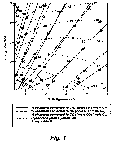
[0043] Figure 7 is a sensitivity analysis using the ASPEN PLUSTM modeling
program showing various conversions and the syngas ratio when parameters of
solid to water ratio and hydrogen to carbon ratio are varied.
CA 02762406 2011-11-17
WO 2010/104732 PCT/US2010/026179
14
[0044] Figure 8 shows the H2/CO syngas ratios obtainable when wood is
used as the feedstock.
[0045] Figure 9 shows the H2/CO syngas ratios obtainable when coal is
used as the feedstock.
[00461 Figure 10 shows a flow diagram of the process of this invention in
accordance with a specific embodiment.
DETAILED DESCRIPTION OF THE INVENTION
[0047] This invention provided several embodiments for improved cleanup
and production of synthesis gas. Regardless of the embodiment, simultaneously
heating of the carbonaceous material in the presence of both hydrogen and
steam (at the steam hydrogasification stage) can occur in the absence of
catalysts, injection of air, oxygen (i.e. partial oxidation conditions), or
other
initiating chemicals.
[0048] In one embodiment of the invention, the feedstock for an SMR is a
mixture of steam and methane rich product gas generated by means of hydro-
gasification of a mixture of carbonaceous material and water in an SHR. The
steam is present as a result of superheating the water in the feedstock and
serves as an ideal feed stream for the SMR.
[0049] In another embodiment, a hot gas cleanup method is provided for
removing impurities from the product stream from the SHR, such as fine
particles
of ash & char, hydrogen sulfide (H 2S) and other inorganic components. These
impurities must be removed in order to prevent poisoning of the catalyst used
in
the SMR while maintaining the SMR feed stream at its high process
temperatures. Accordingly, in another embodiment of the invention, a gas
cleanup unit is provided that operates at the process pressure and at a
temperature above the boiling point of water at the process pressure, and is
located between the SHR and SMR.
CA 02762406 2011-11-17
WO 2010/104732 PCT/US2010/026179
[0050] In a more particularized embodiment, this invention provides
autothermal reforming of methane and steam removal by condensation prior to
the above mentioned hot gas cleanup stage. This process can be used where
there are separate steam pyrolysis and hydro-gasification reactors, or in a
steam
hydrogasification reactor, followed by an autothermal reforming reactor, in a
process for producing a synthesis gas for use as fuel for process heat and/or
in a
fuel engine or gas turbine that can generate electricity; or as feed into a
Fischer-
Tropsch type reactor to produce a liquid paraffinic fuel, recycled water and
sensible heat, in a substantially self-sustaining process.
[0051] In yet another embodiment, a method is provided that enables one
to control of the H2/CO ratio output of an SMR by adjusting the hydrogen feed
and
the water content of feedstock into the SHR that supplies the SMR. The steam
and methane rich product gas of the SHR is generated by means of hydro-
gasification of the slurry, which is a mixture of carbonaceous material and
water.
This product gas, a mixture of methane rich gas and steam, where the steam is
present as a result of the superheating the water in the feedstock, serves as
an
ideal feed stream for the SMR.
[0052] The mass percentages of the product stream at each stage of the
process are calculated using a modeling program, such as the ASPEN PLUS"
equilibrium process. By varying the parameters of solid to water ratio and
hydrogen to carbon ratio, a sensitivity analysis can be performed that enables
one determine the optimum composition of the slurry feedstock to the SHR to
obtain a desired syngas ratio output of the SMR. Thus one can adjust the
hydrogen feed and the water content of feedstock into the SHR that supplies
the
SMR to determine the syngas ratio output of the SMR.
[0053] Impurities are removed from the SHR product stream, such as fine
particles of ash & char, hydrogen sulfide and other inorganic components.
These
impurities must be removed in order to prevent poisoning of the catalyst used
in
the SMR. Conventionally, a combination of particulate filters, a solvent wash
(amines, SelexolTM, RectisolTM), and hydro-desulphurization by means of the
CA 02762406 2011-11-17
WO 2010/104732 PCT/US2010/026179
16
Claus process are used for this purpose. In the Claus process, H2S is
partially
oxidized with air in a reaction furnace at high temperatures (1000 -1400 C).
Sulfur is formed, but some H2S remains unreacted, and some SO2 is made
requiring that the remaining H2S be reacted with the SO2 at lower temperatures
(about 200 - 350 C) over a catalyst to make more sulfur. However, because the
SMR feed stream needs to be maintained at high temperatures, these
conventional clean-up techniques are prohibitive from an energy viewpoint
since
the re-heating of the gas stream consumes a significant amount of energy.
Moreover, the benefits supplied by retaining the steam from the SHR product
stream are lost. Accordingly, to maintain the SMR feed stream at high
temperatures, a gas cleanup unit is provided that operates at process
pressures
and at a temperature above the boiling point of water (or above the steam
condensation point). The unit is located between the SHR and SMR.
[0054] More particularly, a process is provided for converting
carbonaceous material to synthesis gas of a desired H2/CO ratio, comprising
simultaneously heating carbonaceous material in an SHR in the presence of a
predetermined ratio of hydrogen and water in the form of steam, at a
temperature
and pressure sufficient to generate a stream of methane and carbon monoxide
rich gas product, which can be called a producer gas, the ratio of hydrogen
and
water being determined by a modeling program, such as the ASPEN PLUSTM
equilibrium process. In accordance with the invention, by varying the
parameters
of solid to water ratio and hydrogen to carbon ratio, a sensitivity analysis
is
performed that enables one determine the optimum composition of the slurry
feedstock to the SHR to obtain a desired syngas ratio output of the SMR.
Impurities are removed from the producer gas stream substantially at the
process
temperature and pressure, and the resultant producer gas is subjected to steam
methane reforming in an SMR under conditions whereby synthesis gas
comprising hydrogen and carbon monoxide is generated having a
hydrogen/carbon monoxide ratio determined by the ratio of hydrogen and water
in
the SHR.
CA 02762406 2011-11-17
WO 2010/104732 PCT/US2010/026179
17
[0055] In a specific process, for converting municipal waste, biomass,
wood, coal, biosolids, or a natural or synthetic polymer to synthesis gas, the
carbonaceous material is simultaneously heated in the presence of both
hydrogen and steam, at a temperature of about 700 C to about 900 C and
pressure about 132 psi to 560 psi whereby to generate a stream of methane and
carbon monoxide rich producer gas. Steam can come from the feedstock or
introduced separately. Impurities are removed from the producer gas stream
substantially at the process temperature and pressure, following which the
resultant producer gas is subjected to steam methane reforming under
conditions
whereby to generate the desired synthesis gas ratio of hydrogen and carbon
monoxide. For example, the required H2:CO mole ratio of a Fischer-Tropsch type
reactor with a cobalt based catalyst is 2.1:1. By appropriate adjustment, as
described below, of the H2/ H2O ratio, a H2/CO mole ratio range of about 3 to
1
can be achieved to provide an excess of hydrogen, which can be fed into the
SHR to make a self-sustainable process, i.e., without requiring any external
hydrogen feed. The synthesis gas generated by the steam methane reforming
can be fed into a Fischer-Tropsch type reactor under conditions whereby a
liquid
fuel is produced. Exothermic heat from the Fischer-Tropsch type reaction can
be
transferred to the hydro-gasification reaction and/or steam methane reforming
reaction.
[0056] In one embodiment, the hydrogen is obtained by diverting a portion
of hydrogen separated from the synthesis gas to the slurry water. In another,
preferred embodiment, the hydrogen is obtained by diverting a portion of the
synthesis gas itself to the slurry water, without separation of hydrogen from
the
synthesis gas. By controlled recycling, using a portion of the synthesis gas,
a
steady state desired H2/ H2O ratio is obtained, which occurs quite rapidly.
Example 1
[0057] Figure 1 is a flow diagram a SHR to SMR process one embodiment
of the invention in which a desired H2/CO ratio output of an SMR is obtained
by
separating hydrogen from the SMR output, diverting it to the HGR, and
adjusting
the hydrogen feed and the water content of feedstock into the SHR that
supplies
CA 02762406 2011-11-17
WO 2010/104732 PCT/US2010/026179
18
the SMR. An internally generated hydrogen feed 10 is fed into an SHR 12 along
with a carbonaceous feedstock 14 and water 16, which are heated to 750 C at
400 psi in the SHR 12. The resulting producer gas is directed to a gas clean
up
filter 18, e.g. a candle filter assembly, at about 350 C at about 400 psi.
From
there, after removal of sulfur and ash, the effluent is directed to an SMR 20
where
synthesis gas is generated and fed to a Fischer-Tropsch type reactor 22, from
which pure water 24, and diesel fuel and/or wax 26 is obtained. The SMR 20
output is passed through a hydrogen separator 27 where a portion of its
hydrogen
is separated and diverted from the SMR 20, at 28 to be fed back to the HGR 12.
Heat 30 from the Fischer-Tropsch type reactor 22 is used to supplement the
heat
at the SMR.
[0058] Operating the unit above the bubbling temperature of the water
allows the water to be present as steam in the gaseous product stream from the
SHR, thereby enabling the process to retain most of the sensible heat in the
effluent stream. The following example will illustrate the invention.
[0059] A mass balance process flow diagram is shown in Figure 2. The
mass percentages of the product stream at each stage of the process are
provided in the figure. ASPEN PLUSH equilibrium process modeling was used
to calculate these values. ASPEN PLUST"' is a commercial computer modeling
program that allows a process model to be created by specifying the chemical
components and operating conditions. The program takes all of the
specifications
and simulates the model, executing all necessary calculations needed to solve
the outcome of the system, hence predicting its behavior. When the
calculations
are complete, ASPEN PLUSTM lists the results, stream by stream and unit by
unit,
and can present the data in graphical form with determining ordinate and
abscissa.
[0060] As shown in Figure 2, an SHR feedstock of hydrogen and 41 % coal
slurry results in the production of synthesis gas with a 3.4: I mole ratio of
hydrogen to carbon monoxide in the SMR. The required feed hydrogen for the
SHR can be supplied through external means or by internal feedback of a
portion
CA 02762406 2011-11-17
WO 2010/104732 PCT/US2010/026179
19
of the hydrogen produced in the SMR. In a particular example, a slurry of 41 %
coal, 52% water and 7 % hydrogen is used, obtained following the procedures of
Norbeck et al. U.S. Serial No. 10/911,348. This results in an output from the
SHR
to the cleanup filter of a gaseous mixture containing 32 wt% CH4, 2 wt% H2, 2
wt% CO, 3 wt% C02, 51 wt% H2O, 4 wt% ash, 5 wt% char, and 1 wt% other
impurities.
[0061] The output of the SHR-cleanup unit is a methane rich, producer
gas containing 36 wt% CH4, 2 wt% H2, 2 wt% CO, 3 wt% C02, and 57 wt% H2O,
having a steam to methane mole ratio of 1:4. The output of the SHR is fed to
the SMR, which is operating at 800 C and 28 atmospheres to yield synthesis gas
having a mole ratio of H2 to CO of 3.4, and containing 4 wt% CH4, 14 wt% H2,
58
wt% CO, 3 wt% C02, and 21 wt% H20-
Example 2
[0062] This Example, shown in Figures 3 - 6, illustrates a second,
preferred embodiment in which a portion of the output of the SMR is itself
recycled. Figure 3 is flow diagram of the SHR to SMR process in which a
desired
H2/CO ratio output of an SMR is obtained by without separating hydrogen from
the SMR output, but diverting a portion of the SMR output itself to the HGR,
and
adjusting the hydrogen feed and the water content of feedstock into the SHR
that
supplies the SMR. The process is the same as described in Example 1 but for
those changes reflecting the direct use of a portion of the SMR as feed to the
SHR. Accordingly, while some hydrogen is used to start the process, as shown
in
Figure 4, discussed below, internally generated hydrogen feed is that
component
of the SMR output, as shown at 10a in Figure 3. As in Example 1, the SMR
portion 10a is fed into an SHR 12 along with a carbonaceous feedstock 14 9nd
water 16, which are heated to 750 C at 400 psi in the SHR 12. The resulting
producer gas is directed to the gas clean up filter 18, and from there, after
removal of sulfur and ash, the effluent is directed to the SMR 20 where
synthesis
gas is generated and fed to a Fischer-Tropsch type reactor 22., from which
pure
water 24, and diesel fuel and/or wax 26 is obtained.
CA 02762406 2011-11-17
WO 2010/104732 PCT/US2010/026179
[0063] In contrast to Example 1, the SMR 20 output is not passed through
a hydrogen separator, but a portion, indicated at 28a is directly diverted
from the
SMR 20 to be fed back to the HGR 12. As in Example 1, heat 30 from the
Fischer-Tropsch type reactor 22 is used to supplement the heat at the SMR.
[0064] A mass balance process flow diagram for the initial run is shown in
Figure 4. As in Example 1, the mass percentages of the product stream at each
stage of the process are provided in the figure, obtained using ASPEN PLUS'
equilibrium process modeling.
[0065] As shown in Figure 4, an initial SHR slurry feedstock containing 4%
hydrogen, 32% coal, and 64% water results in the production of synthesis gas
with a 3.8: I mole ratio of hydrogen to carbon monoxide in the SMR. This
results
in an output from the SHR to the cleanup filter of a gaseous mixture
containing 16
wt% CH4, 3 wt% H2, 5 wt% CO, 23 wt% CO2, 48 wt% H2O, 2 wt% ash, 2 wt%
char, and 0 wt% other impurities.
[0066] The output of the SHR-cleanup unit is a gas containing 17 wt% CH4,
3 wt% H2, 5 wt% CO, 24 wt% C02, and 51 wt% H2O, having a steam to methane
mole ratio of 2:7. The output of the SHR is fed to the SMR, which is operating
at
850 C and 27.2 atmospheres to yield synthesis gas having a mole ratio of H2 to
CO of 3.8, and containing 5 wt% CH4, 8 wt% H2, 28 wt% CO, 21 wt% C02, and
39 wt% H2O.
[0067] Figure 5 shows a mass balance flow diagram after 12 recycle runs
where it reached a final steady H2/CO exit ratio. The steady state feedstock
contained 3% hydrogen, 21 % coal, 42% water, 19%CO, 13%CO2, and 2% CH4,
resulting in the production of synthesis gas with a 1.9: I mole ratio of
hydrogen to
carbon monoxide in the SMR. This results in an output from the SHR to the
cleanup filter of a gaseous mixture containing 16 wt% CH4, 2 wt% H2, 8 wt% CO,
43 wt% CO2, 29 wt% H20, 1 wt% ash, 2 wt% char, and 0 wt% other impurities.
[0068] The output of the SHR-cleanup unit is a gas containing 16 wt% CH4,
2 wt% H2, 9 wt% CO, 44 wt% C02, and 30 wt% H2O, having a steam to methane
CA 02762406 2011-11-17
WO 2010/104732 PCT/US2010/026179
21
mole ratio of 1.6. The output of the SHR is fed to the SMR to yield synthesis
gas
having a mole ratio of H2 to CO of 1.9, and containing 5 wt% CH4, 5 wt% H2, 39
wt% CO, 26 wt% C02, and 24 wt% H20.
[0069] Figure 6 shows the H2/CO and steam/CH2 molar ratios for each run
until after steady values are achieved. This diagram demonstrates the ability
of
the process of this preferred embodiment to produce synthesis gas at a desired
H2ICO ratio through controlled recycling of a fraction of the SMR product
stream.
[0070] In these examples, the filter is operating at 300 C and 28
atmospheres of pressure. Any filter capable of operating at the process
temperature can be used at the gas cleanup station. One such commercially
available filter is a candle filter, which is well known to the art. See, for
example
U.S. Patent No. 5,474,586, the disclosure of which is incorporated herein by
reference. An available gas cleanup unit that can be used in this invention is
what is known as a candle filter in which a series of candle-shaped filters
are
carried in a filter vessel. The candle filters are made of stainless steel
metal frit to
remove fine particulate matter (ash, inorganic salts and unreacted char) from
the
gas stream. The slurry is fed into the vessel at a bottom inlet and filtrate
is taken
out at a top outlet. Particulate matter is taken from another outlet as cake.
Sulfur
impurities existing in the SHR product gas, mostly in the form of hydrogen
sulfide,
are removed by passing the product gas through a packed bed of metal oxide
sorbents in the gas cleanup unit, particulate matter being taken from a cake
outlet.
[0071] Active sorbents include, but are not limited to, Zn based oxides such
as zinc oxide, sold by Sud-Chemie, Louisville, Kentucky. Porous metal filter
elements are available from Bekaert in Marietta, Georgia in the appropriate
forms
and sizes, such as Bekpor Porous Media-which is made from stainless steel
sintered fiber matrix with a pore size of 1. These sorbents and filter
elements
allow the effects of pressure drop and gas-solid mass transfer limitations to
be
minimized. At a pressure of 28 atm., temperatures in the range of 300CC to
500CC
and space velocities up to 2000 /hr have been used in the desulphurization of
CA 02762406 2011-11-17
WO 2010/104732 PCT/US2010/026179
22
SHR product gas. The hydrogen sulfide content of the gas is diminished by
means of sulfidation of the sorbents to levels low enough to avoid the
deactivation
of the SMR catalyst. The used sorbents in the gas cleanup unit can either be
replaced with fresh sorbents or regenerated in-situ with diluted air in
parallel
multiple sorbent beds.
[0072] As described, the syngas ratio obtained from the SMR can be
adjusted by varying the solid to water ratio and hydrogen to carbon ratio in
the
SHR feedstock. Sensitivity analysis was performed using the ASPEN PLUSTM
equilibrium modeling tool by varying these parameters. The results are in
Figure
7, showing various conversions and the syngas ratio when parameters of solid
to
water ratio and hydrogen to carbon ratio are varied. . The solid lines ( )
represent the percentage of carbon converted to CH4 (mole CH4/mole C;,,). The
long dashed lines r; -- - --) represent the percentage of carbon converted to
CO
(mole CO/mole C1 ). The dotted lines ( ................ ) represent the
percentage of
carbon converted to CO2 (mole C02/mole C;n). The dash-dot-dot-dash lines
(- ) represent sustainable H2, and the short dashed lines (- - ` - - - )
represent the syngas ratio of H2/CO (mole H2/mole CO). The H2/C ratio of the
feed is always on a molar basis and the H20/Feed ratio is always on mass
basis.
[0073] The last parameter is of key interest in this invention. Figure 7
clearly demonstrates that the final syngas ratio can be adjusted by adjusting
the
water to solid ratio (represented as H2O! C mass ratio in Figure 7) and the
hydrogen to carbon ratio of the feedstock. Thus, an optimum composition of the
slurry to obtain a sustainable hydrogen feedback and the desired syngas ratio
for
the Fischer-Tropsch synthesis (2.1:1) was found to be 3.1 when the mole ratio
of
hydrogen to carbon in the feed was set to one.
[0074] Figure 8 shows the H2:CO ratio of the SMR product stream being
varied by changing the H2/C and H20/wood ratios of the wood feed. For
instance,
to obtain a desired syngas ratio of about 6:1, a 2:1 ratio of H2/C and 2:1
ratio of
H20/wood of the feed can be used; alternatively, the same syngas ratio can be
obtained usomg a 1:1 ratio of H2/C and 3:1 ratio of H20/wood of the wood feed.
CA 02762406 2011-11-17
WO 2010/104732 PCT/US2010/026179
23
Figure 9 shows the H2:CO ratio of the SMR product stream being varied by
changing the H2/C and H20/coal ratios of the coal feed.
[0075] For simulations performed, the results of which are shown in figures
8 and 9, the temperature of the SHR and SMR was set to be 850 C. All the
reactors were at a pressure of 400 psi. The H2/CO ratios shown in these
figures
are calculated before the separation of excess H2 for recycle to the SHR.
[0076] Similar syngas ratio predeterminations can be made using other
carbonaceous material feedstocks such as, but not limited to, municipal waste,
biomass, biosludge, or a natural or synthetic polymer. Here, the H2/C ratio of
the
feed is always on a molar basis and the H20/Feed ratio is always on mass
basis.
[0077] More generally, the process of this invention can produce
composition of synthesis gas having a H2: CO mole ratio range of about 0.5:1
to
16:1. The resulting effluent is a synthesis of gases rich in hydrogen, carbon
monoxide, and steam. Hydrogen produced in the SMR is recycled back to the
HGR. Consequently, no outside source of hydrogen is needed to maintain steady
state operation. The HGR and SMR processes, therefore, may be considered to
be chemically self-sustaining. The remaining synthesis gas is then available
for
the production of fuels and process heat.
[0078] In an embodiment of the invention, the synthesis gas is fed to a
Fischer-Tropsch reactor in a process that can produce a zero-sulfur, ultrahigh
cetane value diesel-like fuel and valuable paraffin wax products. The absence
of
sulfur enables low pollutant and particle emitting diesel fuels to be
realized.
Useful by-products can be produced, foe example, purified water, which can be
re-cycled to create the slurry feed into the process. The Fischer-Tropsch
reactions also produce tail gas that contains hydrogen, CO, CO 2, and some
light
hydrocarbon gases. Hydrogen can be stripped out of the tail gas and recycled
either to the HGR or the Fischer-Tropsch reactor. Any small amounts of other
gases such as CO and CO may be flared off.
CA 02762406 2011-11-17
WO 2010/104732 PCT/US2010/026179
24
[0079] In yet another embodiment, this invention provides an improved
process scheme that can enhance the operability of hot gas cleanup of steam-
hydrogasification producer gas by insertion of an autothermal reforming of
methane and steam removal by condensation step prior to the hot gas cleanup
step.
[0080] The improved process scheme can be used where there are
separate steam pyrolysis and hydra-gasification reactors, followed by an
autothermal reforming reactor, in a process for producing a synthesis gas for
use
as fuel for process heat and/or in a fuel engine or gas turbine that can
generate
electricity; or as feed into a Fischer-Tropsch type reactor to produce a
liquid
paraffinic fuel, recycled water and sensible heat, in a substantially self-
sustaining
process.
[0081] Preferably, the improved process scheme is used with a steam
hydro-gasification reactor (SHR) in which carbonaceous material is heated in
the
presence of both hydrogen and steam to undergo steam pyrolysis and hydro-
gasification in a single step.
[0082] In other embodiments, this additional step can be used in any
process where methane rich gas is produced.
[0083] In order to adopt this improved process that incorporates
autothermal reforming of methane and steam removal by condensation, a number
of requirements have to be met: (i) the catalyst used for autothermal
reforming of
methane should be able to maintain activity for methane reforming
satisfactorily in
high-sulfur environment, and (ii) the temperature for steam condensation prior
to
hot gas cleanup should not be significantly lower than that for hot gas
cleanup at
the operating pressure so as to enable modest amounts of heat to be added to
bring the resultant gas stream up to substantially the temperature of the hot
gas
cleanup.
[0084] In the preferred embodiment, the first step in the improved process
involves feeding hydrogen, internally generated, into a SHR along with a
CA 02762406 2011-11-17
WO 2010/104732 PCT/US2010/026179
carbonaceous feedstock and liquid water. The resultant producer gas, which is
rich in methane, enters the autothermal reforming reactor. Oxygen diluted with
nitrogen is separately fed to the autothermal reforming reactor: oxygen
content
needs to be preferably about 15% volm to 25% volm.
[0085] Within the autothermal reforming reactor, noble metal catalysts are
preferably used. Compared with the nickel-based catalysts used for steam
reforming of methane, noble metal catalysts used for autothermal reforming of
methane are known to have higher activity and superior sulfur-resistance as
well
as regenerability. Therefore, methane-rich gas produced from steam-
hydrogasification can be reformed with the increased operability by means of
autothermal reforming: the methane-rich gas containing high concentration of
hydrogen sulfide can be reformed to synthesis gas for extended time on stream
and the used catalyst can be regenerated in an inert gas atmosphere. Examples
of noble metal catalysts which can be used are Engelhard's ATR-7B and Haldor
Topsoe's RKS-2-7H or RKS-2P.
[00861 After the autothermal reforming of methane, steam can be removed
from the process by condensation at a temperatures not substantially lower
than
that for hot gas cleanup. In the case of 28 bar operating pressure, steam
condenses to water at 230 C, which can then be removed from the process
stream before it is fed to the stage of hot gas cleanup. By removing the steam
prior to hot gas cleanup, the sulfur capture capacity of the metal oxide
sorbents
used in the hot gas clean up stage can be fully utilized; and the energy load
required to reheat the process stream for hot gas cleanup can be lowered to a
great extent as the specific heat of the process stream decreases
significantly
due to steam removal. For example, optimum temperature for hot gas cleanup by
ZnO sorbent is around 300 C, therefore, the process stream cooled down to 230
C for steam condensation needs to be reheated only by 70 C.
[0087] After removal of the steam, the resulting synthesis gas is directed to
a hot gas cleanup process, as described above.
CA 02762406 2011-11-17
WO 2010/104732 PCT/US2010/026179
26
[0088] Once nitrogen is separated by a gas-separation device for being
recycled to the autothermal reforming reactor, the resulting synthesis gas is
then
available for the production of fuels and process heat, or the synthesis gas
is fed
to a Fischer-Tropsch type reactor in a process that can produce a zero-sulfur,
ultrahigh cetane value diesel-like fuel and valuable paraffin wax products.
The
absence of sulfur enables low pollutant and particle emitting diesel fuels to
be
realized. Useful by-products can be produced, for example, purified water,
which
can be re-cycled to create the slurry feed into the process. The Fischer-
Tropsch
reaction also produces tail gas that contains hydrogen, CO, C02, and some
light
hydrocarbon gases. Hydrogen can be stripped out of the tail gas and recycled
either to the SHR or the Fischer-Tropsch reactor. Any small amounts of other
gases such as CO2 and CO may be flared off.
[0089] Referring to Figure 10, a schematic flow diagram of the process
involving the autothermal and condensation step is shown. A mixture 10 of
about
coal 41 % wt, H2O 52% wt, and H2 7% wt is introduced into a reactor of steam
pyrolysis and hydro-gasification 12 at a temperature of about 750 C, and a
starting pressure of about 28.0 bar. This reaction produces a mixture 14 of H2
15.3% (volm), CO 1.1% (volm), CO2 1.0% (volm), CH4 34.3% (volm), H2O 48.3%
(volm), and H2S 1000ppm, whereupon ash, the un-reacted residue from the
hydro-gasification reaction, is periodically removed from the bottom of the
reactor
vessel.
[0090] At the next stage autothermal reforming of methane 18 occurs with
the mixture 14 and a mixture 16 (in % volm) of oxygen 17% and nitrogen 83% at
a temperature of about 550 C, and a starting pressure of about 28.0 bar,
resulting in a mixture 20 (in % volm) of H2 41.9%, CO 12.8%, C02 2.5%, CH4
1.8%, H2O 13.7%, N2 27.3%, and H2S 550ppm. The volume ratio of the mixture
16 to the mixture 14 is about 0.41.
[0091] Steam is then removed by condensation at stage 22 at a
temperature of about 230 C, and a starting pressure of about 28.0 bar. The
water resulting from the condensation of steam is then removed from the
process
CA 02762406 2011-11-17
WO 2010/104732 PCT/US2010/026179
27
stream before the hot gas clean up stage 26, leaving a mixture 24 (in % voim)
of
H2 48.6%, CO 14.8%, C02 2.9%, CH4 2.1 %, N2 31.6%, and H2S 640ppm. This
mixture 24 enters the hot gas clean up stage 26 where a temperature of about
300 C, and a starting pressure of about 28.0 bar is applied to produce a
desulfurized gas mixture 28 (in % volm) of H2 48.6%, CO 14.8%, C02 2.9%, CH4
2.1 %, N2 31.6%, and H2S less than 0.1 ppm.
[0092] Although the present invention and its advantages have been
described in detail, it should be understood that various changes,
substitutions
and alterations can be made herein without departing from the spirit and scope
of
the invention as defined by the appended claims. Moreover, the scope of the
present application is not intended to be limited to the particular
embodiments of
the process and apparatus described in the specification. As one of ordinary
skill
in the art will readily appreciate from the disclosure of the present
invention,
processes and apparatuses, presently existing or later to be developed that
perform substantially the same function or achieve substantially the same
result
as the corresponding embodiments described herein may be utilized according to
the present invention. Accordingly, the appended claims are intended to
include
such processes and use of such apparatuses within their scope.
References
1. Van der Laan, G.P., Thesis, University of Groningen, Netherlands, 1999.
2. Sheldon, R.A., Chemicals from Synthesis Gas, 1983 and FT Technology:
Studies in surf Science and Catalysis, ed. Steynberg, A., Dry, M.E., Vol 152,
2004.