Language selection

Search

Patent 2762441 Summary

Third-party information liability

Some of the information on this Web page has been provided by external sources. The Government of Canada is not responsible for the accuracy, reliability or currency of the information supplied by external sources. Users wishing to rely upon this information should consult directly with the source of the information. Content provided by external sources is not subject to official languages, privacy and accessibility requirements.

Claims and Abstract availability

Any discrepancies in the text and image of the Claims and Abstract are due to differing posting times. Text of the Claims and Abstract are posted:

  • At the time the application is open to public inspection;
  • At the time of issue of the patent (grant).
(12) Patent: (11) CA 2762441
(54) English Title: ARMED VEHICLE WITH IMPROVED STRUCTURE
(54) French Title: VEHICULE BLINDE A STRUCTURE AMELIOREE
Status: Granted and Issued
Bibliographic Data
(51) International Patent Classification (IPC):
  • F41H 07/02 (2006.01)
  • F41A 09/00 (2006.01)
  • F41A 23/24 (2006.01)
  • F41H 05/20 (2006.01)
(72) Inventors :
  • CHIAPPINI, ANDREA (Italy)
  • D'EUSEBIO, MANUEL (Italy)
(73) Owners :
  • OTO MELARA SPA
(71) Applicants :
  • OTO MELARA SPA (Italy)
(74) Agent: SMART & BIGGAR LP
(74) Associate agent:
(45) Issued: 2019-01-08
(22) Filed Date: 2011-12-16
(41) Open to Public Inspection: 2012-06-17
Examination requested: 2016-11-28
Availability of licence: N/A
Dedicated to the Public: N/A
(25) Language of filing: English

Patent Cooperation Treaty (PCT): No

(30) Application Priority Data:
Application No. Country/Territory Date
TO2010A001012 (Italy) 2010-12-17

Abstracts

English Abstract

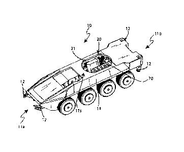
An armed vehicle (10) with improved structure comprising a hull (11), which, in use, is suited to house one or more men, a plurality of means for the movement on the ground, and an armed turret (30), which is positioned on top of an upper part of said hull (11); the armed vehicle (10) comprises an interface structural element (11s), which is cold-added; the interface structural element (11s) constitutes an interface element between the hull (11) and the armed turret (30).


French Abstract

Un véhicule blindé (10) à structure améliorée comprenant une coque (11), lequel, lorsquutilisé, est approprié pour loger un ou plusieurs hommes, une pluralité de moyens pour le mouvement au sol, et une tourelle armée (30), qui est positionnée sur le dessus dune partie supérieure de ladite coque (11); le véhicule blindé (10) comprend un élément structural dinterface (11s), qui est ajouté à froid; lélément structural dinterface (11s) constitue un élément dinterface entre la coque (11) et la tourelle armée (30).

Claims

Note: Claims are shown in the official language in which they were submitted.


1. Armed vehicle, comprising:
a hull configured to house at least one man when in use, said hull including a
front part,
a rear part and at least four corners, said hull extending from a front to
rear and side to side of
said vehicle, said hull defining a vehicle cockpit to facilitate driving the
vehicle;
a plurality of wheels for terrestrial maneuvering;
a turret armed with a howitzer and positioned upon an upper part of said hull;
an interface structural element; said interface structural element making an
interface
between said hull and said armed turret;
the hull including an opening positioned at the upper part of the hull, the
opening
connecting the hull to the turret; the hull comprising a plurality of
stabilizers arranged
proximate four of the corners of the hull;
an ammunition loading aperture positioned on said armed turret; said
ammunition
loading aperture being configurable between a first open configuration and a
second closed
configuration;
wherein in use in said first open configuration, said ammunition loading
aperture is
coupled to an ammunition loading chute and ammunition are translated by said
loading chute
into said turret; and
a storage and a pick-up device for a plurality of propelling charges of
ammunition for
said howitzer; said storage and said pick-up device being positioned inside
said hull and
corresponding to said opening positioned at the upper part of said hull.
2. The armed vehicle according to claim 1, further comprising dead holes,
wherein said dead holes comprise holes of substantially cylindrical shape,
arranged on a
plurality of parallel rows and housing said propelling charges in a direction
of maximum
extension substantially orthogonal with respect to the ground.
3. The armed vehicle according to claim 1 or 2, further comprising a
plurality of
external protection objects configured alternatively in a configuration
between an open
configuration and a closed configuration and wherein, in said open
configuration, said
external protection objects permit a separated access of the armed vehicle for
carrying out a
component maintenance, replacement or repairing operation.
4. The armed vehicle according to any one of claims 1 to 3, wherein the
stabilizers comprise extendible legs.
5. The armed vehicle according to any one of claims 1 to 4, wherein said
opening
comprises a rotation ring, installed upon said interface structural element.
9

Description

Note: Descriptions are shown in the official language in which they were submitted.


CA 02762441 2011-12-16
Armed vehicle with improved structure
The present invention is relative to an armed
vehicle, in particular it is relative to an armed
vehicle with improved structure.
It is known that in the military field armed
vehicles, both wheeled and tracked vehicles, are used,
which are typically provided with a hull for housing
the military personnel, on top of which there is at
least one turret, which is provided with an arm,
typically a howitzer or cannon, which can be associated
to one or more machine guns.
Typically, the turret can rotate with a round
angle, so as to be able to reach any firing direction,
irrespective of the alignment of the vehicle with
respect to a target to be hit.
Furthermore, the cannon or howitzer can be
adjusted in its elevation angle, i.e. the angle
existing between its carriage and the ground, so that
it is possible to define not only the firing direction,
but also the inclination of the latter, thus also
varying the distance of the point in which a projectile
will hit the target.
In particular, the cannon or howitzer of the
turret of the armed vehicle fires ammunitions that
typically comprise a first component, or projectile,
and a second component, or propelling charge.
When in use, the projectile is the first one to be
introduced into a breech of the carriage of the cannon
1

CA 02762441 2011-12-16
or howitzer; subsequently, the propelling charge is
introduced as well, following the projectile itself.
Traditional armed vehicles, in particular, present
limitations connected to those maintenance operations
during which the vehicle is partially disassembled, so
as to allow access to its internal parts, in order to
inspect them, service them or replace one or more
pieces.
In particular, in case it is necessary to check
parts that are close to or coinciding with the turret,
the latter has to be disassembled with a significant
waste of time.
Furthermore, traditional armed vehicles require a
lot of time to be supplied with ammunitions; typically,
the time deficit is particularly disadvantageous in
those theaters of war in which efficiency and rapidity
in ammunition rearmament, reloading and supply turn out
to be essential for accomplishing a mission.
When considering the ammunition supply of the
traditional type, it is necessary to keep in mind that
this type of ammunition supply requires a double
activity, since the armed vehicle has to be supplied
with both projectiles and propelling charges, which are
different from one another and are housed in magazines
or loaders which, in turn, are distinct and arranged in
different areas of the armed vehicle itself.
Therefore, the object of the present invention is
to describe an armed vehicle with improved structure,
which does not present the drawbacks described above.
2

CA 02762441 2011-12-16
According to the present invention, an armed
vehicle with improved structure is provided, which is
of the type claimed in the first claim.
The invention will now be described with reference
to the accompanying drawings, which illustrate a non-
limiting embodiment, wherein:
figure 1 illustrates a prospective view of
part of an armed vehicle with improved
structure according to the present invention;
- figure 2 illustrates a prospective view of
part of the vehicle of figure 1;
figure 3 illustrates a prospective view of
the vehicle of figure 1, which, in this case,
is side by side with an ammunition supply
vehicle;
figure 4 illustrates a plan view of figure 3;
- figure 5 illustrates a detail of figure 3;
and
figure 6 illustrates a detail of figure 1.
With reference to figure 1, number 10 indicates an
armed vehicle with improved structure as a whole.
Armed vehicle 10 comprises a hull 11, which is
suited to house in its inside one or more men, who are
at least in charge of driving armed vehicle 10 itself;
the hull is moved by means of wheels, as shown in the
figure, or by means of tracks, which are arranged on
the left and on the right of the hull itself. Both the
tracks and the wheels constitute comparable means for
the movement on the ground.
3

CA 02762441 2011-12-16
Hull 11 presents a front part 11a and a rear part
llp, which is opposite to front part lla and in
correspondence to which a plurality of stabilization
means 12 are arranged, close to respective corners.
Stabilization means 12 comprise a plurality of
legs, which can be extended and arranged either in a
first rest configuration, in which they do not
interfere with the ground and are lifted and folded
with respect to the ground, or in a second use
position, in which, instead, they are extended and
pressed against the ground, so as to guarantee a
statically indeterminate stabilization of armed vehicle
10.
Hull 11 comprises a cold-added interface
structural element lls, which acts as interface with a
turret.
Hull 11 presents, furthermore, an upper part,
which is provided with a substantially circular hole
20, into which a rotatory turret 30 is inserted, which
comprises at least one cannon, howitzer, or machine
gun, if necessary a multiple one.
The turret, besides being rotatory, also allows an
adjustment of the elevation angle of the cannon or
howitzer, i.e. an adjustment of the angle existing
between the ground and the carriage of the cannon or
howitzer, so as to allow the latter to hit targets that
are placed at different distances, regardless of the
propelling charge.
4

CA 02762441 2011-12-16
The cannon or howitzer preferably fires, though in
a non-limiting manner, ammunitions of the conventional
type, which consist of a projectile and a propelling
charge, which, in use, is inserted into the breech of
the cannon or howitzer before the firing.
Hole 20 presents a rotation ring 21, which is
installed on interface structural element lls and is
suited to guarantee a better rotation of turret 30.
Armed vehicle 10 comprises, furthermore, a
plurality of external protection bodies 40, which are
respectively arranged on the left and right side of the
vehicle itself and can be configured either in a first
open position or in a second closed position.
In the first open position, external protection
bodies 40 allow an easy access to the armed vehicle
and, in particular, to its inside, thus reducing the
number of hours that are needed to carry out
traditional maintenance/replacement/repair operations
on elements comprised in armed vehicle 10.
In the second closed position, external protection
bodies 40 are configured in such a way that they not
only forbid access to essential components or
accessories of vehicle 10, but also offer a higher
protection to armed vehicle 10 itself.
Furthermore, armed vehicle 10 according to the
present invention is provided with an ammunition
loading opening 50, which is arranged on one of the two
sides of the armed vehicle itself and, in detail, is
arranged on one side of turret 30.
5

CA 02762441 2011-12-16
Said ammunition loading opening 50, which can be
closed, presents a size that is slightly larger than
the one of a projectile and, therefore, allows the
semi-automatic supply of a reserve or loader present
inside the armed vehicle.
As illustrated in figure 3, in figure 4 and,
finally, in figure 5, armed vehicle 10 is first of all
positioned side by side with an ammunition supply
vehicle; subsequently, ammunition loading opening 50 is
opened and coupled to a loading chute 60; then, the
projectiles are translated by means of said loading
chute 60 into turret 30.
At the end of the loading operation, ammunition
loading opening 50 is closed again, thus allowing armed
vehicle 10 to resume its activity.
Since the projectile magazine or loader of armed
vehicle 10 is arranged in turret 30, the loading
procedure becomes particularly fast and it does not
need any longer a complete manual management, thus
allowing the operator or the person in charge of the
piece to stand in a much safer position and to work in
a more efficient way in terms of time.
For example, the assembly consisting of ammunition
loading opening 50 and loading chute 60 allows the user
to complete the loading operation of twenty cannon
projectiles in approximately five minutes.
As shown in figure 1 and, more in detail, in
figure 6, armed vehicle 10 is also provided with a
magazine or loader 70 for propelling charges 80. Loader
6

CA 02762441 2011-12-16
70 is operated in an automated manner by a main
automated system, which is controlled by at least one
data processing unit, which is designed to take care of
the extraction of a propelling charge 80 from
respective loader 70 after the insertion of a
projectile of an ammunition into the breech on a cannon
or howitzer mounted on the turret.
Obviously, loader 70 can be operated not only
through an automatic loading procedure, but also
through a manual redundancy command, which generates a
secondary system for the manual emergency loading of
ammunitions, which, therefore, is able to cause armed
vehicle 10 to work even in case of failure of the main
automated system.
In detail, loader 70 is mounted inside hull 20 in
correspondence to substantially circular hole 20, so
that above-mentioned propelling charges 80, which are
preferably arranged in a vertical position with respect
to the ground and are housed in a plurality of parallel
rows of dead holes with a substantially circular shape,
can be picked up by automatic propelling charge pick-up
means, which are suited, through a command of the data
processing unit, to pick up a propelling charge 80 from
the magazine or loader 70 and bring it to the turret,
so as to insert it at the end of a projectile, which
has been previously inserted into the breech of the
cannon or howitzer.
The advantages of the armed vehicle with improved
structure according to the present invention are known
7

CA 02762441 2011-12-16
in the light of the previous description. In
particular, armed vehicle 10 according to the present
invention allows propelling charges to be loaded in a
substantially automatic manner, thus remarkably
reducing the activity of the loading personnel; as a
consequence, loading operations are faster and less
subject to possible mistakes and, in this way, the
inactivity time of the vehicle, which is particularly
dangerous and inefficient in the theaters of war, is
reduced.
Furthermore, the armed vehicle according to the
present invention, thanks to the cold-added interface,
allows an easier coupling with turret 30.
Cold-added interface structural element 11s can be
used on different types of vehicles with standard
changes that have to be carried out to adjust it to the
specific case.
The possibility to partially open the armed
vehicle in case of maintenance or replacement
operations, once again, plays an advantage role in
terms of time needed to resume the full activity of the
armed vehicle, though without a reduction of the
intrinsic safety of the personnel inside the hull.
The device described above can be subject to
variations, additions and changes that are obvious to a
skilled person, without in this way going beyond the
scope of protection provided by the accompanying
claims.
8

Representative Drawing
A single figure which represents the drawing illustrating the invention.
Administrative Status

2024-08-01:As part of the Next Generation Patents (NGP) transition, the Canadian Patents Database (CPD) now contains a more detailed Event History, which replicates the Event Log of our new back-office solution.

Please note that "Inactive:" events refers to events no longer in use in our new back-office solution.

For a clearer understanding of the status of the application/patent presented on this page, the site Disclaimer , as well as the definitions for Patent , Event History , Maintenance Fee  and Payment History  should be consulted.

Event History

Description Date
Common Representative Appointed 2019-10-30
Grant by Issuance 2019-01-08
Inactive: Cover page published 2019-01-07
Inactive: Final fee received 2018-11-08
Pre-grant 2018-11-08
Notice of Allowance is Issued 2018-05-25
Letter Sent 2018-05-25
Notice of Allowance is Issued 2018-05-25
Inactive: Q2 passed 2018-05-16
Inactive: Approved for allowance (AFA) 2018-05-16
Amendment Received - Voluntary Amendment 2018-04-26
Change of Address or Method of Correspondence Request Received 2018-01-12
Inactive: S.30(2) Rules - Examiner requisition 2017-11-01
Inactive: Report - No QC 2017-10-29
Letter Sent 2016-12-02
Request for Examination Requirements Determined Compliant 2016-11-28
Request for Examination Received 2016-11-28
Amendment Received - Voluntary Amendment 2016-11-28
All Requirements for Examination Determined Compliant 2016-11-28
Inactive: Cover page published 2012-06-17
Application Published (Open to Public Inspection) 2012-06-17
Inactive: IPC assigned 2012-05-09
Inactive: IPC removed 2012-05-09
Inactive: IPC assigned 2012-05-09
Inactive: First IPC assigned 2012-05-09
Letter Sent 2012-05-01
Inactive: Single transfer 2012-04-05
Inactive: Filing certificate - No RFE (English) 2012-01-11
Application Received - Regular National 2012-01-11

Abandonment History

There is no abandonment history.

Maintenance Fee

The last payment was received on 2018-11-26

Note : If the full payment has not been received on or before the date indicated, a further fee may be required which may be one of the following

  • the reinstatement fee;
  • the late payment fee; or
  • additional fee to reverse deemed expiry.

Patent fees are adjusted on the 1st of January every year. The amounts above are the current amounts if received by December 31 of the current year.
Please refer to the CIPO Patent Fees web page to see all current fee amounts.

Owners on Record

Note: Records showing the ownership history in alphabetical order.

Current Owners on Record
OTO MELARA SPA
Past Owners on Record
ANDREA CHIAPPINI
MANUEL D'EUSEBIO
Past Owners that do not appear in the "Owners on Record" listing will appear in other documentation within the application.
Documents

To view selected files, please enter reCAPTCHA code :


To view images, click a link in the Document Description column. To download the documents, select one or more checkboxes in the first column and then click the "Download Selected in PDF format (Zip Archive)" or the "Download Selected as Single PDF" button.

List of published and non-published patent-specific documents on the CPD .

If you have any difficulty accessing content, you can call the Client Service Centre at 1-866-997-1936 or send them an e-mail at CIPO Client Service Centre.


Document
Description 
Date
(yyyy-mm-dd) 
Number of pages   Size of Image (KB) 
Description 2011-12-15 8 285
Abstract 2011-12-15 1 12
Drawings 2011-12-15 4 67
Claims 2011-12-15 3 80
Representative drawing 2012-05-15 1 14
Claims 2018-04-25 1 56
Representative drawing 2018-12-06 1 11
Filing Certificate (English) 2012-01-10 1 157
Courtesy - Certificate of registration (related document(s)) 2012-04-30 1 104
Reminder of maintenance fee due 2013-08-18 1 112
Reminder - Request for Examination 2016-08-16 1 117
Acknowledgement of Request for Examination 2016-12-01 1 174
Commissioner's Notice - Application Found Allowable 2018-05-24 1 162
Final fee 2018-11-07 1 45
Amendment / response to report 2016-11-27 2 79
Examiner Requisition 2017-10-31 4 293
Amendment / response to report 2018-04-25 5 189