Note: Descriptions are shown in the official language in which they were submitted.
CA 02762492 2014-03-03
SYSTEM, METHOD AND MONUM ENT
FOR LAND SURVEYING
BACKGROUND
i. Field ofthe Invention
[00021 This invention is rclatf.-.,d to systems, methods and structures usable
in
surveying or geographic information sciences.
2. Related Art.
100031 Surveyors have been using monuments to at least semi-permanently mark
geographic; positions for many years. Traditional survey monuments have been
made of granite,
concrete, wood andlor metal. Traditional survey monuments may include a large
permanent
magnet. The large permanent magnet allows a surveyor to locate the monument
using a
magnetic locator, such as those available from Solionstedt Instrument Company
of
Keameysville, WV.
SUMIVIARY OF THE DISCLOSED EMBODIMENTS
[0004] While traditional survey monuments are useful for marking a physical
location, they typically are not useftil for storingor providing any further
information. For
example, while the survey monument may be adorned with various text and/or
insignia that
can identify the monument and/or the surveyor who placed the monument, this
information
t nay not be available without removing the monument from the ground and/or
displacing the
soil around the monument. Not only can this be difficult and time consuming,
it also presents
a possibility of the monument- being moved and/or loosened from its position
and/or
orientation.. Likewise, simple engraved information (e.g., text, insignia,
etc), ean be forged
with simple engraving tools arid thus may not be reliably accurate,
100051 Further, it can bc difficult to identify one survey .monument from
another, or
CVCT1 from other metallic and/or ferrous objects. For exarnple, metal
conduits, unexploded
ordinance, buried metal (e.g.. rebar) and other objects that are often buried
under ground, can
present difficulty when trying to locate a survey monument. If such objects
are buried near a
survey monument and exhibit a magnetic field, they may be confused for the
survey
CA 02762492 2011-11-17
WO 2010/135641
PCT/US2010/035768
rriouu-rurnt when attempting to locate the monument with a rnfignetic locator.
As such, a
surveyor, or any other individual attempting to locate the monument for the
puipose of
geographic reference, may be mislead to believe that the survey monument is
located in a
different place than it actually is.
[00061 Misidentifying a desired 1110r1 1,1 ent (e.g., erroneously locating the
wron
monument or erroneously identifying a non-monument, ferrous object as the
desired
monument), can result in various safety, legal and/or other problems. if, for
example, an
individual attempts to locate a monument as a point of reference for
determining safe andlor
unsafe digging locations, a misidentified monument may result in an unsafe
location being
deemed safe and vice-versa. Likewise, a misidentified monument may result in a
landowner
miscalculating a boundary line of a property.
[00071 Additionally, as outlined above, traditional survey 11101111111ents
generall-y
include simple engraved markings and/or insignia, if they include any markings
at all, These
traditional markings and/or insignia may not be useful for updating any
information
associated with the survey monument and/or may be limitcsi in the amount or
the type of
information that can be shown. For example, traditional survey monuments may
be =guyed
with a serial number and/or a name or insignia of the individual or
organization that placed
the survey monument. This information alone nia.:y have only limited usability
and 111 ay not
be readily accessible if the survey momunent is buried below ground.
[00081 In various exemplary embodiments, a survey monument according to this
invention can be readily identified in relation to other survey monuments
and/or nearby
ferrous objects. In various exemplary embodiments, the survey monument can be
readily
identified 'without requiring a line of sight between the user and the survey
monument. In
various exemplary embodiments, the survey monument can be uniquely identified.
[00091 In various exemplary- embodiments, the survey monument is usable to at
least help store information about the survey monument and/or a location
around the survey
monument. In various ones of these exemplary embodiments, the infoimation
includes an
identification number that correlates 10 on.e Or rnore data entries in one or
more databases.
[00101 in various ex.emplary embodiments, the survey monument has a main body
that is primarily metal. In various ones of these exemplary embodiments, at
least a portion of
the main body is permeable to RF signals -within a desired range of
wavelengths.
[00111 In various exemplary embodiments of a survey system according to this
invention, the survey system includes a survey monument, an electronic reader
and a server.
2
CA 02762492 2011-11-17
WO 2010/135641
PCT/US2010/035768
In various exemplary embodiments, the server includes a database that stores
information
associated with one or more survey monuments.
[00121Jn variou.s exemplary embodiments of a survey system according to this
invention, the survey system includes one or more survey monuments, each
having one or
more electronic tags, a reader usable to read the one or more electronic tags
of the one or
more survey monuments and a server that includes a database usable to store
information
associated with at least one of the. on.e or inore survey monunients. In
various exemplary
embodiments, a user uses the reader to identify a survey monument to determine
if it is a
desired survey monum.erit J.n vari.ous exemplary embodiments, the reader may-
then send
identifying information of the identified survey monurnent to the server. In
return, the server
may send at least some of the information associated with the identified
survey monument to
the reader to display to the user.
100131 In various exemplary embodiments, the reader may interact with the
electronic tag and/or tììe server with a two-way comtnunication stream. For
example, the
reader may send information (e.g., data queries) and receive information back
from the
electronic tag or server (e.g., alphanumeric data responses). Additionally,
the reader may
include a transceiver for interacting with the electronic tag and a separate
processor for
processing the data received from the electronic tag andlor server. The
tra.n.sceiver and the
processor may be connected via suitable known or late,r-developed wired or
wireless
COMMUlli cation bus or protocol..
[00141 These and other features and advantages of various exemplary
embodiments
of systems and inethod.s according to this invention are described in, or are
apparent from, the
follov,iing detailed descriptions of variou.s exemplary embodiments of various
devices,
structures and/or methods according to this invontior,
BRIEF DESCRIPTION OF DRAWINGS
100151 Various exemplary embodim.ents of the systems and methods according to
this invention will be described in detail, with reference to the following
figures, wherein:
[00161 Fig. 1 is a series of perspective views of survey monuments according
to
exemplary embodiments;
10017j Fh.v.. 2 is a side, plan view of an exemplary monument fitted with an
electronic tag a.ceording to an exemplary embodiment;
3
CA 02762492 2011-11-17
WO 2010/135641
PCT/US2010/035768
[001.81 Fig. 3 is a side cross-sectional view of the monument shown in Fig, 2
with
the collar 210 positioned to expose. an electronic tag;
[001.9] Fig. 4 is a top plan view of the monument shown in Fig. 3 with the cap
removed;
[00201 Fig. 5 is a top plan view of an exemplary inoriument fitted with an
electronic
tag according to a second exemplary embodiment;
100211 Fig. 6 is a perspective partially exploded view of the monument shown
in
Fig. 5;
[0022] Fig. 7 is an assembled side plan view of the monum efl L shown in Figs.
5 and
6;
[0023] Fig. 8 is a perspective view of a monument with an upgrade sleeve
according to an exemplary embodiment;
10024. Fig. 9 is a perspective view of an upgrade kit according to an
exemplary
ern h o diluent;
[0925j Fig. 10 is a schematic block dia.gam of a system, -which includes an
exemplary monument, according to an exemplary embodiment,
[00261 Fig. 11 is a perspective view of another exemplary embodiment of a
monument fitted with an electronic tag according to any suitable embodiment
100271 Figs. 12-14 are a series of top cross-sectional views of monuments,
such as
the exemplary embodiment shown in Fig. 11;
[00281 Fig. 15 is a side cross-sectional view of an exemplary embodinient of a
monument fitted with electronic tags according to an exemplary entbodiment;
[00291 Fig. 16 is a side cross-sectional view of an exemplary embodiment of a
monument fitted with an electronic tag according to an exemplary embodiment;
[00301 Fig. 17 is a side cross-sectional view of the monument shown in Fig. 16
fitted with electronic tags according to another exemplary embodiment;
100311 Fig. 18 is a top plan view of the monument shown in Fig, 17 with the
cap
removed;
[00321 Fig. 19 is a side cross-sectional view of an exemplary embodiment of a
monument fitted with an electronic tag according to an exemplary embodiment;
and
100331 Fig. 20 is a sicdc cross-sectional view of an exemplary embodiment of a
monument including an electronic tag according to an exemplary embodiment,
4
CA 02762492 2011-11-17
WO 2010/135641
PCT/US2010/035768
DET.AILED DESCRIPTION- OF -EXEMPLARY EMBODIMENTS
100341 The following description relates to monuments -usable as geographic
markers (e.g,, to mark the location of an asset), Generally, the monuments are
provided at a
substantially fixed location and can be used, for example, as reference points
for dctenninir3g
other locutions. It should be appreciated that, although some of the below-
outlined
embodiments are directed toward survey MOritillients and particular uses of
survey
monuments, thr disclosed invention is usable with my object that has at least
a substantially
fixed, known location. For example, in various exemplary embodiments, instead
of or in
addition to using survey monuments, the disclosed invention may function as a
monument to
identify a bridge, a building, a portion of a rail road or a signpost. It
should also be
appreciated that the fixed location of the monument may be relative to a
moving Object (e.g.,
a monument may be provided for determining the settling of a structure or
land). Likewise,
the disclosed monuments may be utilized to identify the locations,
specifications or other data
relating to buried transformers, cables, conduits and the :like.
[00351 As outlined above, traditional survey monuments can be difficult to
locate
and/or difficult to identify. Traditional survey monuments are typically
identified using a
magnetic locator. The magnetic locator emits an audible signal related to the
strength of a
magnetic field in the area of the locator. A surveyor can thus identify a
magnetic object
below the ground based on the signal entitled by the locator. However, survey
monuments
may not be the only buried objects in the area that exhibit a magnetic field.
Generally, there
is no Simple way of identifying whether a specific object is a survey
monument, as opposed
to, for example, a buried cable, a buried conduit, a buried unexploded
ordinance, or oilier
buried ferrous objects.
[00361 in various exemplary embodiments of a. monument according to this
invention., the monument includes an electronic marker (e.g., an REID tag),
which may be
utilized to help identify the monument. Such identification may be related to
identifying the
monument as a survey monument (as opposed to, for example, some other buried
ferrous
object) or identifying a specific monument (as opposed to any other monument).
[0037] In various exemplary embodiments, the electronic tag or marker is an
REID
tag and includes an REID transceiver and an antenna. M various exemplary
embodiments,
the RFID tag is a passive REID tag and does not require a separate power
source. In various
exemplary embodiments, the RFD tag is an. active RFID tag and includes its own
power
source (e.g., a battery, a photovoltaic cell., etc.). Such active RFID tags
may be particularly
CA 02762492 2011-11-17
WO 2010/135641
PCT/US2010/035768
useful for penetrating metal Or other RF-resistant materials provided on or
around the REID
tag.
[00381 The RED tag may respond to a radio frequency (RF) signal (e.g., a
series of
radio frequency pulses) transmitted from an RFfD reader. In response to the RF
signal, the
R.FID tag may transmit an RE signal hack to the reader. The R.F signal
transmitted by the
RF[[) tag may include any information stored on the REID tag. For example, the
RiF signal
may include an identification number that identifies the specific RFD tag, and
thus the
specific monument or other asset associated with. that RFID tag (e.g., a
permanently locked
alphanumeric number of a standard length), a geographic position attic RFD tag
and/or the
survey marker (e.g., GP S coordinates:, latitude and longitude readings,
Puhlic Land Survey
System (I'llaSS) coordinates, etc.), information about the date the monument
was placed
and/or updated, who placed the monument; who last updated the information
associated with
the monument and/or any other desired infomiation. Additionally, the RFID tag
may be able
to receive inform.ation from the :RED reader and encode that information into
a. memory of
the RFID tag.
[00391 Fig. 1 shows a series of perspective views of exemplary survey- 111011
um ents =
As shown in Fig. 1, the survey monuments may include, for example, a drivable
monument
102 (e.g., a survey monument that has a housing of a form (e.g., shape) that
is particularly
useful .for driving into the ground using any known or later-developed methods
and tools
-usable by a person having ordinary skill in the art); an anchored monument
104, which may
have a housing that includes one or more flared flanges 105; a breakaway
monument 106,
which may have a housing that includes a portion 107 that may break away from
the rest of
the housing if the monument is forcibly removed from the ground or otherwise
disturbed
from its location; a low profile monument 108; a disc-shaped monum cat;
arid/or any other
known or later-developed types and/or shapes of monuments usable tar
surveying; asset
management and/or geographic sciences. Additionally, objects that are not
traditionally
identified as monuments may be utilized. In general; the monument may be any
object that
maintains a substantially fixed geographic location (relative to the earth or
any other desired
reference point) and is subsequently desirabl:,,/ located and/or identified.
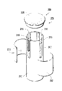
[00401 Figs. 2-4 show a series of views of a portion of a monument 200 (e.g.;
a
drivable monument generally similar to survey -monuments 102, 104 and 106
shown in Fig.
1) fitted with an electronic tag 300 according to an exemplary embodiment. As
shown in Fig.
2, the monument 200 comprises a housing 205 having a generally tube-shaped
body or body
6
CA 02762492 2011-11-17
WO 2010/135641
PCT/US2010/035768
=
portion 210 and a cap 220. in various exemplary embodiments, the tube-shaped
portion 21 0
is a hollow, metal cylinder or pole with an internal void 212 (as shown in
Fig. 4). The
monument 200 also includes a cover 230. As shown in Fig, 4, in various
exemplary
embodiments, one or more slots 216 are provided in dm tube-shaped portion 210
of the
monument 200. lt should be. appreciated that the slots 216 may be created
during the
formation of the tube-shaped portion 210, cut out of thc tube-shaped portion
210 at some later
time, and/or provided in any other known or later-developed manner.
[00411 As shown in Fig. 3, the monument .200 includes a magnet 222, which may
be supported, incorporated into or otherwise associated with the cap 220. As
outlined above,
the magnet 222 is usable to help locate the monument 200 using any known or
later-
developed equipment and/or method for locating magnetic objects (e.g., buried
survey
monuments). The electronic tag 300 (e.g. ar RF D tag) is provided in the
internal void 212
of the tube-shaped portion 210. in an exemplary embodiment, the electronic tag
300 includes
a metal hacking plate or bracket 310. As shown in Figs. 3 and 4, one or rnore
rivets, bolts,
screws or the like may be provided that extend between two of the one or more
slots 216 and
through the electronic, tag 300 and/or bracket 310 to secure the electronic
tag 300 and/or
bracket to the housing 205 (e.g., to the tube-shaped portion 210) of the
monument 200. It
should be appreciated that any known or later-developed fastener, adhesive, or
the like may
be used to secure the electronic, tag 300 to the 'bracket 310 and /or the
housing 205 of the
111.0111itil mt. 200. For the purposes of this application, all such
fasteners, adhesives or the like
-will be considered part of the housing of the monuments.
100411 Fig. 5 shows a top view (with the cap 220 removed) of a second
exemplary
methixl for securing the electronic ta.g 300 to the housing 205 of the
monument 200 (e.g., to
the tube-shaped portion 210). As shown in Fig. 5, the electronic tag 300 may
be glued or
otherwise secured to one or rnore of the. slots 216 of the tube-shaped portion
210 of the
monument 200. It should be appreciated that the electronic tag 300 may be any
suitable size
or shape. Likewise, two or more electronic tags may be provided in the one or
more slots
216. it should also be appreciated that the slots 216 may act as wave guides
to promote the
penetration of signals (e.g., RF signals to and/or from the electronic tag
300).
[00431 ha various exemplary embodiments, the electronic tag 300 may be
position.ed
such that it is flush to an external surface of the tube-shaped portion 210
andlor other portions
of the housin.g 205 of the monument 200. It should be appreciated that it may
be desirable
for the electronic tag 300 to be flush with the external surface of the tube-
shaped portion 2 1 0
7
CA 02762492 2011-11-17
WO 2010/135641
PCT/US2010/035768
to permit the electronic tag 300, or an antenna of the electronic tag 300, to
be optimally
exposed to external RF or other electronic signals.
[00414] Fig. 6 shows a partially exploded, perspective view of a portion of
the
monument shown in Fig. 5. Fig, 7 shows a side plan view of a portion of the
monument
shown in Fig 5 (after a.sserobly), As shown in :Fig. 6, a cap 220 (e.g., a
conventional brass
cap similar to those used on traditional survey monuments) may be placed over
the end of the
tube-shaped. portion. 210 of the monuillent 200 and may cover at least a
portion of the one or
more slots 216. It should be appreciated that, in various exemplary
embodiments, at least a
portion of the electronic tags 300 will be visible below the bottom of the cap
220, such that at
least an antenna of the electronic tag 300 is exposed through the slot 216.
00451 As shown in Figs. 6 and. 7, in various exemplary embodiments, a cover
230
is provided over the outer surface of a portion. of the housing 205 (e.g.,
around the tube
-
shaped portion 210) of the monument 200. .As shown in Fig. 7, the cover 230
may separate
the one or more slots 216 from the external environment In variou.s exemplary
embodiments, the cover 230 helps provide a hermetic seal that protects the
electronic tag 300
fro-na the conditions of the external environment (e.g., moisture). It should
be appreciated that
the cover 230 is generally made of an -RF permeable material (e.g., a material
that allows R.17
waves of' a desired wavelength to pass through the material). In this manner,
the electronic
tag 300 may be sealed from the external environment, yet accessible for
communication with
electronic equipment using RI' waves of a desired wavelength.
100461 It should be appreciated that the cover 230 may be a single piece
(e.g., a
sleeve around the tube shaped portion 210) or may be comprised of one or more
portions
(e.g., the portions 230 and 232 shown in Figs. 6 and 7) that interconnect to
separate the one or
more slots 216 from the external environment. Likewise, it should be
appreciated that
multiple covers may be provided to separate any one or more of the one OT
1110re slots 216
from the external environment.
[00471 Fig. 8 shows an exemplary einhodiment of a monument 200 (e.g., an
anchored monument similar to the anchored survey monument 1.04 shown in Fig.
I) with an
upgrade sleeve 400. The upgrade sieevc. 400 is usable to atta.ch an electronic
tag (not Shown)
to a housing 205 of a pre--existing monument 200. It should be appreciated
that the
monument 2C,10 may be any of the herein-outlined or other known or later-
developed
exemplary embodiments of monuments. It should also be appreciated that the
electronic tag
may be incorporated into a portion of the upgrade sleeve 400 andlor secured
between the
8
CA 02762492 2011-11-17
WO 2010/135641
PCT/US2010/035768
upgrade sleeve 400 and the monument .200. For example, the electronic tag may
be provided
on the outer surface of the housing 205 of the monument 200 and the upgrade
sleeve 400
provided over the electronic tag. As such, the upgrade sleeve 400 helps to
attach. the
electronic tag to the housing 205 of the monument 200 (e.g., to a tube-shaped
portion 210 of
the monument 200) and/or to protect the electronic tag without requiring
significant structural
changes to the monument 200. ft should be appreciated that the upgrade sleeve
400 may be
shaped or adapted to conform to the outer surface of any portion of the
housing 205 of the
monument 200.
[0048j Fig. 9 shows an exemplary embodiment of the upgrade sleeve 400. The
exemplary upgrade sleeve 400 includes one or more portions 410 and one or more
ties 420.
In the exemplary embodiment shown in Fig. 9, the portions 410 can be combined
to provide a
cylindrical collar that fits around the housing 205 (e.g., the tube-shaped
portion 210 or an
outer surface) of the monument 200, as shown in Fig. 8. The one or rnore ties
4:20 are usable
to secure the portions 410 together around the monument 200. It should be
appreciated that
the ties 420 may be replaced with any appropriate known or later-developed
material,
apparatus or method that is usable to connect the portions 410 of the upgrade
sleeve 400
together (e.2., in a ring around the monument 200). For example, the ties 42.0
may be
replaced with screws, rtUtS, bolts, glue, epoxy, sonic welding, a tongue and
groove style
connection and/or any other material, apparatus or method usable to connect
the portions 410
together. Likewise, the upgrade sleeve 400 may be a single cylindrical-shaped
sleeve that fits
around, and secures to, the housing 205 of the monument 2.00. Once so secured,
for the
purposes of this application, the upgrade sleeve 400 becomes a portion of the
housing 205. It
should be appreciated that, in various exemplary embodiments, the upgrade
sleeve 400 may
not encircle or surround the monument 200. In various exemplary embodiments,
the upgrade
sleeve 400 May be attached to one side of the monument 200 and may include a U-
bolt,
clamp or the like that secures and incorporates the upgrade sleeve 400 as part
cif the housing
205 of the monument 200.
[00491 Fig. 10 shows a block diagram of a location system 800. As shown in
Fig.
10, the location system 800 includes at -least one monument 810, which may be
any of thc
herein-disclosed monuments and/or any other known or later developed suitable
monuments.
The monument 810 is placed in. a d.esired location which is to be later
located arid/or
identified (e.g., buried at the location of an asset, attached to an asset,
buried at a desired
reference point, etc.). In general, the monument 810 is usable to mark a
location and./or an
9
CA 02762492 2011-11-17
WO 2010/135641
PCT/US2010/035768
object (e.g., by being buried at a desired location, attached to a desired
object, or embedded
in a desired structure), The monument 810 includes a magnet 812 and an
electronic tag 814.
in various exemplary embodiments at least one of the magnet 812 and the
electronic tag 814
is attached to a housing of the monument 810, in various exemplary embodiments
at least
one of the magnet 812 and the electronic tag 814 is contained within the
interior of the
housing of-the monument 810.
[0050] A magnetic: locator 820 is usable to perceive (e.g., detect or measure)
a
magnetic field 822 emitted by the magnet 812, As outlined above, by perceiving
the
magnetic field 822 of the magnet 812, the magnetic locator 820 limy be used to
locate the
monument 810 (=.µ,ven if 14)(z; rmìnu.rilent 810 is not visible (e.g., as when
the Mailitillerit 810 is
buried below ground). In various exemplary embodiments, the magnetic locator
820 can he
used to quickly determine a location where the emitted magnetic field 822 is
at its maximum
arid which relates to a location of the monument 810 (e.g., the magnetic field
822 will
generally be larger ,when the magnetic locator 820 is closer to the
ITI011UtriCrit 810 and thus
-will reach a maximum when placed directly above a buried monument 810).
I00511 An electronic transceiver 830 is usable to send and receive electronic
signals
832 to and from the electronic tag 814. in various exemplary embodiments, the
electronic tag
814 is an RFD tag and the electronic transceiver is an R.FID reader. In such
exemplary
embodiments, the MID reader sends a signal (e.g., a series of pulses) to the
R.FID tag and thc
R.FID tag responds with a signal, lt should be appreciated that the RFID tag
may be a passive
RED tag (e.g., powered by the signal sent fi-orn the RFID reader) or an active
RFID tag (e.g.,
an REID tag that includ.es its own power supply).
[00521 The electronic! transceiver 830 is in communication with a handheld
computer 840. In the embodiment shown in Fig. 10, the electronic transceiver
is connected to
the handheld computer 840 via. a wired conrieetion 834. However, it should be
appreciated
that in various other exemplary embodiments the electronic transceiver 830 may
be
wirelessly connected to the handheld computer 840, while in still other
exemplary
embodiments, the electronic transceiver 830 and the handheld computer 840 are
the same
device or el em ents of the same device (e.g., the handheld computer 840 may
include the
electronic transceiver 830).
[00.531 The handheld computer 840 is in communication with a server 850. In
the
embodiment shown in Fig. 10, the handheld computer utilizes wireless link 842
to
communicate with the server 842. It should be appreciated that the wireless
link 842 may be
CA 02762492 2011-11-17
WO 2010/135641
PCT/US2010/035768
any known or later-developed wireless communication link (e.g., a cellular
data network, a
Bluetooth connection, etc.). Likewise, the wireless link 842 may be replaced
with a wired
connection such as, for example, an RS-232 serial connection, an 12i3. serial
connection,
and/or any other known or later developed connection suitable for providing
communication
between the handheld computer 840 and. the server 8.50. Additionally, it
should be
appreciated that the server 850 maybe combined with the handheld computer 840
in a single
device. That is, rather than a traditional external server, the handheld
computer 840 may
utilize internal memory, processing, data storage and the like to perform the
functions of a
server 850.
100541 ln the exemplary embodiment shown in Fig. 10, the server 850 includes a
database 852. The database 852 may be usable to store information via any
known or later-
developed architecture. In various exemplary embodiments, the database 852
will store
information that relates to one or more monuments 810 that can be located with
the magnetic
locator 820 and communicated with via the electronic transceiver 830 in
various exemplary
embodiments, a unique identification number is stored on the electronic tag
814 of one or
more monument 810 in such exemplary embodiments, the unique identification
number
may be usable to query relevant information stored in the database 852 of the
server 850. For
example, in various exemplary embodiments, the database 852 may contain
information
about the service history of several monuments 810 including a unique
identification nuinber
for each monument 810. In such exemplary embodiments, when the electronic
transceiver
830 receives the unique identification number from the electronic tag 814 of a
particular
monument 810, the handheld computer 840 ma.y be used to query the service
history of that
particular monurnent 810 by sending the unique identification number of the
particular
monument 810 to the server 850.
[00551 In an. exemplary method of using the location system 800, a user probes
a
desired area (e.g., an area with one or more buried momunents 810) with the
magnetic locator
820 until the magnetic locator 820 registers a maximum of a. m.a.grietie field
(e.g., when the
:magnetic locator is directly above a buried monument 810). The user then -
utilizes the
electronic transceiver 830 to confirm the identity and send a sipal to the
electronic tag 814
of the located monument 8141. The electronic tag 814 responds with a signal
that relates to
desired information about the located monument 814 (e.g., a -unique
identification number).
In turn, the handheld computer 840 communicates with the server 850 to
retrieve relevant
infOrmation about the located monument 814.
11
CA 02762492 2011-11-17
WO 2010/135641
PCT/US2010/035768
[0056] It should be appreciated that any desired infOrmation may be stored on
the
server 850 and/or in the database 852. For example, the server 850 andior the
database 852
ma.y store information related to a service history (e.g., install date,
maintenance records,
projected reinevallreplacement date, etc.) of the monument 810 and/or an
object related to the
monument 810. Likewise, the server 850 an.dlor the database 852 may store
information
about the location of the monument 810 and/or an object associated with the
monument 810.
For example, in an exemplary embodiment, the monument 810 may be attached to,
or
otherwise associated with, a bend, junction, valve, or the like provided in a -
buried pipe,
conduit, or the like. In such exemplary embodiments, a service technician may
be able to
locate the bend, junction, valve or the like by utilizing the magnetic locator
820 to locate the
MOMMIent 810 as outlined above. The service technician may then verify that
the correct
bend, junction, valve, or the like has been found by sending and receiving a
signal to and
from the electronic tag 814 using the electronic transceiver 830 in. order to
determine an
identification number of the located bend, junction, valve or the like. The
service technician
may then query the server 850 arid/or database 852 using the identification
number to
determine a service history of the bend, junction, valve or the like.
Likewise, the service
technician may send information related to the bend, junction, valve or the
like to be stored.
on the server 850 and/or database 852. For example, the service technician may
send the
date, time and results of an inspection of the bend, junction, valve or the
like to be stored in
the server 850 and or database 852 to be accessible by later users inspecting
the bend,
junction, valve, or the like.
10057-1 Fig. 11 shows another exemplary embodiment of the monument 200. In the
embodiment shown in Fig. 11, the housing 205 of the monument 200 includes one
or more
holes 216 (e.g., in the pole-shaped portion 210 of the body 205). In various
exemplary
embodiments, the holes 216 allow RF signals to penetrate the monument 200. in
this way, if
an elc...ctronie tag is placed in the internal void of the monument 200, the
RF signals rvili be
able to reach the antenna of the electronic tag.
[0058] It should be appreciated that the inonoment 200 inay include any number
of
slots or holes 216. Figs. 12-14 show an exemplary embodinic-..nt including
four holes 216. It
should he. appreciated that the shape and/or size of the slots or holes 216
may be chosen KWh
that the slots or holes 216 act as waveguides and direct RF signals of a
desired wavelength
into the interior void of the monument 200. .As such, if an electronic tag is
placed in the
interior void of the monument 200, the RI signals will be able to reach an
antenna of the
12
CA 02762492 2011-11-17
WO 2010/135641
PCT/US2010/035768
electronic tag. As shown in Fig. 11, a cap 220 may be provided over at least a
portion of the
tube-shaped pOrti 011 210 of the 11101111Malt. 200, it should be appreciated
that, in various
exemplary embodiments, the cap 220 may extend over at least a portion of one
or more of the
slots or holes 216. In various exemplary embodiments, at least a portion of
the cap 220 is RI?
permeable and allows R.F signals of a desired wavelength to pass through the
cap 220 and the
holes 216 and into the interior void of the monument 200.
[00591 Figs. 12-14 show a series of cross-section views of monuments, such as
the
exemplary embodiments shown in Figs. 2-7 andlor 11. An electronic tag 300 is
shown in the
internal void of the tube-shaped portioh 210 of the monument 200. It should be
appreciated
that the electronic tag 300 may be attached to the housing of the monument
(e.g., to the tube-
shaped portion 210) according to any of the above-outlined or other exemplary
embodiments.
As shown in Fi.g. 12, the shape of the slots or holes 216 may include
approximately parallel
walls, such that an internal width of a given slot or hole 216 is
approximately the same as an
external width of that slot or hole 216. Alternatively, as shown in Fig. 13,
the slots or holes
216 may include divergent walls, such that the externai width of a given slot
or hole 216 is
smaller than the internal width of that slot or hole 216. As shown in Fig. 17,
in yet another
alternative embodiment, the slots or holes 216 may include convergent walls,
such that the
external width of a given slot or hole 216 is larger than the internal width
of that slot or hole
216.
[00601 Fig. 15 shows a partial cross-section of an exemplary breakaway
MOTIUrriell t
500. As shown. in Fig 15, the breakaway monument 500 has a housing 505 that
includes a
seated body portion 510, a neck 520 and a head 530. In use, the breakaway
monument 500
may be buried in the ground such that the seated body portion 510 is securely
embedded in
the ground, if the breakaway monument 500 is disturbed (e.g., -pulled out of
the ground,
pushed horizontally, etc.), the breakaway monument 500 may break at its neck
portion 520
such. that the head 530 of the -breakaway monument 500 follows the disturbance
while the
seated body portion 510 remains in place. it should be appreciated that a tube-
shaped portion
(e.g., the above-outlined tube-shaped portion 210) may be provided between the
upwardly
opening -portion 540 of the neck 520 and the head 530 of the breakaway
monument (e.g., as
in the breakaway survey monument 106 shown in Fig. 1).
[00611 The seated body portion 510 of the housing 505 of the breakaway
monument
500 includes a base plate 512 and one or more wings 514. The base plate 512
and/or wings
514 may help secure the seated body portion 510 of the breakaway monument 500
within the
13
CA 02762492 2011-11-17
WO 2010/135641
PCT/US2010/035768
ground when the breakaway .moriument 500 is buried. An electronic tag 300 is
secured to the
base plate 514 of the housing 505 of the breakaway monument 500. In the event
that the
breakaway monument 500 is disturbed such that the breakaway monument 500
breaks
leaving only the seated body portion 510 behind; the electronic tag 300 may
continue to
provide the desired information relative to the breakaway monument 500 and/or
the
environment around the breakaway monument 500. A metal backing plate 320 is
provided
beneath the electronic tag 300. In various exemplary, embodiments, the backing
plate 320
helps improve reception and/or transmission of electronic signals by the
electronic tag 300.
In various exemplary embodiments, the hacking plate 320 reflects some of the
RE signals that
pass past the electronic tag 300 back toward the electronic tag 300.
Additionally, a magnet
516 is provided in the seated body portion. 510 of the housing 505 of the
breakaway
monument 500. The magnet 516 may help locate the seated body portion 510 of
the
breakaway monument 500 after the monument or the overlying soil has been
disturbed
according to the above-outlined process.
[00621 The head portion 530 of the housing 505 of the breakaway monument 500
includes a cap 534 that separates an internal void of the monument 500 from
the external
environment. The head 530 of the breakaway monument 500 may also include a
magnet 532
and/or an electronic tag 300.
100631 Figs. 16-19 show exemplary embodiments of low profile monuments. As
shoµvrt in Figs. 16 and 17, an exemplary low profile monument 600 has a
housing 605, that
includes a cap 610 and a base plate body 620. The low profile monument 600
also includes a
magnet 630 located within the housing 605 of the low profile monument 600. In
various
ex.emplary embodiments the base plate body 620 may include one or more holes
622. The
holes 62.2 May help secure the low profile monument 600 to buried ermduits,
cables, pipes or
any other known or later-developed object that may be. desirably located. In
the exemplary
embodiment shown in Fig, 16, thc base plate body 620 also includes one or more
projections
624 (e.g., a nail, spike, or the like). The one or more projection 624 may be
useful for
securing the low profile monument 600 to a desirabl.y located object. .As
shown in Fig. 16, an
electronic tag 300 and a metal backing plate 320 are attached to the cap 610
of the housing
605 of the low profile monument 600. As outlined above, the metal backing
plate 320 may
help improve the reception and or transmission of electronic signals to andlor
from the.
electronic tag 300. It should be appreciated that the electronic tag 300
andior the backing
plate 3'20 may be secured to the cap 610 in any suitable. known or later-
developed way. lu
CA 02762492 2011-11-17
WO 2010/135641
PCT/US2010/035768
various exemplary embodiments, the electronic tag 300 is secured to the
backing plate 320
(e.g., -using one or more rivets, epoxy, adhesive, or the like) and the
backing plate 320 and/or
the electronic tag 300 is secured to the cap 610 (e.g., with adhesive or the -
like).
[00641 As shown in Figs. 1.7 arid 18, one or more electronic tags 300 and/or a
metal
backing plate 320 may be secured to the base plate body 62.0 of the housing
605 of the low
profile monument 600 in addition to or instead of being secured to the cap
610. It should be
appreciated that the one or illOrC electronic tags 30C) may be attached to the
housing, 605 of
the lol,v profile monument 600 by securing the one or more tags 300 to a
backing plate 320
(e.g., 811 aluminum or stainless steel washer) and then securing the backing
plate 320 to the
base plate body 620. It should be appreciated that while the one or more
electronic tags 300
are shown in Figs. 16 and 17 on either side the magnet 630 (with the magnet
630 being
centrally located on the base plate 620), in various exemplary embodiments,
the magnet 630
may be offset to one side of the base plate 620 and backing plate 320, and the
one or more
electronic tags 300 ma.y be offset to th.e middle or an opposite side of the
backing plate 620.
The magnet pocket in the base plate body 620 and the ma pet opening in the
backing plate
320 ,,vould be likewise offset to whatever position is desired for the magnet
630.
[00651 Fig. 19 shows another exemplary em-hodiment of a low profile monument
700. As shown in Fig. 19, the low profile monument has a housing 705 that
includes a metal
backing plate 320 and a cap 710. The low profile monument 700 also includes a
magnet 720
and an electronic tag 300 secured to the housing 705 of the low profile
monument700. In the
embodiment shown in Fig. 19, the electronic tag 300 is secured to the metal
backing plate
320 and/or the cap 710 of the low profile monument 700 and is provided within
the housing
705 of the low profile monument 700, while the magnet 620 is secured to the
backing plate
320 and provided outside of the housing 705 of the low profile monument 700,
The low
profile monument 700 may be particularly usefid as a survey monument which can
be buried
in the concrete or asphalt of a highway or parking lot extending over a unique
geographical
point, such. as a section comer, where it can be quickly located by use of a
magnetic locator
and identified and updated without breaking up and excavating the collet-4.ft
or asphalt
overlay by sending an electronic signal to the electronic tag of the monument
and reading and
updating the inthrmation on the tag.
100661 Fig. 20 shows another exemplary embodiment of a monument 200
comprising an electronic tag 300 having an outer body portion 302. which
comprises a portion
of a housing 205 of the monument 200. As shown in Fig. 20, a reflector plate
320 is secured
CA 02762492 2011-11-17
WO 2010/135641
PCT/US2010/035768
to the lower surface of the housing 205. A cap 226 is attached to die housing
205 and a
magnet 224 is provided within the cap 226. in various exernplary embodiments,
the magnet
224 is also attached to the body portion 302 of the housing 305 of the
electronic tag 300,
[0067] In various exemplary embodiments, each of the above outlined electronic
tags (e.g., the electronic tag 300) inchides a memory that stores an
identification nuinher of
that electronic tag. In various exemplary embodiments, the identification
numbers of each
RFID tag are associated with information stored in a database. The database
may include
information about the tag and/or the geographical location around the tag. For
example, the
database may include information about land rights (e.g., boundaries of
ownership), global
positioning system coordinates of the monument, other known buried objects in
the area
(including other ferrous objects), information regarding previous inspections
of the area
and/or any other known or later-developed information.
[0068] in various exemplary embodiments, some or all of the inform.ation
stored on
the electronic tags is electronically locked (e.g., permanently or via one or
more security
protocols) to, for ex.ample, reduce or prevent counterfeiting and/or
tampering.
[0069] Additionally, the identification number of the electronic tag can be
used to
verify that an individual visited the site. For example, the reader used by a
surveyor may
keep records of recently read monuments to verify= that the surveyor in fact
actually visited
the location of the surveying m.oriuments. Likewise, individual's that are
required to patrol
various locations (e.g., border patrol, security guards, etc.) may carry a
portable or vehicle
-
mounted reader that locates and a.u.torna.tically interacts with asset
monuments in the vicinity
of the individual and. stores information obtained from those monuments. After
cornpleting
the required patrol route, the identification numbers or other information can
be used to
verify that the individual traveled through the required area.
[0070] In various exemplary embodiments, the reader is connected (e.g., via
wired
or wireless network, such. as, for exanwie, over a cellular network, a Wi-Fi
network, wireless
interact connection or the like) to a server that includes the database. In
various exemplary
embodiments, the reader can display information received from the. server and
related to an
electronic tag read by the reader,
[0071] In one exemplary embodiment of a method for interacting with a survey
monument that includes an electronic tag, a surveyor locates the general
location of a survey
monument using, for example, a land survey map, 'The surveyor may then quickly
locate and
identify the survey monument using a magnetic locator aimed in the general
location of the
16
CA 02762492 2011-11-17
WO 2010/135641
PCT/US2010/035768
survey monument. He may then confirm the identity of the monument by sending
au.
electronic signal to the MOIllatient using an 1?,..FID transceiver (RFID
reader). The RFID
reader may then display useful information to the surveyor, such as, for
example, the type of
survey monument, the location of the monument, as identified by a global
navigation satellite
system (e.g., GPS, (ialileo, etc.), the location and type of other known
objects (ferrous and/or
othenvise) in the area, such as objects that ma.y interfere with a magnetic
locator, land rights,
property boundary lines, easement boundaries and the like for the area and/or
any other
known or later-developed types of inforrnation desirably related to or
associated with the
location of the survey monument.
[00721 The surveyor rnay then take any appropriate action as dictated by the
information received from the server, rnay update information on the server in
response to
observed or otherwise known changes in the area associated with the surveying
monument
and/or may update information stored OT1 the electronic tag of the surveying
montunent.
[00731 in other exemplary methods for interacting with a located monument that
includes an electronic tag, such interaction may be related to, for exanipl c,
inspection, record
keeping andlor verification of site visits. For example, that interaction may
he related to
bridge inspections, tunnel inspections, rail inspections, darn monitorin.g,
telephone pedestal
monitoring, gas transmission monitoring, elevator maintenance, traffic light
maintenance,
highway sign record keeping, forestry record keeping, commodity record keeping
(e.g.,
crops, petroleum, natural gas, mineral exploration, etc.), ITVA.0 servicing,
parks and
recreation site visits and the like:.
100741 Likewise, any service, technology- or industry that can utilize
location-based
information may utilize variants of the above outlined surveying systems. in
various
exemplary embodiments, the information stored in the database may be related
to other city-
:planning, civil engineering and/or geographic management services. For
example, business
models may utilize location-based markers to identify local community needs
and services in
relation to population.
[00751 Further, in various exemplary embodiments, the above-outlined surveying
system is incorporated into arid/or includes other geographic information
systems (GIS)
and/or software. For example, the above-outlined surveying systern may be
incorporated into
or otherwise compatible with known or later-developed G-IS software such as
that available
from ESRI of Redlands, CA.
17
CA 02762492 2014-03-03
100761 A surveying system includes a monument with a permanent magnet and an
electronically accessible tag or memory, a magnetic. locator, an electronic
reader and a server.
The magnetic locator is usable to quickly locate the monument. The reader is
usable to
identify the monument by electronically interacting with the tag or memor_,v.
The reader is
also usable to receive information from the tag or memory. The reader is in
communication
with the servk.T. The server includes at least one database that stores
information related to
the monument. The reader is usable to send the information received from the
electronic tag
or memory of the monument to the server and in return receives information
related to the
monument frorn the server. The reader may also be usable TO add to, subtract
from and/or
alter the information stored. in tbe electronic tag or memory.
10077] A server includes at least one. database. The database include.;
information
related to a geographical location or fixed asset identified by at least one
monument. Upon
receiving information identifying one such monument; the server outputs at
least some of the
information related to that monument andlor the geographicai location or fixed
asset
identified by that monument.
100781 The scope of the claims.should not be limited by particular embodiments
= set forth herein, but should be construed in a manner consistent with the
specification as a whole.
18